Week 9 - Challenge 2 - Switch Bezel Design
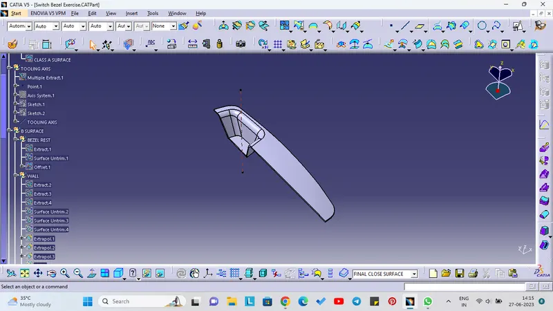
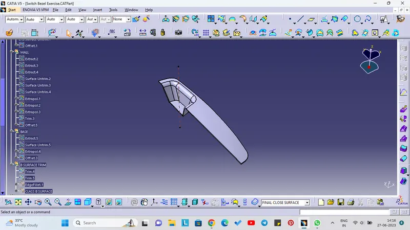
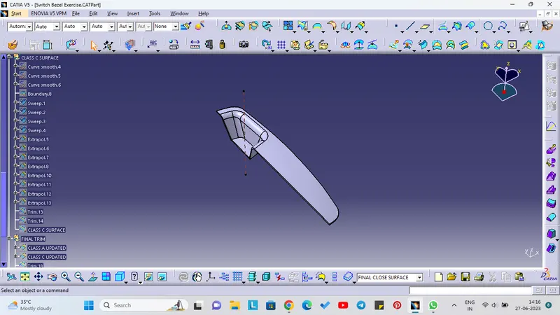
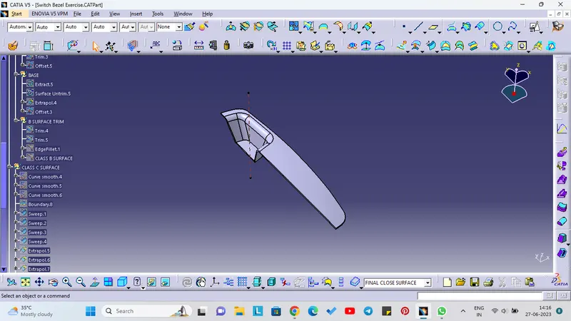
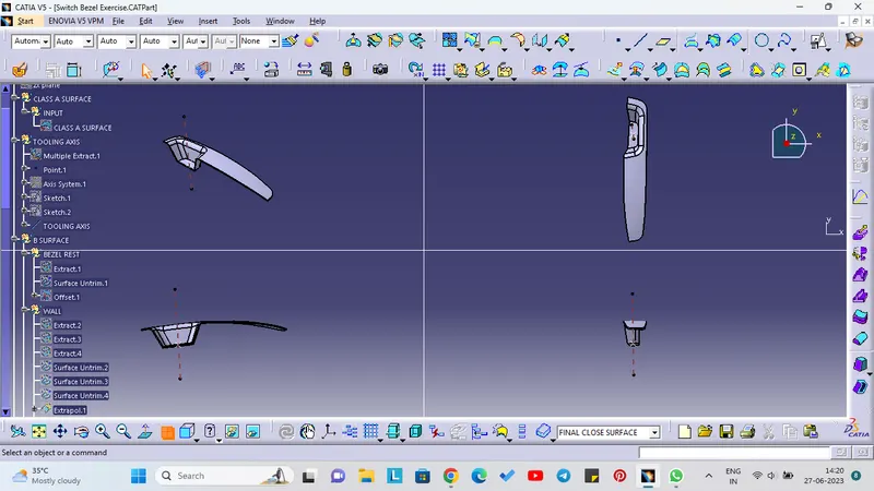
Tooling Axis Creation
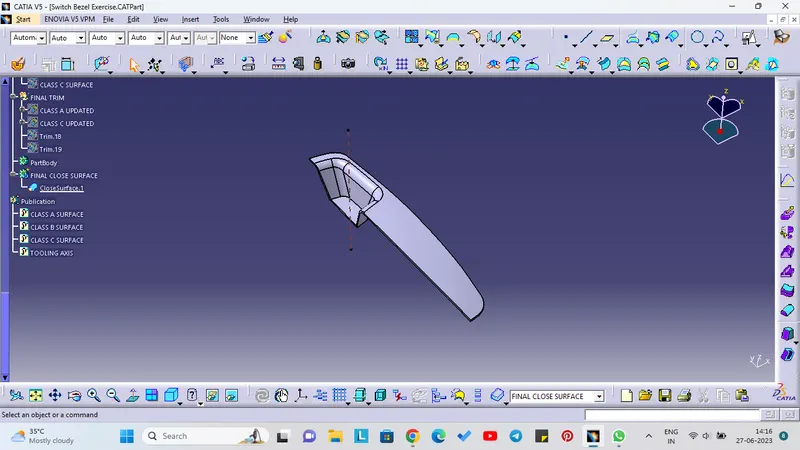
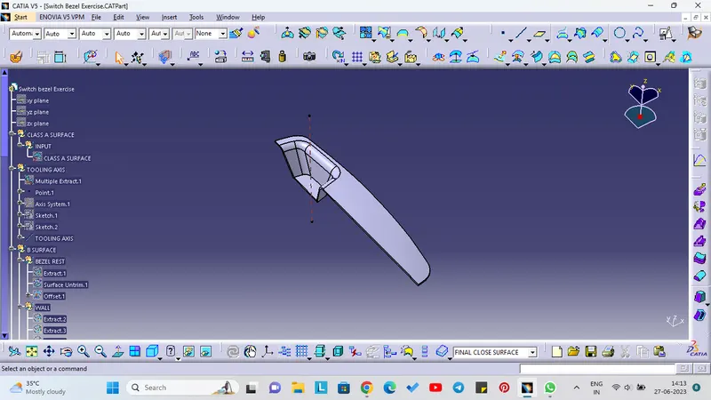
- Take the class A surface
- Extract the bottom face and create the Origin Point
- Choose the Line command and make the axis normal to the Extracted surface.
But in the bisection method, there are some errors during the draft analysis of the sidewall.
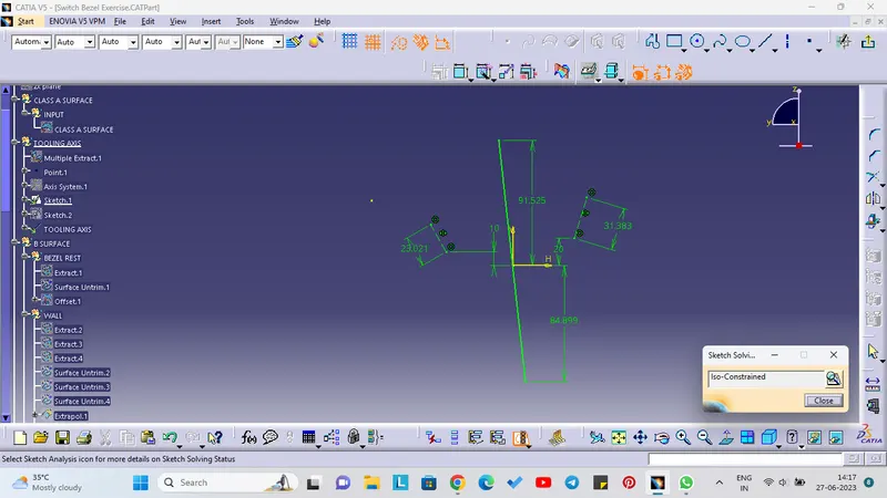
- Select the YZ plane and position Sketch
- choose Intersect 3D element and touch the class A surface, An horizontal intersect line will create.
- project the origin point to the extracted bottom surface.
- click line command (point to point) and touch both sides of 2 points which makes the draft angle.
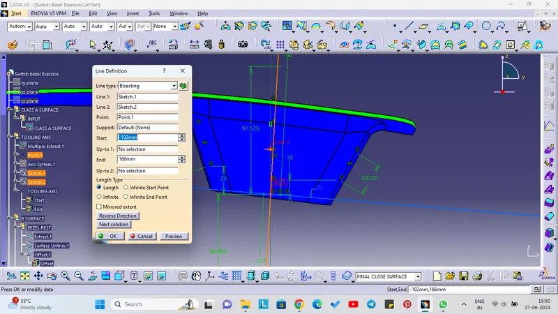
- Choose the bisecting Line command then touch both lines.
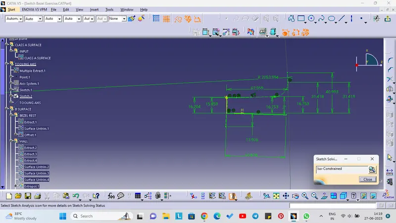
- Now, click the XZ plane and position sketch
- choose Intersect, and touch the class A surface, with the XZ plane. An intersect line will create on the class A surface.
- click line command (point to point) and touch one side of the wall on which draft analysis has to be done.
- click the line command and sketch the line on the XZ plane which will make 3 deg angle from the side wall.
- Now, We have the 2 Tooling axis.
- so for the exact tooling axis, we will use the bisection line method.
2. Draft analysis
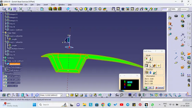
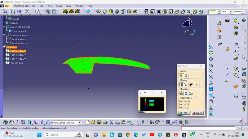
- Select the Feature Draft Analysis
- click the part and define the tooling Direction
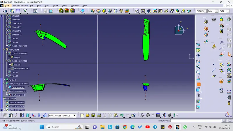
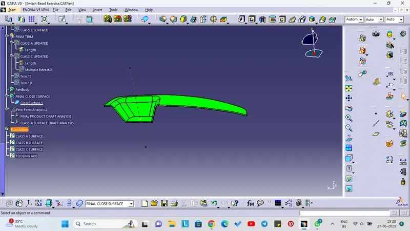
- Green Side is showing that the part will be made according to the Draft Angle which is 3 degrees and there will no erosion between the Tool and Plastic parts.
- The blue side is showing a negative Draft angle (interference) or is impossible to draw the part according to the draft angle.