Radar Mast & Final Assembly of Yacht
MODELING OF SUNSEEKER PREDATOR YACHT USING SOLID WORKS
OBJECTIVE :
To Create a surface model of different parts of the yacht using solidworks and to assemble the different parts modeled for the yacht.
Introduction :
In this project we learnt about designing a sunseeker predator yacht using soildworks. With the help of blueprint create asketch and dimensioning the each and every part of the sunseeker predator yacht. Aftetr creating parts of design we study about the assembley to create sunseeker predator yacht.
Designed parts are mentioned below:
- Propeller
- Radar
- Hull
- Garage Door
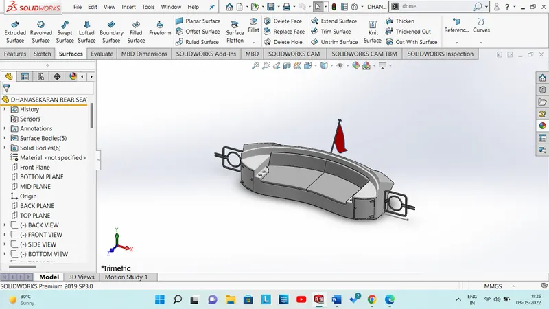
- Rear Seat
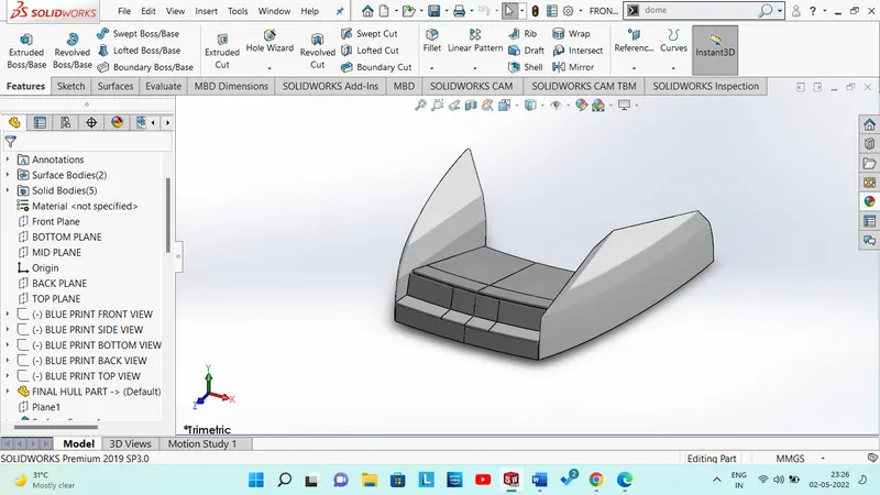
- Front Seat
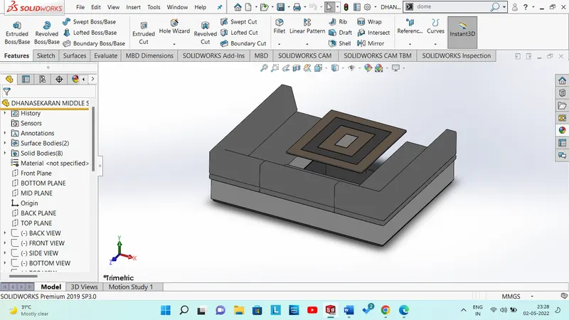
- Middle Seat
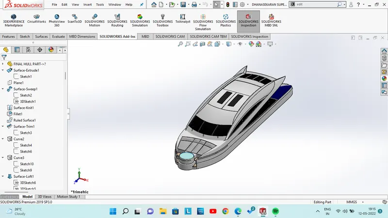
- Super Structure
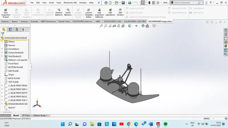
- Radar Mast
DESIGN METHODLOGY:

PROPELLER:
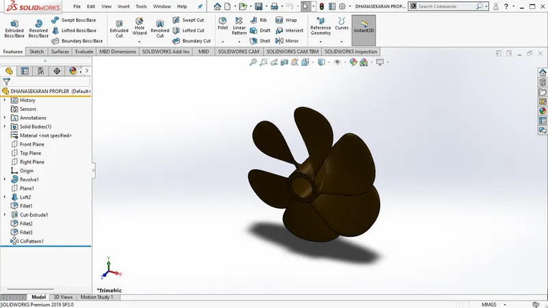
Propeller is used to propel the boat forward and the transmitted power is converted from rotary type to thrust to propel it.
RADAR:
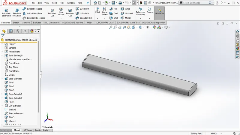
It is used to transmit and receive signals which is used in every ships.
BLUEPRINT :
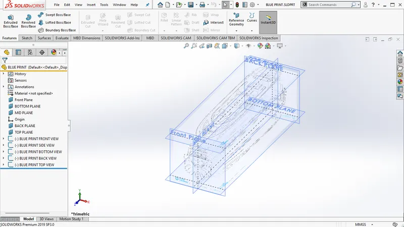
Blueprint is used to create basic sketch of part to design.
HULL :
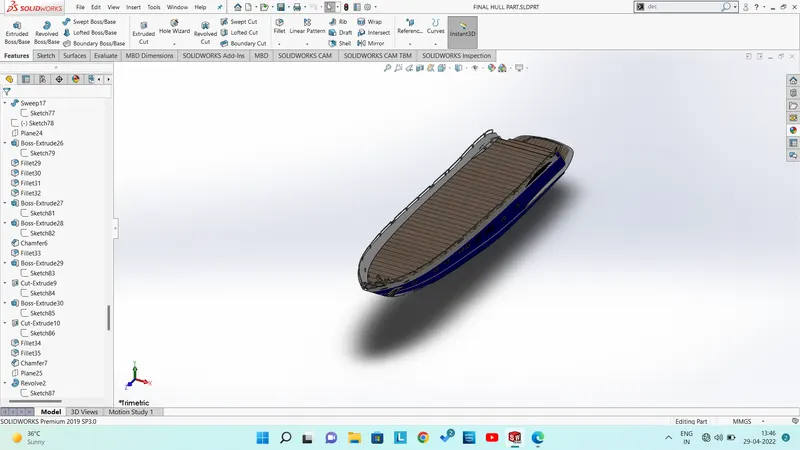
It can be said that it is the watertight enclosure of the ship, which protects the cargo, machinery, and accommodation spaces of the ship from the weather, flooding, and structural damage.
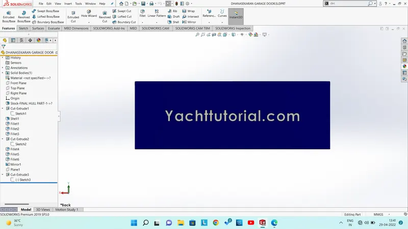
GARAGE DOOR :
Garage door attached behind operates with amotor or manually. It is used to store automobiles in yacht.
FRONT SEAT :
MIDDLE SEAT :
REAR SEAT :
SUPER STRUCTURE :
A superstructure is a decked structure on the freeboard deck, extending from side to side of the ship or with the side plating not being inboard of the shell plating.
RADAR MAST :
Electronic navigation instruments that use a rotating antenna to sweep a narrow beam of microwaves around the water surface surrounding the ship to the horizon, detecting targets by microwaves reflected from them, generating a picture of the ship's surroundings on a display screen.
DESCRIPTION :
BOSS BASE EXTRUDE :
Extrude tool is used to extend a sketched profile in one or two directions as either a thin feature or a solid feature.
EXTRUDE CUT :
Extruded cut feature removes material from the part. The End Condition, Draft, and Thin Feature options are same as described in Extruded Boss/Base. To create an extruded cut.
LINEAR PATTERN :
Use linear patterns to create multiple instances of one or more features that you can space uniformly along one or two linear paths.
FILLET :
Fillets describe rounded corners of a design that help to reduce stresses and prevent rapid deformation at the corners of the part.
CHAMFER :
In contrast, chamfers are sloped or angled edges (usually at 45° or 60° ) of a design or part.
SWEEP BOSS/BASE :
Sweep is the one feature in Solidworks that helps sweep a closed profile along a closed or open path. In this session, we are going to use a simple 3D object as an exercise to demonstrate.
SWEEP SURFACE :
Sweep Surfaces are surfaces that are generated from a section curve positioned along a path.
DOME :
Dome creates a dome that is tangent to the adjacent cylindrical or conical face.
HELIX :
The curve can be used as a path or guide curve for a swept feature, or a guide curve for a lofted feature.
DELETE FACE :
It is used to easily remove faces from solid or surface bodies.
REVOLVE :
Revolve is a method of defining three-dimensional geometry by revolving a sketched section around a centerline.
COMBINE :
It is used to add two or more solid and surface bodies into a single body.
SURFACE EXTRUDE :
Surface Extrude feature, we can extrude the boundary edges of a face of a solid body or edges of a surface body in a customized direction.
SURFACE EXTEND :
Under Edges/Faces to Extend, select one or more edges or faces in the graphics area for Selected Face/Edges. For edges, the surface extends along the plane of the edge. For faces, the surface extends along all edges of the face except those connected to another face.
TRIM SURFACE :
Create two or more surfaces that intersect at one or more points, or create a surface that intersects with a plane or has a sketch on its face.
OFFSET SURFACE :
The offset surface tool is useful way of creating a series of deposit or erosion contact surfaces from a reference mesh
KNIT SURFACE :
Knit surfaces used to merge two or more surface into a single surface with a kniting tolerance.
MIRROR:
Create an opposite-hand version of a part. In a part select a face or plane to mirror about.
SPLIT LINE :
Tool projects an entity (sketch, solid, surface, face, plane, or surface spline) to surfaces, or curved or planar faces. It divides a selected face into multiple separate faces.
CIRCULAR PATTERN:
A circular pattern is an radial arrayof objects around a. Center point in a sketch. Axis in a part or assembly.
FILL SURFACE :
The Filled Surface feature constructs a surface patch with any number of sides, within a boundary defined by existing model edges, sketches, or curves, including composite curves.
LOFT SURFACE :
Loft Surfaces are surfaces generated by multiple 3D Curves or existing edges creating a smooth tangency between the selected curves.
BOUNDARY SURFACE :
A boundary spans two or more profiles in one or two directions. A boundary can be a base, boss, cut, or surface. Boundaries follow the profiles specified in Direction 1 (blue) and Direction 2 (purple). The Boundary Surface feature can create surfaces that span the extents of Direction 1 and Direction 2.
SHELL :
The shell tool hollows out a part, leaves open the faces you select, and creates thin-walled features on the remaining faces. If you do not select any face on the model, you can shell a solid part, creating a closed, hollow model.
ASSEMBLY :
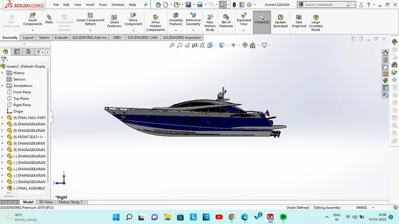
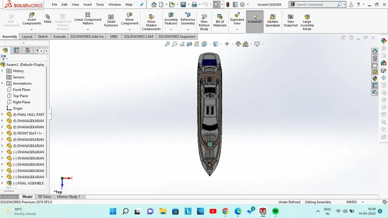
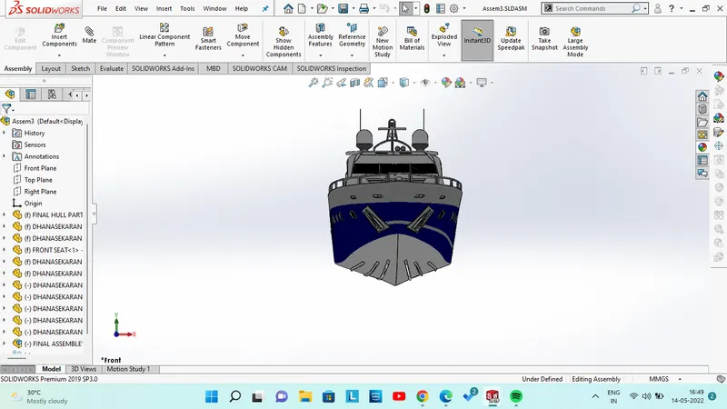
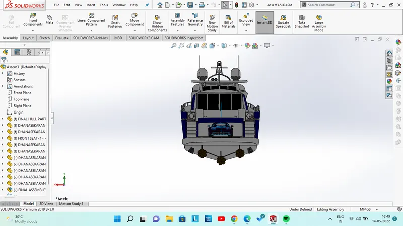
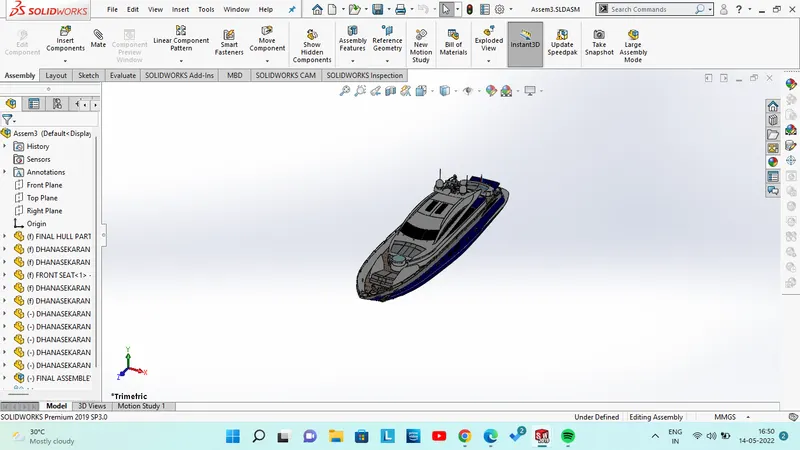
To build complex assemblies consisting of many components, which can be parts or other assemblies, called subassemblies. For most operations, the behavior of components is the same for both types. Adding a component to an assembly creates a link between the assembly and the component.
RENDERING :
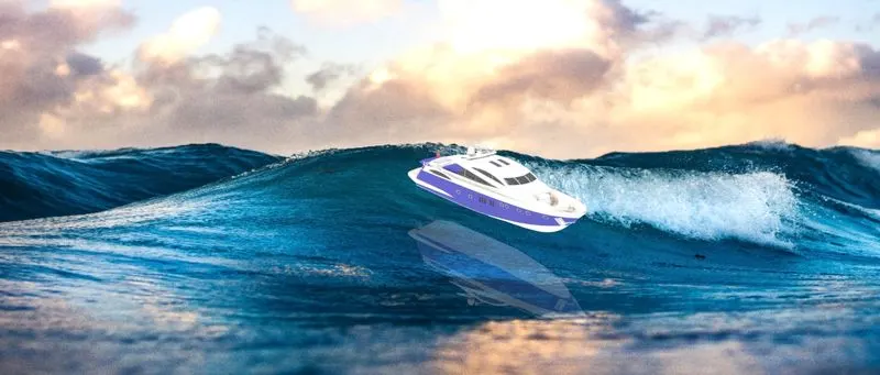
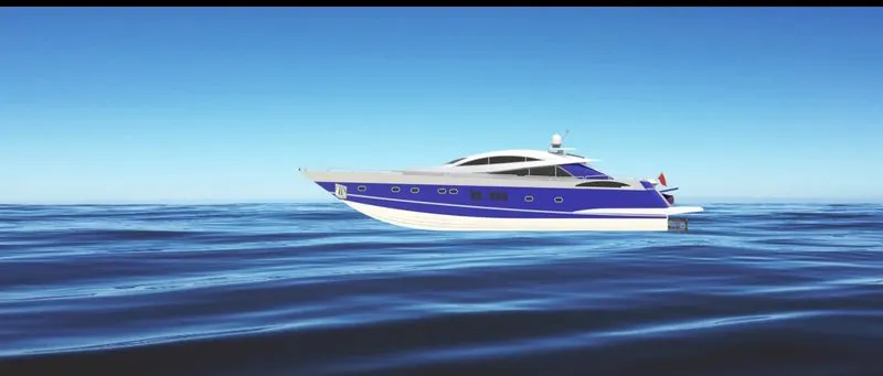
CONCLUSION :
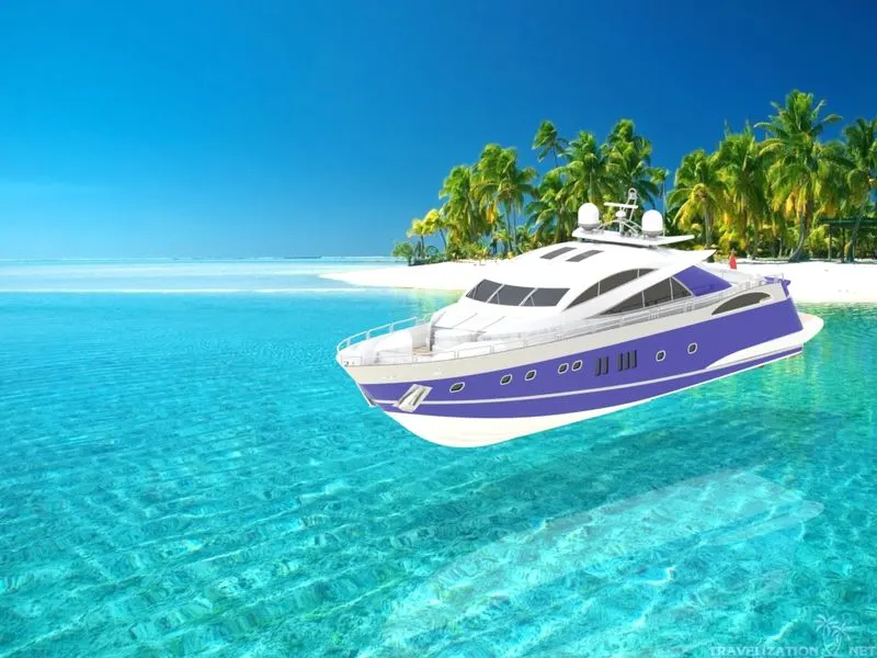
The Sunseeker Predator Yacht helped us to understand different portion of solidworks such as solid modelling, surface modelling, assembly modeling, rendering etc.