Assignment 7-Side Pole Crash Simulation Challenge
AIM: To create deck setup for side crash of car BIW and request for time plots.
OBJECTIVE:
- Check unit system and either follow [Mg mm s] or [Kg mm ms].
- Create appropriate interface ,friction 0.2 and recommended parameters.
- Make sure of no penetration and intersections.
- Create rigid wall with friction 0.1 as per referance model.
- Compare the model weight with the referance model and use added masses to reach target weight 700kg while getting CG about the required range.
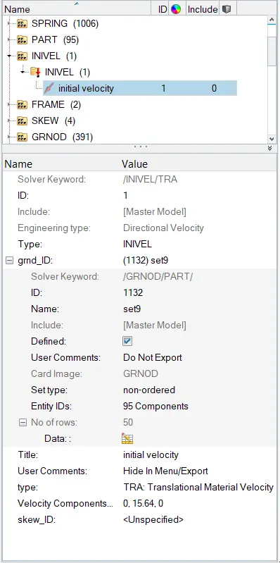
- Initial velocity as shown in picture.
- Use model checker to ensure good quality.
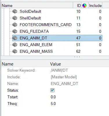
- Timestep :0.5 to 0.1 microseconds.
- Run 80ms.
Output requests:
- Sectional force in the cross member.
- Intrusion at B pillar,hinge pillar and fuel tank region.Provide recommendation on what can help to reduce Fuel tank intrusion.
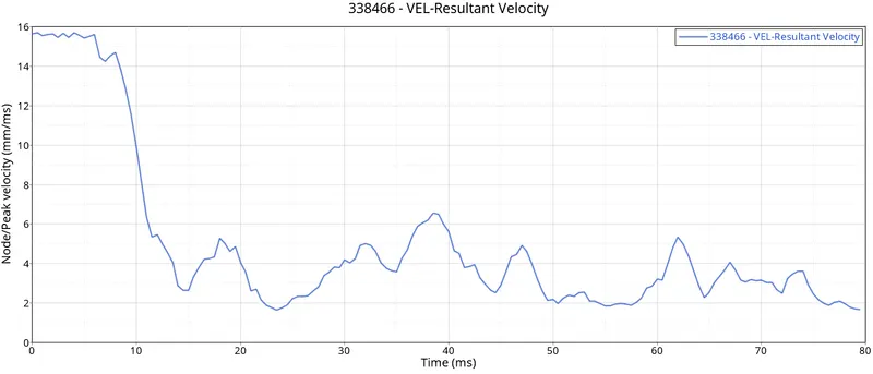
- Peak velocity of inner node of the door.
Case set-up and execution
Import the given model:
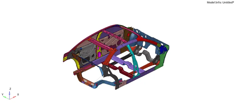
Check unit system and either follow [Mg mm s] or [Kg mm ms].
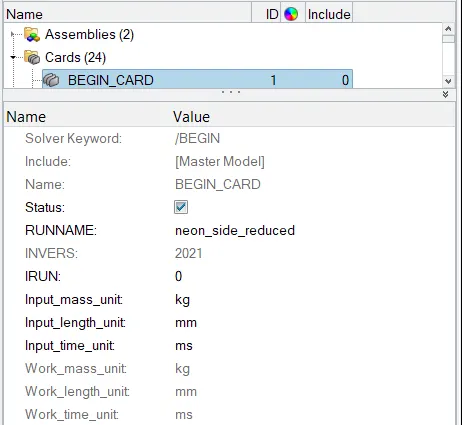
Go to Model Browser >>> Cards >>> Begin Card >>> Check for the units.
The unit system followed is Kg-mm-ms.
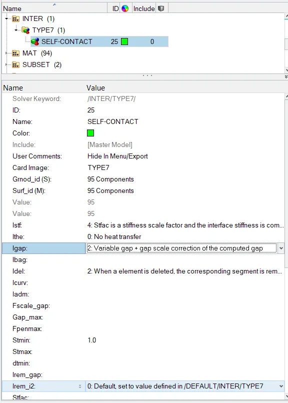
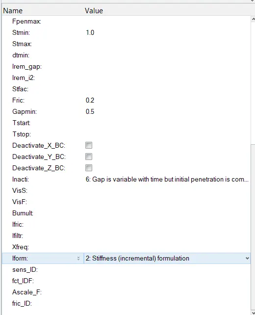
2.Create appropriate interface ,friction 0.2 and recommended parameters.
Type 7 contact is used with all recommended properties and with friction value of 0.2
For both slave and master, all 95 components are selected.
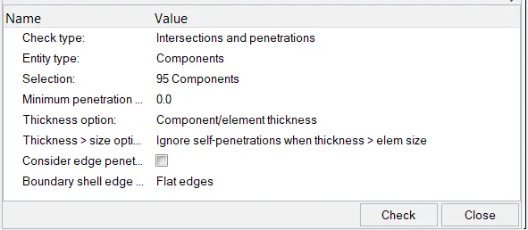
3. Make sure of no penetrations and intersection.
Go to Tools >>> Penetration Check >>> select check type as Intersections and Penetrations >>> Select all components >>> Check
The outpue result is: All interfaces check is completed: 0 collisions Found.
4.Correct rigid bodies if any issues.
As there are no penetrations and intersections, there is no issue with rigid bodies.
5. Create rigid wall with friction 0.1.
Go to Solver deck >>> Right click >>> create >>> Rwall >>> Cylinder.
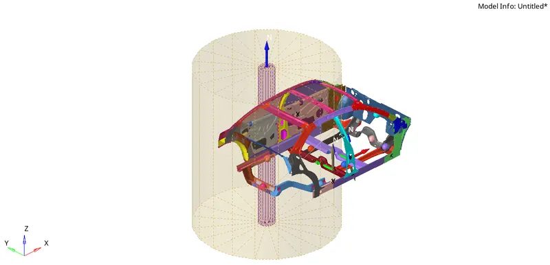
Select any node on the B-pillar and change the y-cordinate such tht a gap is maintained.
Provide normal in z-direction.
Prove the sliding friction with value of 0.1 and dsearch = 1000.
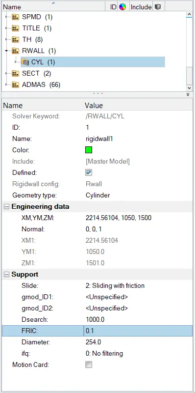
The nodes that are part of dsearch act like slave nodes.
6. Compare the model weight with the full scale 300k nodes model and use added masses to reach target weight 700kg while getting CG about the required range.
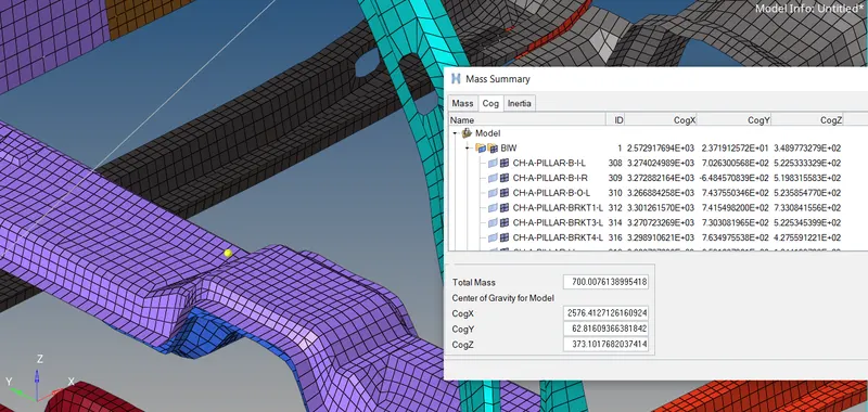
Check the mass and COG point:
Go to tools >>> Mass details >>> Mass, COG and inertia
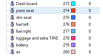
Add mass in the form of seat and dummy to get 700 kgs and desirable COG point.
Go to solver deck >>> Right click >>> ADMAS >>> Select the nodes on which the mass should act >>> Provide the value of mass.
The below image shows the points to which mass is added.
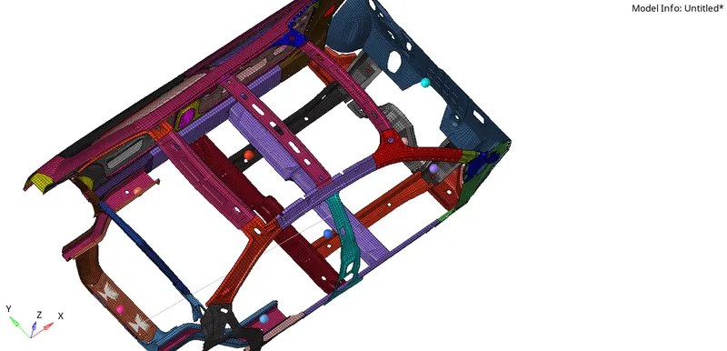
The increse in weight to 700kgs is by adding the respective components as shown below.
The COG point is shown below (representing cog in yellow)
7. Initial velocity 35 mph.
Go to Solver deck >>> Right click >>> Create Inivel >>>Select all components and provide the value of velocity.
8. Time-step :0.5 to 0.1 microseconds.
Model browser >>> Cards >>> Anim_Dt >>> Tfreq = 5.
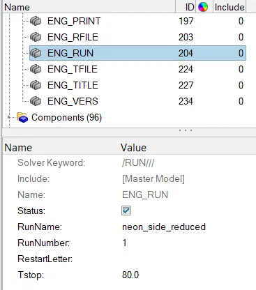
9. Run 80 ms.
Model browser >>> Cards >>> Eng_Run >>> Tstop = 80.
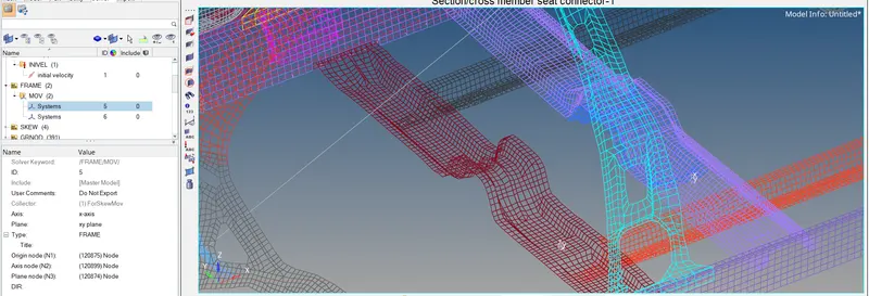
10. Create frames at each cross-section where forces are to be calculated.
Go to solver deck >>> Right click >>> Create Frame >>> select N1, N2, N3 such that N1 and N2 are making x-axis and N3 x-y plane.
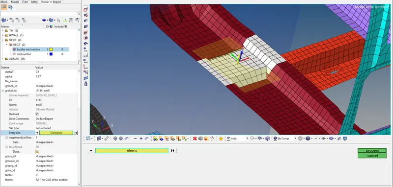
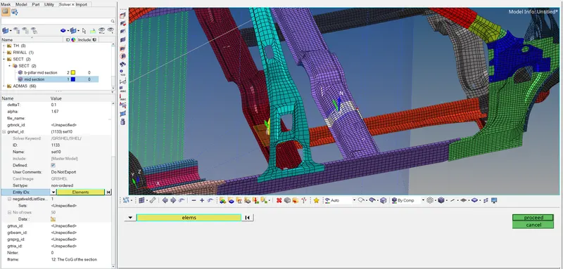
Create Sections at which cross-sectional forces are to be determined.
Isolate the respective component and create the section by selecting the respective elements and choose the respective frame in the frame id and set iframe = 12, the cog of the section.
Intrusion at B-pillar, Hinge pillar and fuel tank region:
Create skew at the location opposite to the point where intrusions are to b calculated.
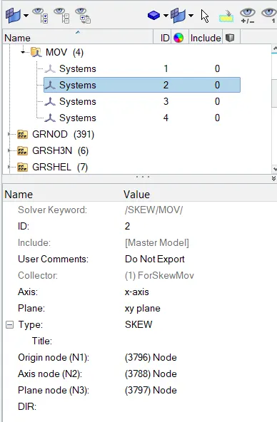
Create Intrusions in Output-Block:
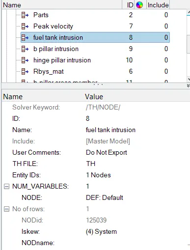
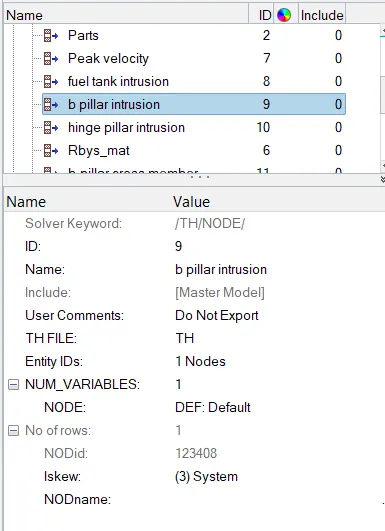
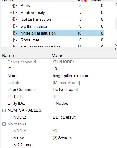
Go to model browser >>> Output block >>> Create >>> Add the name and node on the respective component >>> select the skew.
Fuel tank intrusion:
B-pillar intrusion:
Hinge pillar intrusion:
Peak velocity of inner node of the door:
Create the skew at the location where peak velocity is to be calculated.
Go to output block, create >>> Add name and the node >>> add the skew.
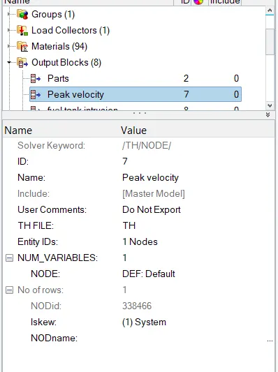
Output block:
Add sectional forces in output block and provide the respective component cross-sections.
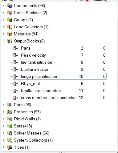
Results:
Go to Analysis >>> Radioss >>> Save the file >>> Include connectors >>> Prove the number of threads in options >>> Run.
Open Hyper View >>> Import the H3D file
The Animation is shown below:
From the simulation, we can review how the impact force acts and causes the deformation in the model.
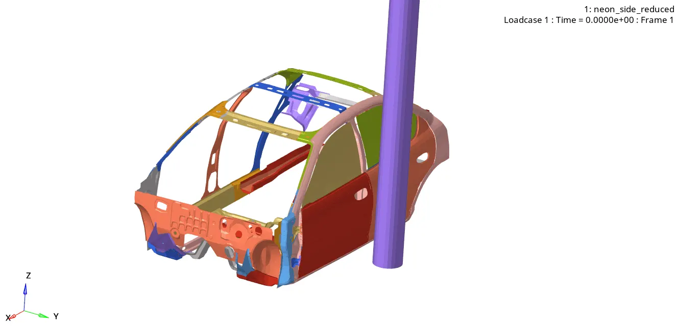
From the simulation, we can see that initially when car hit the rigid wall with a velocity of 15.64 m/s. The primary contact is with b-pillar and the forces due to impact are then transferred to the roof rail, cross-members. hence the forces in each stage are getting reduced as the energy is obsorbed by the components in the form of deformation.
The displacement Contour is shown below:
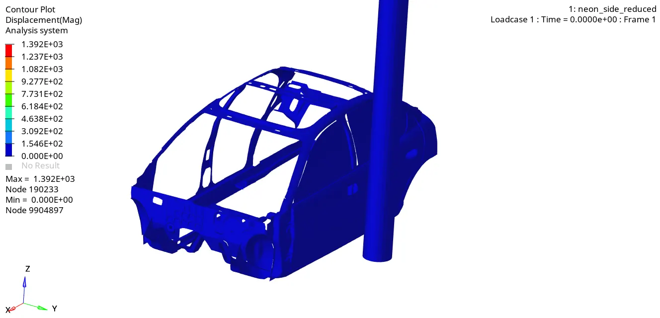
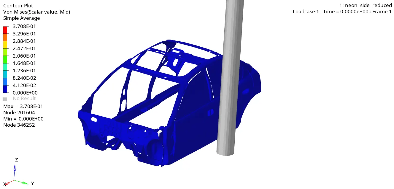
The Von-Mises stress is shown below:
Open 0001.out file to check whether results would be acceptable.
The positive energy error indicates the add in mass to the component to maintain the critical time-step.
If there is a larger positive energy creation, the source of energy has to be identified. Incompatibility may lead to this.
Observation:
The energy error is negative and maximum = -2.4%, which is acceptable.
the mass error is quite less, and is acceptable.
we can see the increase in internal energy and decrease in kinetic energy from 0th cycle to 80001th cycle.
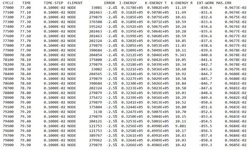
The output file contains the data related to simulation i.e., Cycle time, Time step, Energy and Errors.
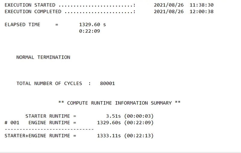
The time taken for the simulation = 1333.11 seconds
number of cycles = 80001.
Energy graph:
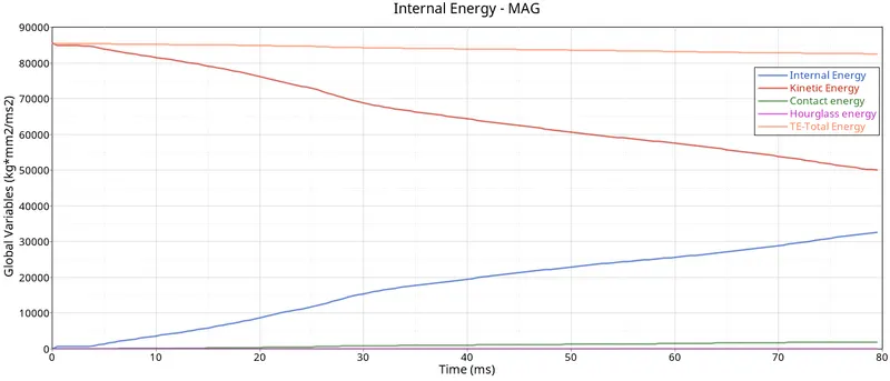
Graph above shows the Internal energy, Kinetic Energy, Hourglass energy, Total energy,Contact energy.
Hourglass energy is almost zero and is stabilized by using the recommended properties.
We can see at the start of simulation the internal energy is minimum and K.E is max, as the deformation is taking place Internal energy increases and kinetic energy decreases thereby maintaining the total energy as constant.
The maximum Kinetic Energy is at t=0 i.e., 85576.9 J
The maximum Internal Energy is at t=79.5 sec i.e., 31806.4 J
Contact energy is the energy that is imposed to resist the penentration, we have determined the min gap value to 0.5. As the deformation takes place, the contact energy increases gradually.
Max. Contact energy is at 79th second = 1900 J
Sectional Forces in cross members:
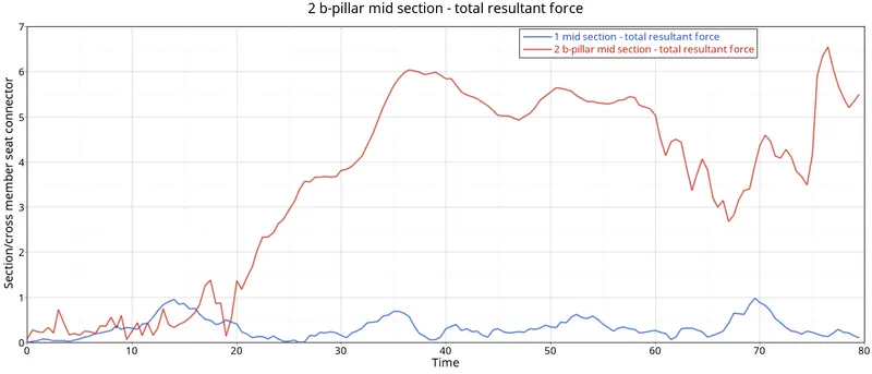
The cross members are the parts that transfers the force from one end to the other side when the impact occurs.
The maximum sectional force in the b-section pillar is 6.5 KN.
The maximum sectional force in the driver cross beam is 1 KN.
When the car hits the rigid pole, the force is transferred from tyhe b-pillar to the cross members and the other side.
From the above graph, we can see the rise in the force due to force acting on the cross members due to this force passing through the cross members get bent and the force gets reduced there on. Even though the force drops, it won't be zero, in the animation we can see the bend of cross members again gets deformed so the curves are seen increasing and decreasing.
Intrusions:
Intrusions are one of the important parameters in crash analysis. we have created the skews at the fuel tank, b-pillar and hinge pillar on other end of impact and created the intrusion by selecting the nodes on the side of impact and their respective skews in the Output block requesting the output file.
Green plot - Hinge pillar intrusion
Red plot - B-pillar intrusion
Blue plot - Fuel tank intrusion
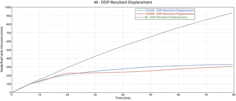
The initial distance b/w the hinge pillars is 1309 mm. The final distance b/w the hinge pillars due to impact is 940mm, we can see the intrusion of the hinge pillar is 360 mm.
The intrusion of the fuel tank and b-pillar are around 950 mm and 980 mm.
The fuel tank and b-pillar components are seviourly deformed which is not acceptable.
But in real case scenario, there are many components like Rear axle and many other components which reduce the intrusions to ensure safety.
Peak velocity:
As the impact takes place at time t=0, the force is transmitted from b-pillar to the inner part of the door and hit the passenger inside the car and leading to injuries. Hence, it is important that the peak velocity is to be considered while designing.
From the graph we cann the maximum velocity is 15.8 m/s.
The decrease in trend is due to transmitting the force to neighbouring components and the shock wave is due to the vibrations that occured during crash.
Recommendations on what can help to reduce fuel tank intrusions:
We can make the components surrounding less stiffer so that as the impact happens, the surrounding components gets deformed there by absorbing the energy. Which helps in reducing the fuel tank intrusion.
We can use some coating on the fuel tank which increases its stiffness thereby decreasing the deformation.
Learning Outcomes:
- Learned how to set up a deck for side crash.
- Learned how the sectional force are generated.
- Learned how to ensure the safety to passengers and how forces are transmitted through the components.
- Learned how to check: energy errors, mass errors momentum, energy balancing.
- Learned how to request the outcomes.
Conclusion:
The given model is simulated for side crash using Radioss and the results are obtained. From the results we can observe how the deformation is taking place and how the forces are distributed through the components. We didn't use all the components of the model due to student edition which is limiting the usage of number of nodes. We can take respective measures to keep the intrusion value to minimum to ensure safety.