Assignment 7-Side Pole Crash Simulation Challenge
SIDE CRASH ANALYSIS WITH NEON DODGE MODEL
AIM:
The main aim is to perform side crash analysis in the neon model with the recommended parametres and output requests.
- Check unit system and either follow [Mg mm s] or [Kg mm ms].
- Create appropriate interface ,friction 0.2 and recommended parameters.
- Make sure of no penetration and intersections.
- Create rigid wall with friction 0.1 as per referance model.
- Compare the model weight with the referance model and use added masses to reach target weight 700kg while getting CG about the required range.
- Initial velocity as shown in picture.
- Use model checker to ensure good quality.
- Timestep :0.5 to 0.1 microseconds.
- Run 80ms.
OUTPUT REQUESTS:
- Sectional force in the cross member.
- Intrusion at B pillar,hinge pillar and fuel tank region.Provide recommendation on what can help to reduce Fuel tank intrusion.
- Peak velocity of inner node of the door
PROCEDURE:
The unit system is confirmed from the BEGIN_CARD and throughout this analysis the carried out unit convention is kg mm ms.
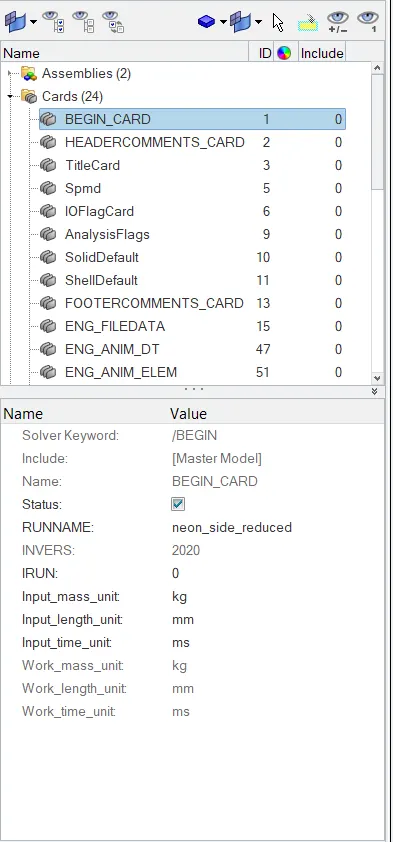
FIG 1. UNIT SYSTEM CONFIRMATION
INTERSECTION & PENETRATION CHECK.
The intersection and penetration check is made to get rid of results get affected. Open Tools > Penetration check in Hypermesh.
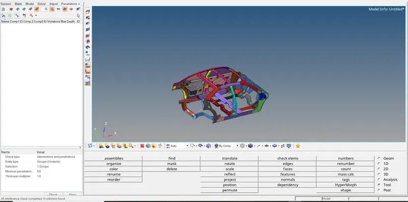
FIG 2. INTERSECTION & PENETRATION CHECK
INITIAL VELOCITY:
For this model an initial velocity of 15.6464 mm/ms (35mph) is applied to the car model to initiate the crash sceneraio. Right click on the Tool bar inside solver deck and select Intial velocity option under Boundary condition. It is applied in Vy direction perpendicular to rigid wall.
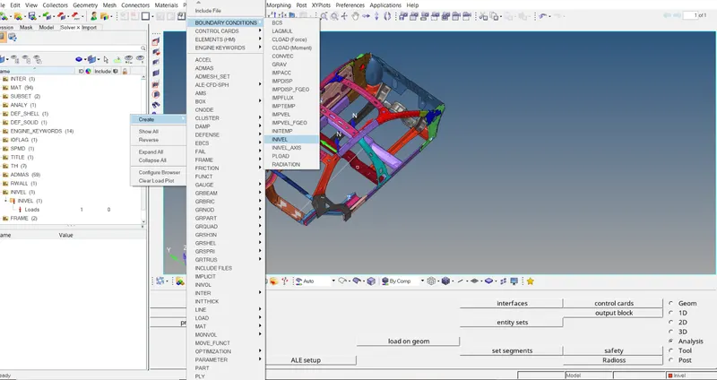
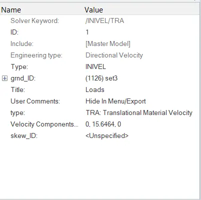
FIG 3. INITIAL VELOCITY FIG 4. VELOCITY CARD
CONTACT INTERFACE:
Make connection with type7 to represent Self contact with recommended parameters by deleting the already created 6 contacts. Friction for this contact is taken as 0.2 mm.
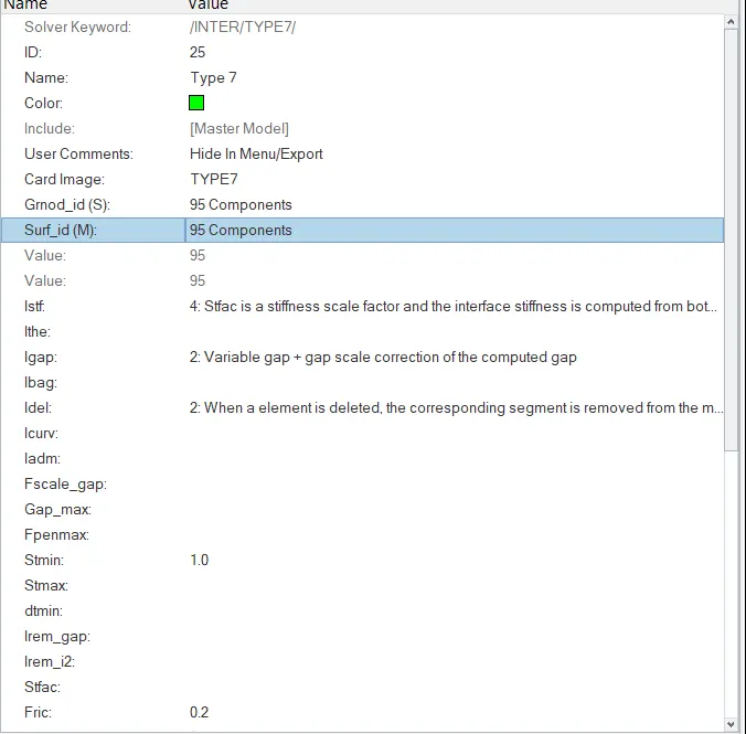
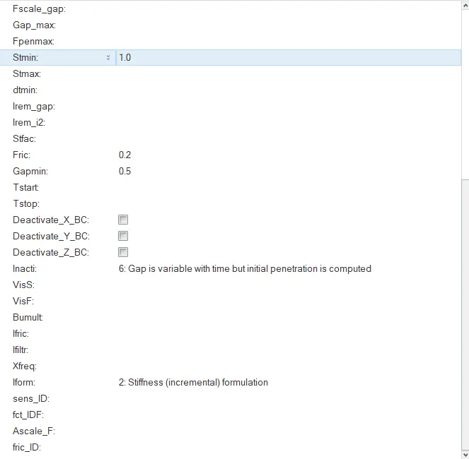
FIG 5. INTERFACE CARD FIG 6. INTERFACE CARD
RIGID WALL:
The rigid wall is created at the b-pillar section for representing the wall properties for the crash. Here Dsearch value is taken as 1000 mm & Dia is 254 mm with friction 0.1 mm to search for slave nodes.
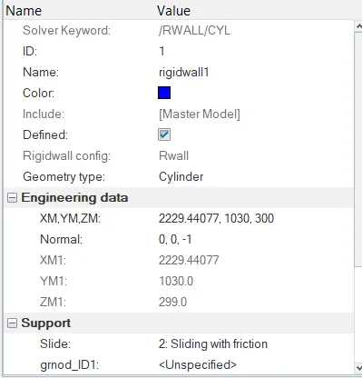
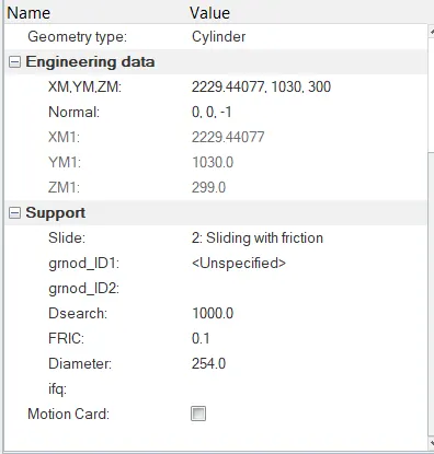
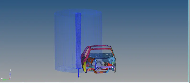
FIG 7. R-WALL CARD FIG 8. R-WALL CARD FIG 8. R-WALL REPRESENTATION
MASS BALANCING:
Initially the mass of the model is 166 kg, in order to represent the scaled model into full car model, the mass is converted to 700 kg. Right click on the Solver deck and craete Admas card to add mass to the model.
Additional mass of 53.4 Kg is added to each node as highlighted, so that full car model is represented and we have COG located exactly near the driver Seat as recommended.
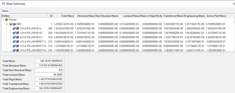
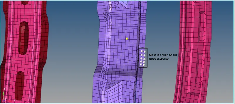
FIG 9. INITIAL TOTAL MASS FIG 10. ADDED MASS
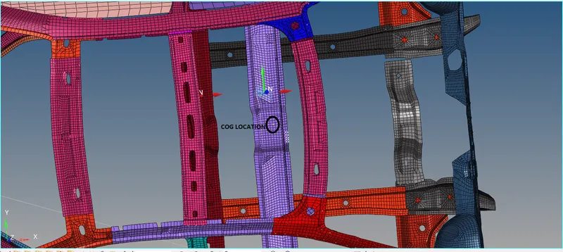
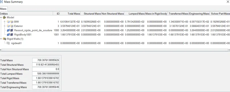
FIG 11. COG RECOMMENDED LOCATION FIG 12. TOTAL RECOMMENDED MASS(700 Kg)
TIMESTEP & ENGINE RUN CARD:
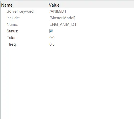
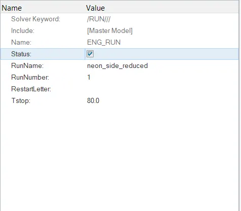
FIG 12.1 TIMESTEP CARD FIG 12.2 ENGINE RUN CARD
FRAME CREATION:
Create a frame which is movable at both the cross members to study the effects of force on them respectively.
Select N1 (Origin node), N2 (Axis Direction), N3 (Plane at frame should be created).

FIG 13. FRAME CREATION
Select the highlighted elements for goup shell elements and select proceed button.
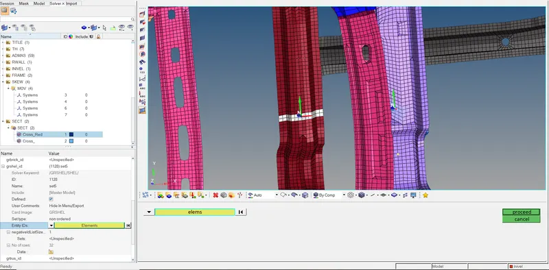
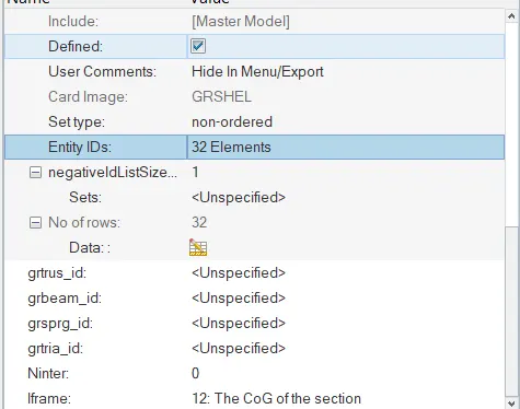
FIG 14. SECTION CREATION FIG 15. SECTION CARD
Select the frame created in the Frame ID for the respective cross section. Use Delta as 0.1mm and alpha as 1.64mm. Here Iframe = 12. Hence the necessary cross section is created to analyse the effect of forces.
SKEW CREATION:
Create Skew at B-pillar, Hinge pillar and fuel tank region.
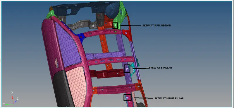
FIG 16. SKEW CREATION
OUTPUTBLOCK:
Create output blocks for hinge & B-Pillar, cross section, fuel region and inner side door.
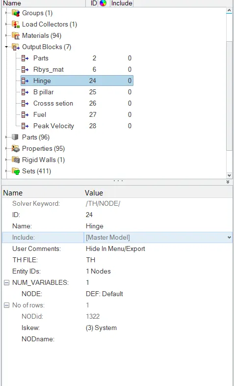
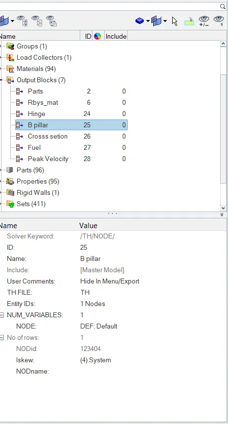
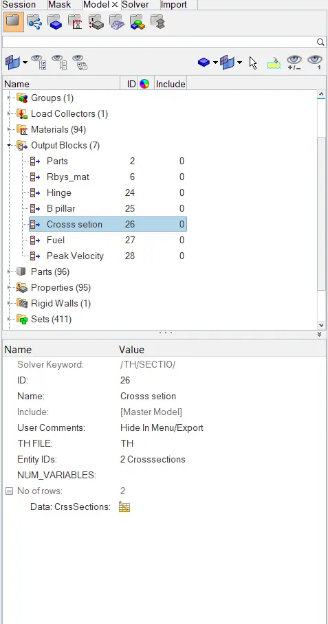
FIG 17. HINGE PILLAR CARD FIG 18. B-PILLAR CARD FIG 19. CROSS SECTION CARD
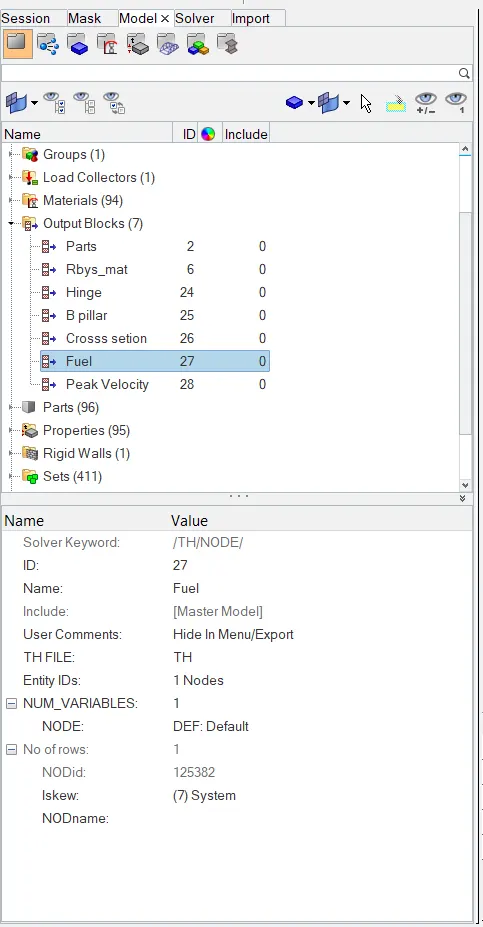
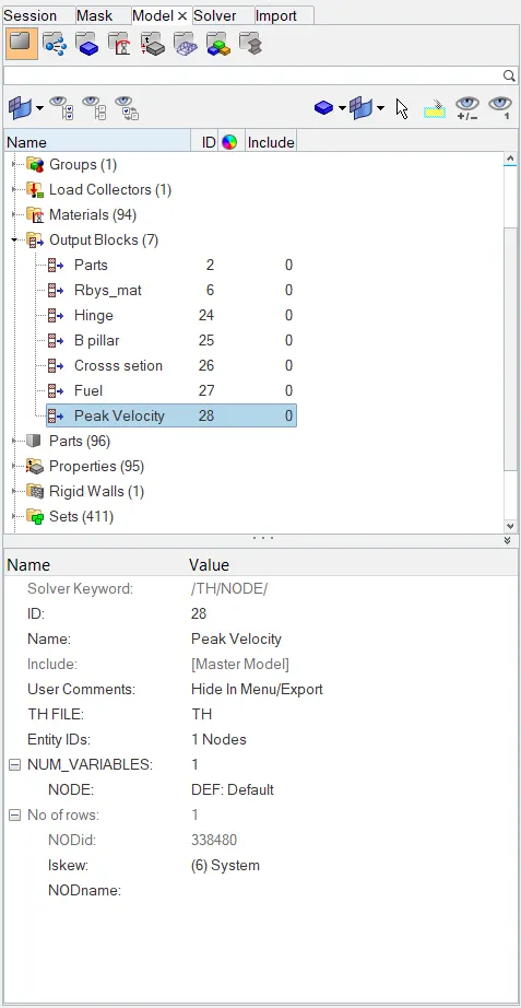
FIG 20. FUEL REGION CARD FIG 21. INNER SIDE DOOR CARD
Before starting to run the simulation, it is necessary to check for error in the model. For this use Tools > Model Checker > Radioss Elements.
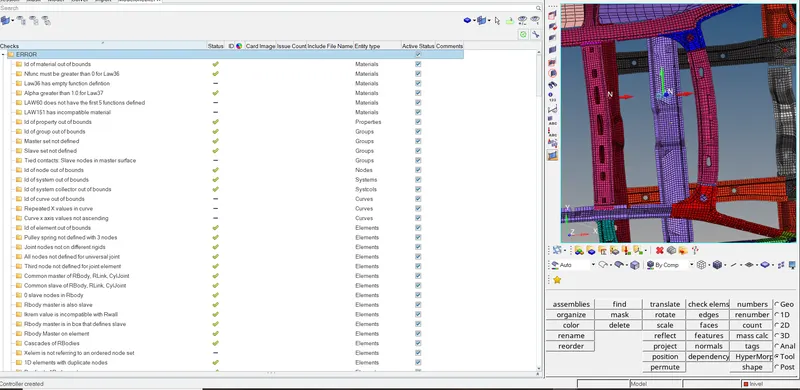
FIG 22. MODEL CHECKER
The simulation ran for 80001 cycles. Energy error is -1.3 % which is acceptable. Mass error is 1.08 % which is also less then 5 % and is under control as per the simulation.
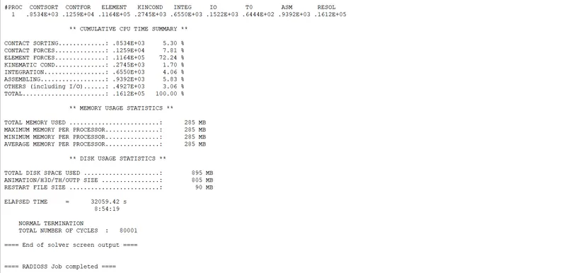
FIG 23. NUMBER OF CYCLES
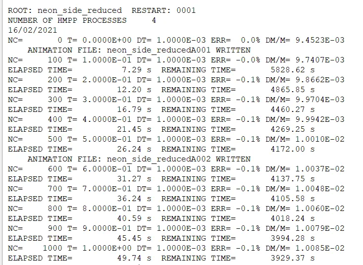
FIG 24. neon_side_reduced_0001.OUT FILE (STARTING STAGE)
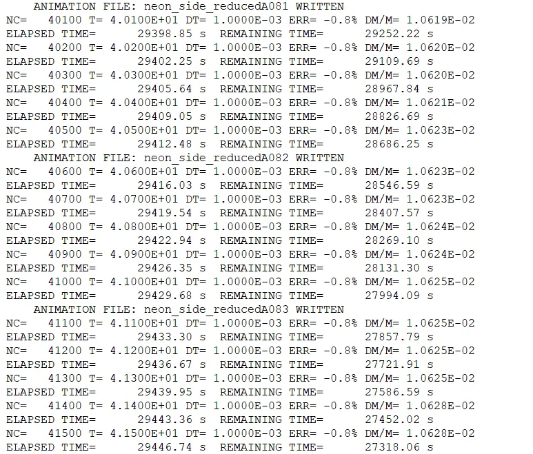
FIG 25. neon_side_reduced_0001.OUT FILE (MIDDLE STAGE)
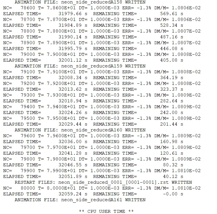
FIG 26. neon_side_reduced_0001.OUT FILE (FINAL STAGE)
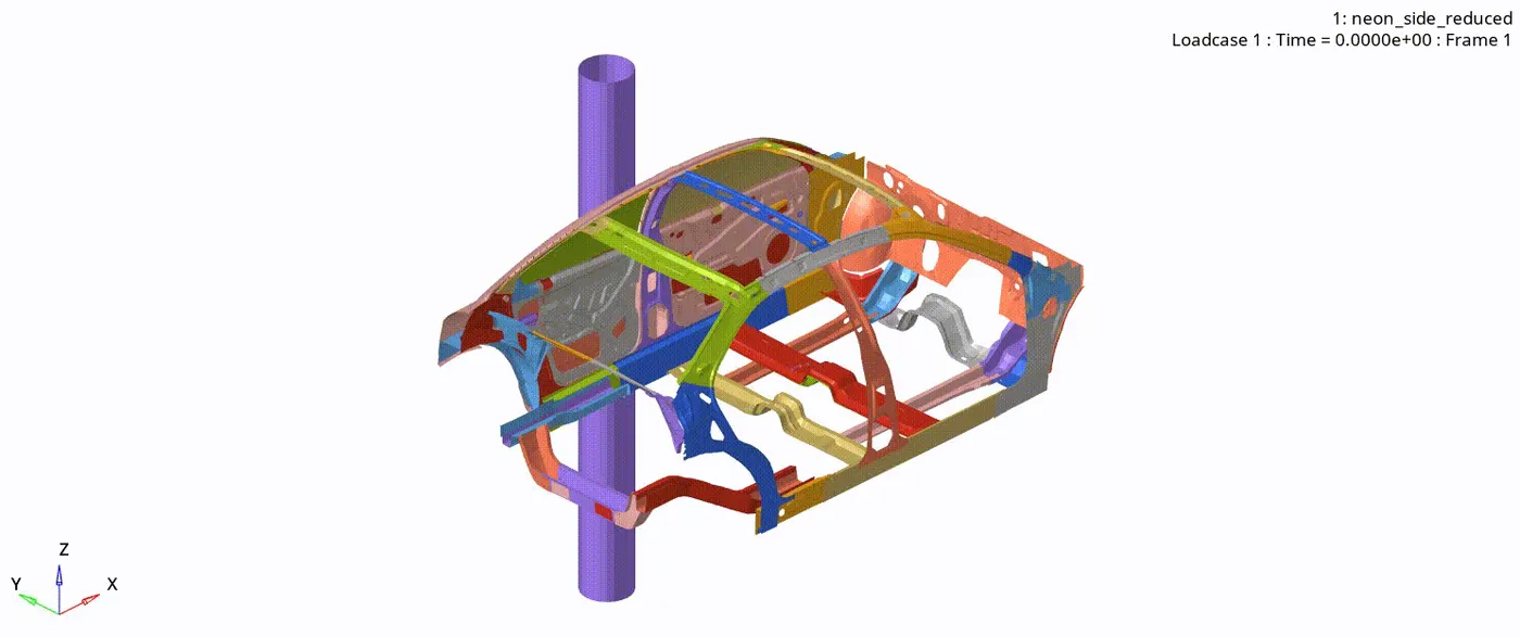
FIG 27. SIDE CRASH
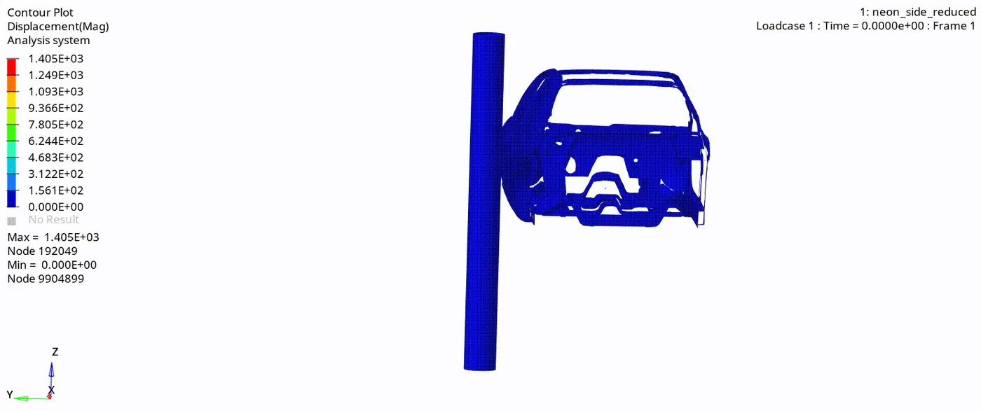
FIG 28. DISPLACEMENT CONTOUR
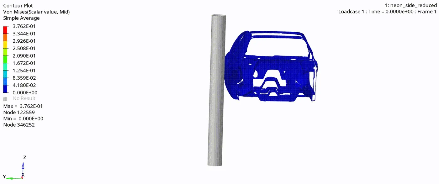
FIG 29. VON MISES STRESS CONTOUR
RESULTS & CONCLUSION:
INTRUSION AT HINGE PILLAR:
The intrusion at hinge pillar is calculated, between node 1322 and 3744. The intruded distance into the cabin is 1308 - 872 = 436 mm. Intrusions are calculated by using measure option.
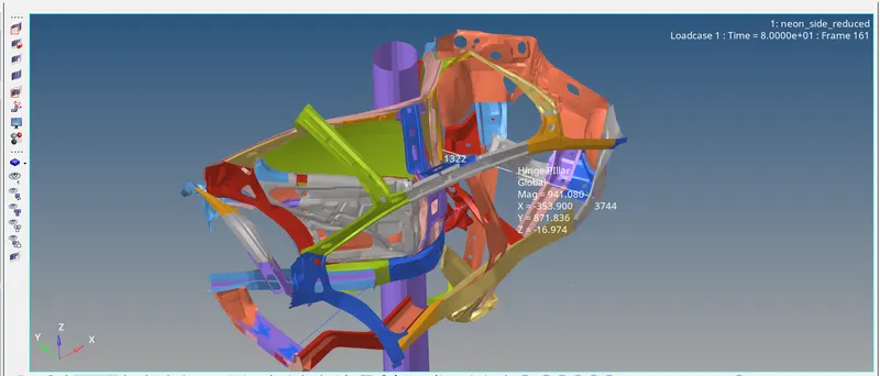
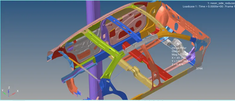
FIG 30. INTRUSION AT HINGE PILLAR FIG 31. BEFORE INTRUSION AT HINGE PILLAR
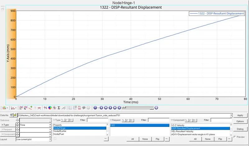
FIG 32. HINGE PLOT
INTRUSION AT B-PILLAR:
The intrusion at hinge pillar is calculated, between node 123404 and 124536. The intruded distance into the cabin is 1325 - 378 = 947 mm.
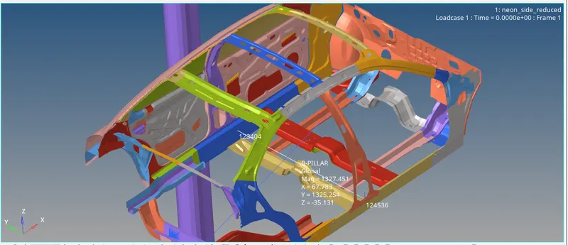
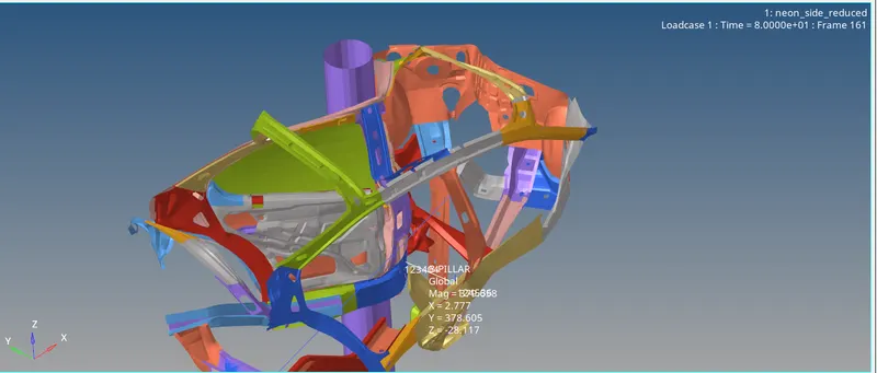
FIG 33. BEFORE INTRUSION AT B PILLAR FIG 34. INTRUSION AT B PILLAR
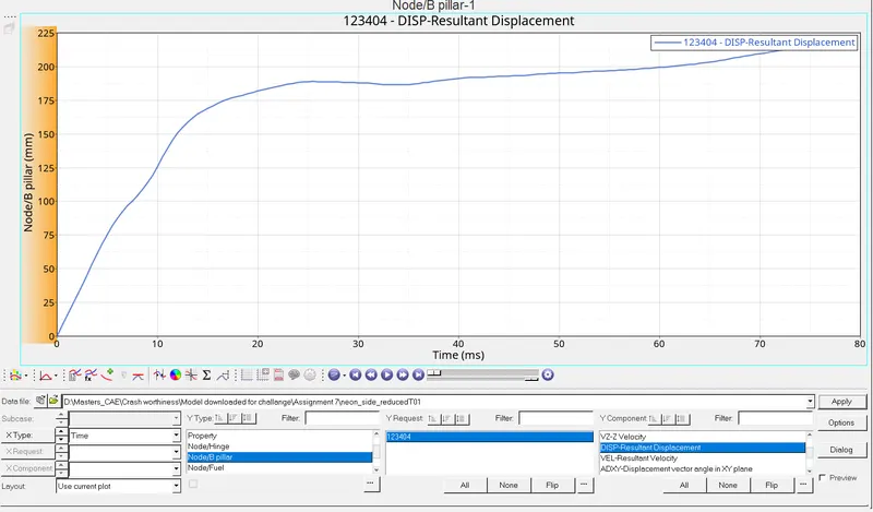
FIG 33. B-PILLAR PLOT
INTRUSION AT FUEL TANK REGION:
The intrusion at hinge pillar is calculated, between node 215252 and 125382. The intruded distance into the cabin is 1184 - 348 = 836 mm.
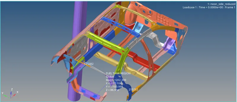
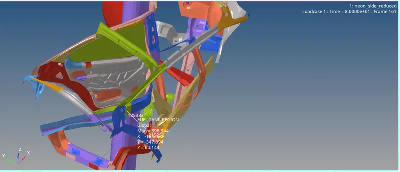
FIG 34. BEFORE INTRUSION AT FUEL TANK REGION FIG 35. INTRUSION AT FUEL TANK REGION
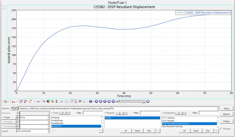
FIG 34. FUEL TANK REGION PLOT
SECTIONAL FORCE ON CROSS MEMBER:
The first cross member from the driver cabin, deforms more and absorbs more energy during the crash compared to the other one. This is due to the deattachment of the member attached to the cross member.
Max Sectional force is 1.36 KN
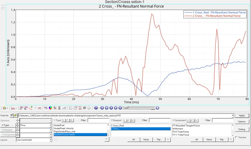
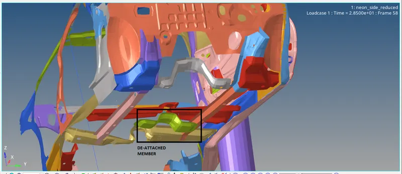
FIG 35. CROSS SECTIONAL FORCE FIG 36. DE-ATTACHED MEMBER
PEAK VELOCITY OF INNER DOOR:
The peak velocity remians constant initially, since the car is moving towards the pole before crash. After crash, the velocity increases @ 6ms and reaches the max of 16.2 mm/ms, then gradually reduces. After 14 ms, the velocity fluctuates between 3.36 mm/ms - 1.8 mm/ms.
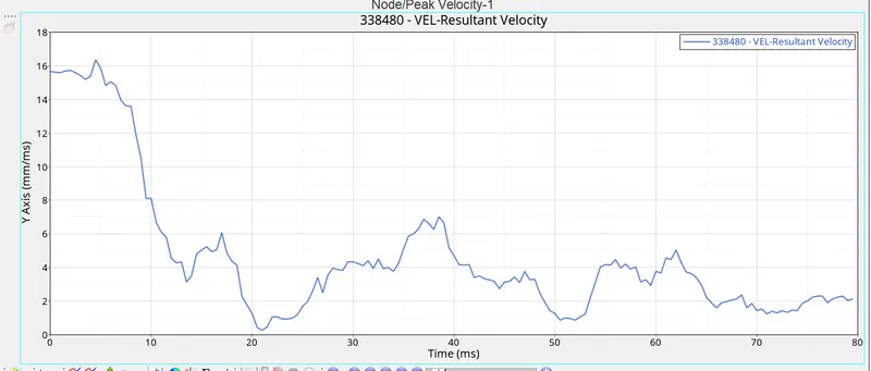
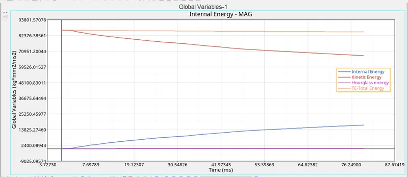
FIG 37. PEAK VELOCITY OF INNER DOOR FIG 38. ENERGY CURVE
METHODS TO REDUCE INTRUSION AT FUEL TANK REGION:
By adding extra cross members to increase the stiffness factor near the fuel tank region and introducing some composite alloys in the materials one can reduce intrusion in the fuel tank.
NOTE: Due to space consistency while uploading the whole model, I have attached only Starter, Engine RAD file and T01 File for grading purpose.