Assignment 7-Side Pole Crash Simulation Challenge
WEEK - 7
SIDE POLE CRASH SIMULATION CHALLENGE
OBJECTIVE:
- To check the unit system in the 0000.rad file and use consistent units throughout.
- To create appropriate interfaces for the model.
- To run a penetration test and review the intersections.
- To create a rigid cylinder as the pole for crash simulation.
- To do mass balance and correct the COG to the required postion.
- To create bounday conditon as initial velocity.
- Correct the timestep to required timestep.
CASE SETUP AND EXECUTION:
UNIT SYSTEM:
- The unit system for the model can be checked by opening the neon_side_reduced_0000.rad file.
- The unit system is in Kg,mm,ms.
- This unit system will be followed through out the model.
- The file is then imported into
MASS ADDITION AND COG REPOSTIONING:
- The .rad file is opened in hypercrash and the blancing option can be accessed by clicking on MASS>BALANCING.
- Mass is then added by going to LOADCASE>ADDED MASS.
- The mass is then added.
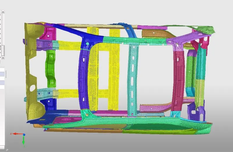
- The COG is then viewed by clicking on the show COG option in the MASS deck.
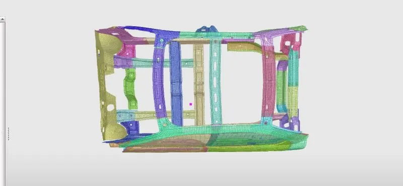
- The COG is then changed to the required position by adding the mass.
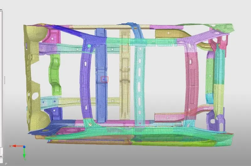
INTEFACE CREATION:
- The model is then exported from hypercrash
- The exsisting interfaces in the model are deleted as they were defined for the whole car model and not the reduced model in particular.
- A new type 7 self contact interface with friction as 0.1 is created with recommended properties.
- After the interface has been created a penetration test is done by going to the TOOLS>PENETRATION CHECK.
- After sucessfull penetration test we can move to the next step.
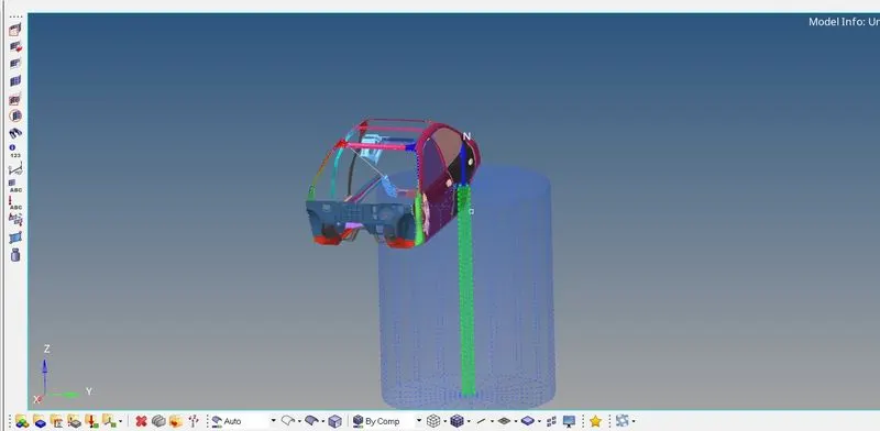
RIGID WALL CREATION:
- A temproary node is first created on the center of the both the door and then translated with 20mm.
- The new position of the node is noted.
- The rigid wall is created by going to the Solver deck right clicking CREATE>RWALL>CYL
- The XM,YM and ZM are created wiuth the co ordinated of the new treanslated node.
- The normal is then defined in the axis of Z as 0,0,1.
- The Dsearch is set as 1000 and fric is set as 0.1.
- The Diameter is set according to the FMVSS standard of side pole crash analysis.
- The diameter is set as 254mm.
INITIAL VELOCITY:
- The initial velocity for the model is created by going to the Solver deck and right clicking CREATE>BOUNDARY CONDITIONS>INIVEL .
- For the Inivel a grnd_id is to be created it can be done by right clicking on solver deck CREATE>GRNOD>GRNOD.
- The elements to be selected in the elements section. All the elements are selected in our case to apply the initial velocity.
- In the INIVEL card the grnod_id is set and the velocity components are entered.
- A initial velocity of 35mph is writen as 15.65mm/ms in the velocity components in the axis of the crash.
- It is defined in Y axis in our model.
TIME STEP:
- The required time step are edited in the MODEL deck in the cards section.
- To change the timestep to 0.5microseconds the eng_anim_dt card is opened and the Tfreq value is changed to 5.
- To change the run time of the simulation the end_run card is opened and the Tstop value is changed to 80.
OUTPUT REQUEST:
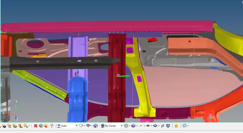
- A sectional force can be created by going to solver deck and right clicking CREATE>SECT>SECT.
- A frame of reference needs to be created at the node first. It can be created by right clicking on solver CREATE>FRAME>MOV.
- The orgin is defined as the node in the center of the cross member and the z axis node is defined as the direction in which the model would move and the third node is defined as xz plane.
- After the frame is defined the section can be created by placing the N1 node at the orgin and selecting the frame of reference that was created for the particular node.
- A grshell id is created with a strip of elements from the particular crossection.
- This can be done for the other crossmember as well.
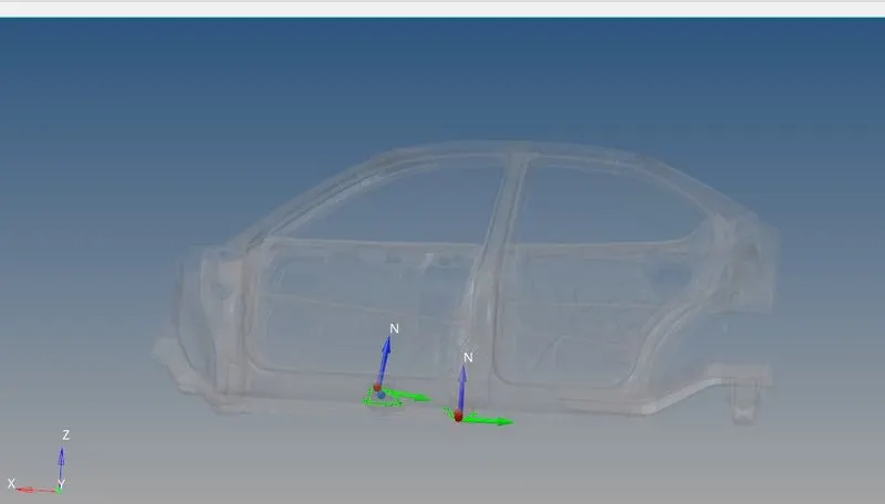
INTRUSION ON B PILLAR, HINGE PILLAR AND FUEL TANK REGION:
- To check the intrusions on the B pillar,hinge pillar and fuel tank region a spring was created from the given points.
- A property is created for the springs with card image as P4_spring.
- A very small stiffness value of 0.001 was assigned and mass of 0.1.
- The property is the assigned to the spring by going to the components card in the model deck and slecting the property as the new property we created.
OUTPUT BLOCKS:
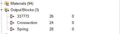
- The output blocks are required to request the output to the T01 files.
- The output can be defined by going to the model block and selecting the output card and right clicking on it and create.
- A output was requested called crossection and then crossection was selected and 2 cross members are selected.
- Another output called intrusion on springs was called and the elements was selected from the model respective for both of it.
MODEL CHECKER:
- The rad file is then imported into hypercrash and the model checker is run.
- The model checker is accessed by clicking on QUALITY>MODEL CHECKER>RUN.
- The errors are corrected and the file is then again imported back to hypermesh.
SIMULATION:
- The simulation is then started by going to TOOL>RADIOSS.
- In the options -nt 4 is enetered and the destination save folder is selected.
- The radioss button is then clicked and the simulation starts running.
SIMULATION DETAILS AND RESULT:
SIMULATION DETAILS:
ELAPSED TIME = 2847.98 s (0:47:27)
NORMAL TERMINATION
TOTAL NUMBER OF CYCLES : 80001
MASS ENERGY: 0.9070E-02 - 0.1001E-01
ENERGY ERROR : -1.5%
RESULTS:
VON MISES STRESS:
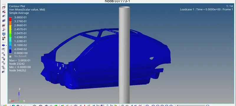
- The maximum Von Mises stress is observed as 3.685e-1 GPA.
- The h3d files after importing into hyperview the animation can be observed.
- The deformation is correct and occurs naturaly as it would in real life.
ENERGY GRAPH:
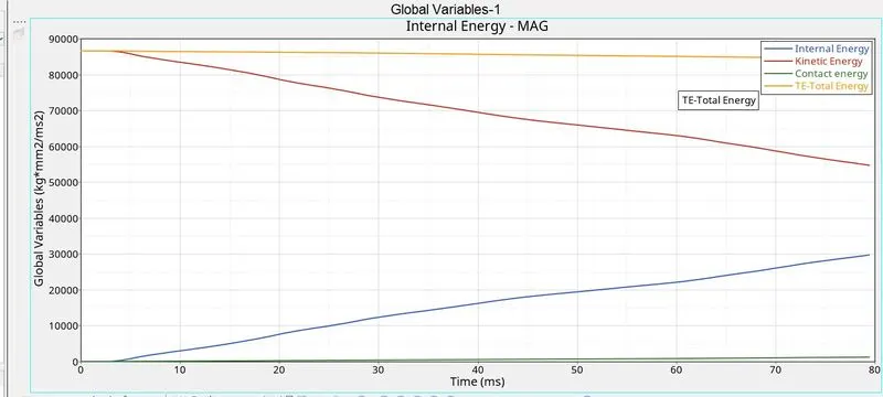
- From the above graph it is observed that the TOTAL ENERGY of the model is constant throughout.
- The kinetic energy decreases as the internal energy of the system increases.
- The kinetic energy is transfered into internal energy of the system and it keeps increasing as the deformation takes place.
- The contact energy is also constant and has a low value. This means there was very less energy needed to remove penetrations from the system.
INTRUSION ON HINGE PILLAR:
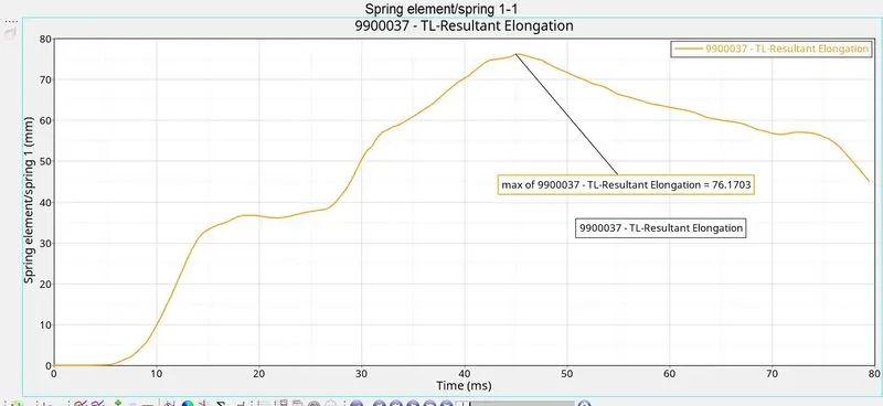
- The intrusion on the hinge pillar is 76.17mm.
- The hinge pillar is closest to the driver area.
INTRSUION ON B PILLAR:
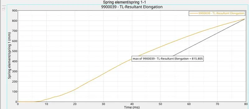
- The intrusion on B pillar is 815mm
INTRUSION ON FUEL TANK REGION:
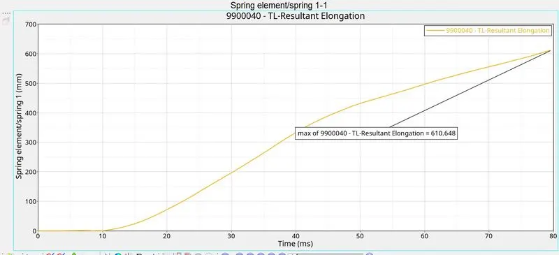
- The intrusion on the fuel region is 610.64mm.
SECTIONAL FORCE IN CROSS MEMBER 1:
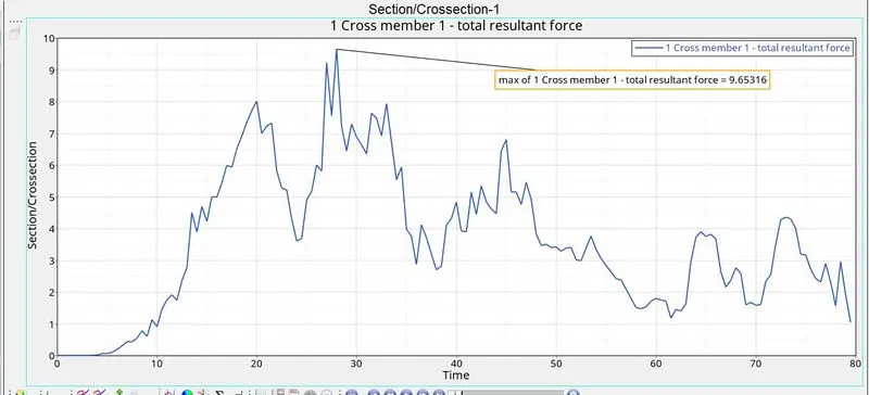
- The highest crossectional force is 9.65KN.
SECTIONAl FORCE IN CROSS MEMBER 2:
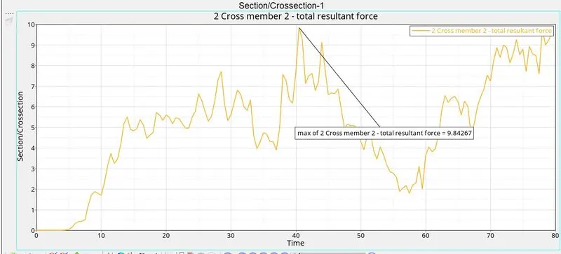
- The highest force in cross member 2 is recorded as 9.84KN.
PEAK VELOCITY OF INNER NODE IN THE DOOR:
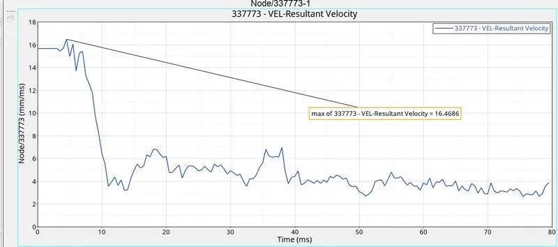
- The highest velocity recorded on the node on the inner side of the door is 16.46mm/ms.
CONCLUSION:
- There is mass addition in the model, mass has been added to correct the timestep.
- The deformation was natural
- The forces obtained seem to be resonable for the side crash.
- The intrusions are high in the B PILLAR region.