Assignment 5-RADIOSS Interfaces & Study of Effect of Notches Challenge
ASSIGNMENT - 6
RADIOSS Interfaces & Study of Effect of Notches Challenge
OBJECTIVE:
1. To learn about types of contacts and interfaces.
2. To know about how the recommended values affect the simulation.
3. To mesh the model using hypermesh.
4. To undertand the reason between the difference in each cases with respect energy graphs and forces.
MESHING:
- The given bumper model is imported into hypermesh.
- The bumper model is checked for any possible geometry errors
- The BumperBeam_mid component is not connected to the bumperbeam_front and rear part as shown in fig 1.1
- The extend option is used to correct this issue.
- The crash box panels are then toggled using toggle edge feature.
- Automesh is performed with target size as 6mm.
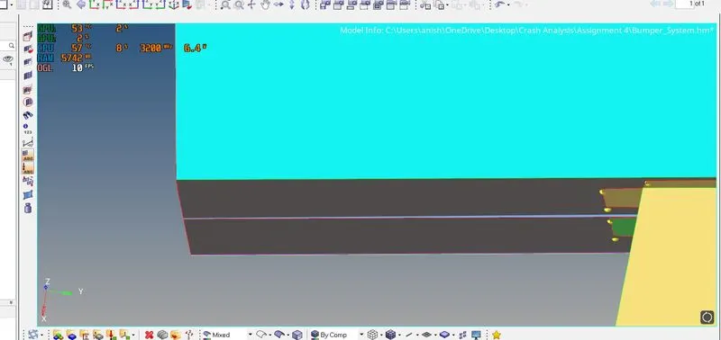
Fig 1.1
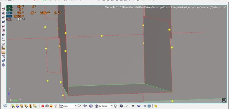
Before toggle edit
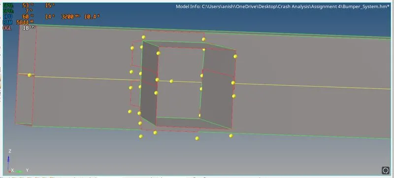
After toggle edit
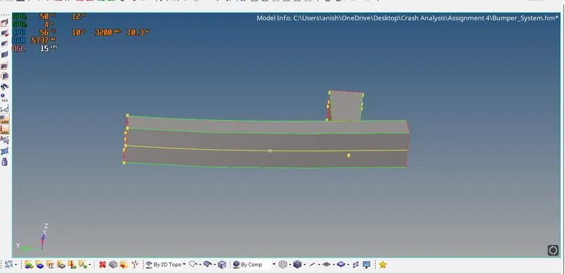
After geometry cleanup(ready to mesh)
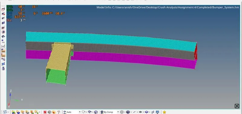
After meshing
SIMULATION AND ANALYSIS:
CASE-1:
Case Setup and Execution
- The Crash_tube_0000.rad model is imported into hypermesh.
- The interfaces defined in the model are TYPE 2 and TYPE 7
- It is noted that in TYPE 7 card the inacti=0 which is not recommended property for TYPE 7
- To create TH/PART navigate to solver browser and click on TH and then right click on TH and go to CREATE -> INTER. In entity ID select the groups (seam weld and self contact)
- The simulation is run by going into Analysis -> Radioss-> Save as (specify the folder to save simulation files) -> options -> enter nt -4 (to use 4 threads for processing) -> Radioss.
- After the simulation is complete the energy error and mass error are noted by going into the specified save folder of the simulation files.
- After the energy error and mass error are satisfied the animation files are imported into the hyperview client.
- The hyperviewe client can be accessed from the client selector.
- The .h3d file is imported from the specified folder that was used to save the simulation files.
- The von mises contour is then applied and the stress values are noted.
- The hypergraph2D client is selected from the client selecter.The T01 file is imported from simulation files folder specified for the simulation.
- Various energies and forces are plotted in the hypergraph2D.
SIMULATION DETAILS:
ELAPSED TIME: 81.18 s
NUMBER OF CYCLES: 83469
ENERGY ERROR: -3.8%
MASS ERROR: 0.00
RESULTS:
Von mises stress
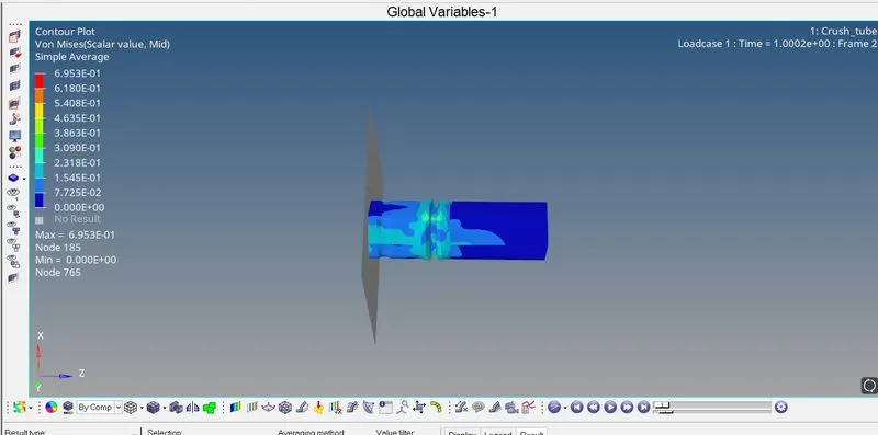
The maximum von mises stress is 6.953e-1 KN/mm2. The deformation starts taking place at the middle notch first and then the front part of the crash tube undergoes complete deformation and then the whole tube is deformed.
INTERNAL ENERGY:
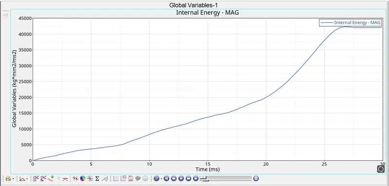
The internal energy keeps increasing as the defromation takes place. When the whole tube is defromed the energy is at its maximum.
CONTACT ENERGY
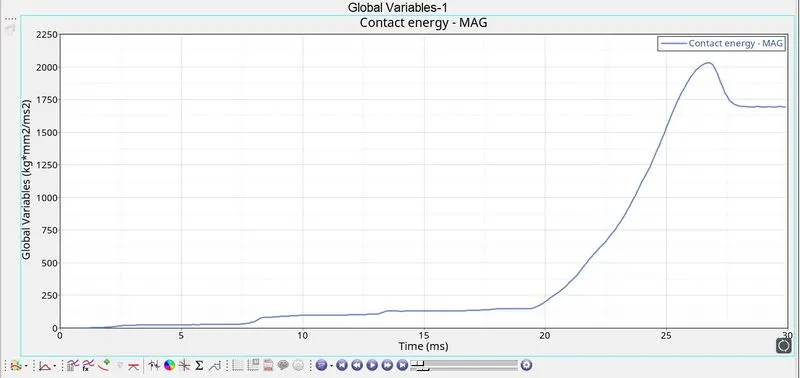
The contact energy does not go beyond 250 untill the 20ms and then surges after the 20ms mark rapidly.
RWALL FORCES
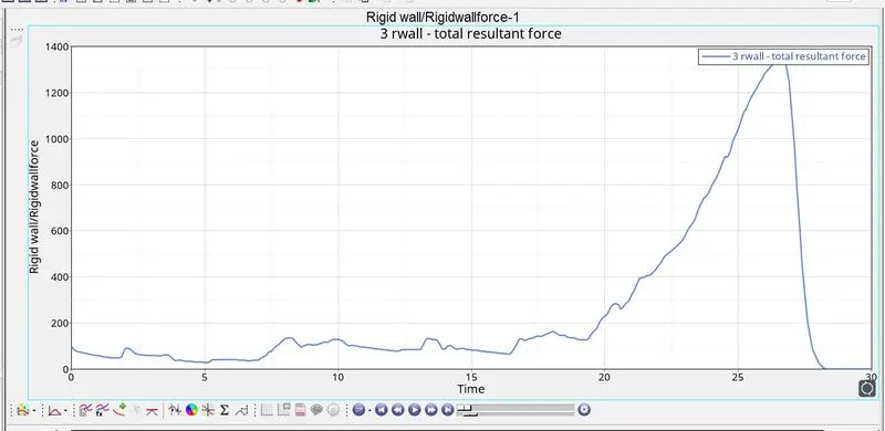
The rwall forces are fluctuating within 200 and then surge immediately after the 20ms mark that is they surge after the elements have deformed completely.
CASE-2
Case Setup and Execution
- The inact value is the assigned to the TYPE 7 card inacti=6
- To create TH/PART navigate to solver browser and click on TH and then right click on TH and go to CREATE -> INTER. In entity ID select the groups (seam weld and self contact)
- The simulation is run by going into Analysis -> Radioss-> Save as (specify the folder to save simulation files) -> options -> enter nt -4 (to use 4 threads for processing) -> Radioss.
- After the simulation is complete the energy error and mass error are noted by going into the specified save folder of the simulation files.
- After the energy error and mass error are satisfied the animation files are imported into the hyperview client.
- The hyperviewe client can be accessed from the client selector.
- The .h3d file is imported from the specified folder that was used to save the simulation files.
- The von mises contour is then applied and the stress values are noted.
- The hypergraph2D client is selected from the client selecter.The T01 file is imported from simulation files folder specified for the simulation.
- Various energies and forces are plotted in the hypergraph2D.
SIMULATION DETAILS:
ELAPSED TIME: 90.35 s
NUMBER OF CYCLES: 83469
ENERGY ERROR: -3.8%
MASS ERROR: 0.00
RESULT:
Von mises stress
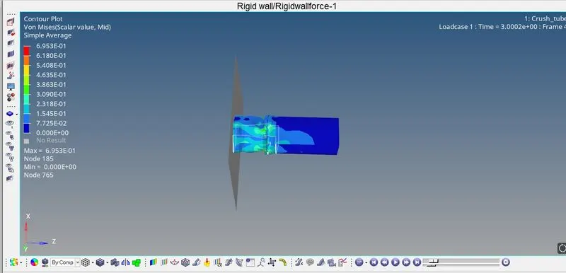
The maximum Von mises stress is6.953e-1 KN/mm2. The tube is first deformed at the middle notch region and then the upper region of the tube and then the whole tube is deformed.
INTERNAL ENERGY
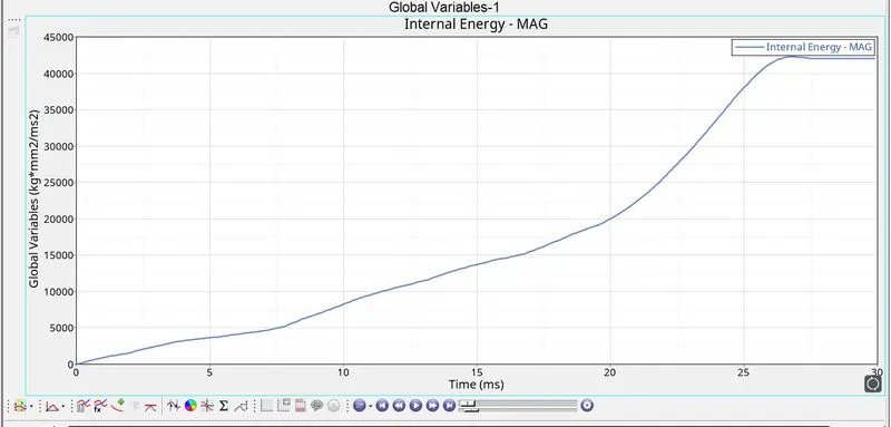
The internal energy is increasing as the tube is subjected to defromations. The internal energy is high when the deformations are completed. There is not much difference between the previous case.
CONTACT ENERGY
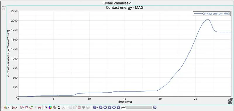
The contact energy is well within 250 and then surges after 20ms rapidly. The contact energy increases when the deformations are completed. There is not much differenece between the previous case.
RWALL FORCES
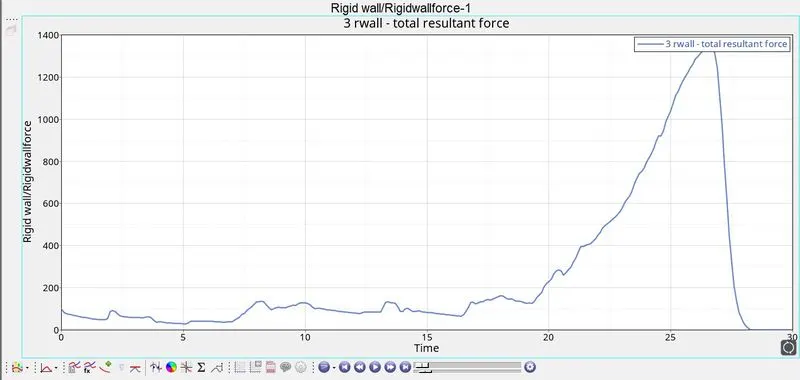
The Rwall forces are fuctuating within 200 and then climb rapildy after 20ms. There is not much difference between the previous case.
CASE-3
Case Setup and Execuion
1. The TYPE 11 contact is then created under groups in the model browser. Right click on groups adn click on create. The card image is then changed to TYPE 11 and the slave and master nodes are selected as all the components
2. To create TH/PART navigate to solver browser and click on TH and then right click on TH and go to CREATE -> INTER. In entity ID select the groups (seam weld and self contact)
3. The simulation is run by going into Analysis -> Radioss-> Save as (specify the folder to save simulation files) -> options -> enter nt -4 (to use 4 threads for processing) -> Radioss.
4. After the simulation is complete the energy error and mass error are noted by going into the specified save folder of the simulation files.
5. After the energy error and mass error are satisfied the animation files are imported into the hyperview client.
6. The hyperviewe client can be accessed from the client selector.
7. The .h3d file is imported from the specified folder that was used to save the simulation files.
8. The von mises contour is then applied and the stress values are noted.
9. The hypergraph2D client is selected from the client selecter.The T01 file is imported from simulation files folder specified for the simulation.
10. Various energies and forces are plotted in the hypergraph2D.
4. To create TH/PART navigate to solver browser and click on TH and then right click on TH and go to CREATE -> INTER. In entity ID select the groups (seam weld and self contact)
5. The simulation is run by going into Analysis -> Radioss-> Save as (specify the folder to save simulation files) -> options -> enter nt -4 (to use 4 threads for processing) -> Radioss.
6. After the simulation is complete the energy error and mass error are noted by going into the specified save folder of the simulation files.
7. After the energy error and mass error are satisfied the animation files are imported into the hyperview client.
8. The hyperviewe client can be accessed from the client selector.
9. The .h3d file is imported from the specified folder that was used to save the simulation files.
10. The von mises contour is then applied and the stress values are noted.
11. The hypergraph2D client is selected from the client selecter.The T01 file is imported from simulation files folder specified for the simulation.
12. Various energies and forces are plotted in the hypergraph2D.
RESULTS:
VON MISES
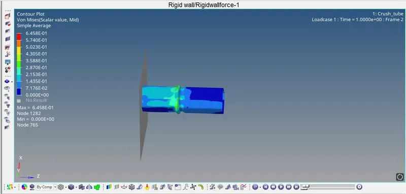
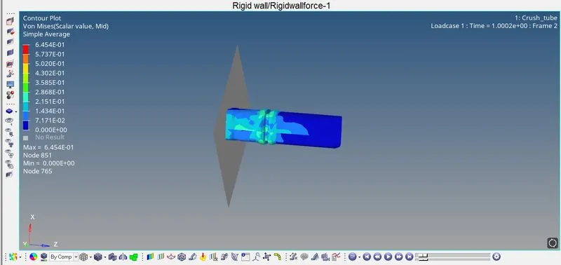
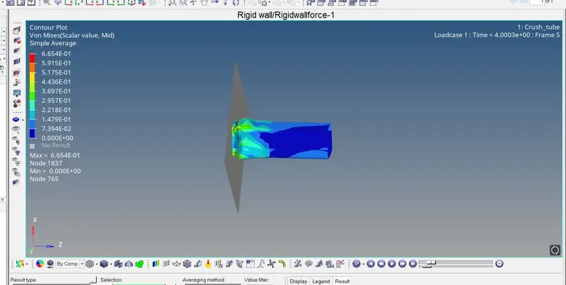
The maximum von mises stress is 6.458e-1 KN/mm2. The tube is first deformed in the center where there is a notch and then followed by the front portion and then the whole tube is deformed.
INTERNAL ENERGY
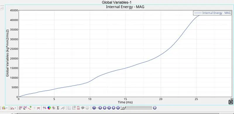
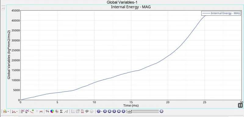
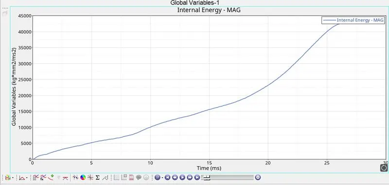
The internal energy keeps increasing as the deformation takes place. The energy is similar to that of the previous case.
CONTACT ENERGY
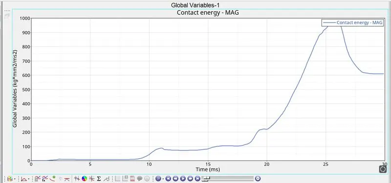
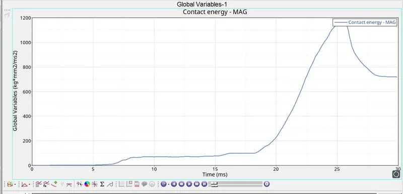
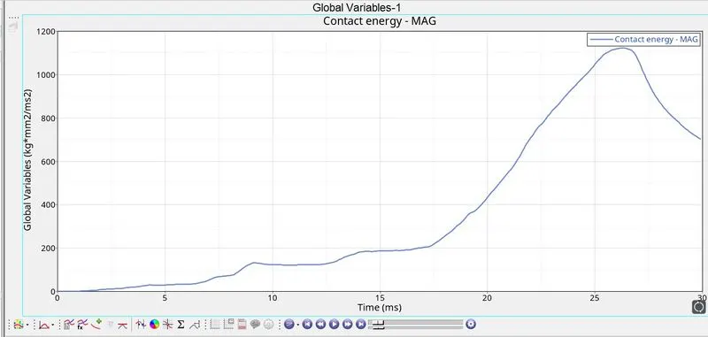
The contact energy keeps increasing after 20ms. The energy is within 200 untill then. There is not much difference between the previous case.
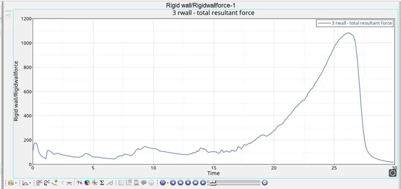
RWALL FORCES
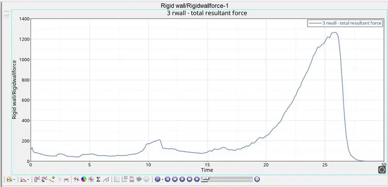
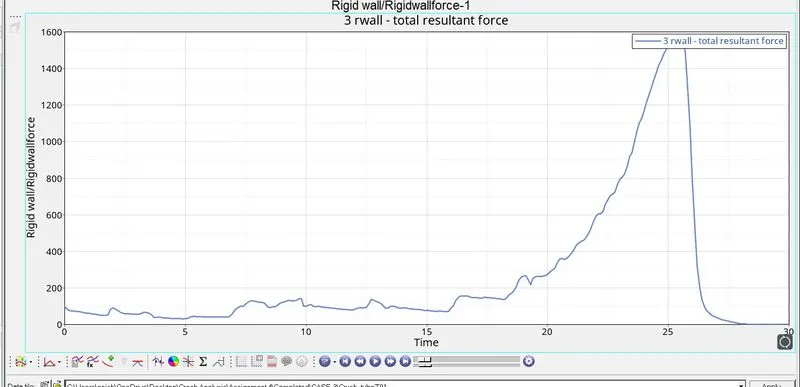
The rwall forces keep increasing.
CASE-6
Case Setup and Execute
1. The mid notches are then converted into notches on only two opposing faces. It is done by using translate and node allign option.
2. To create TH/PART navigate to solver browser and click on TH and then right click on TH and go to CREATE -> INTER. In entity ID select the groups (seam weld and self contact)
3. The simulation is run by going into Analysis -> Radioss-> Save as (specify the folder to save simulation files) -> options -> enter nt -4 (to use 4 threads for processing) -> Radioss.
4. After the simulation is complete the energy error and mass error are noted by going into the specified save folder of the simulation files.
5. After the energy error and mass error are satisfied the animation files are imported into the hyperview client.
6. The hyperviewe client can be accessed from the client selector.
7. The .h3d file is imported from the specified folder that was used to save the simulation files.
8. The von mises contour is then applied and the stress values are noted.
9. The hypergraph2D client is selected from the client selecter.The T01 file is imported from simulation files folder specified for the simulation.
10. Various energies and forces are plotted in the hypergraph2D.
RESULTS:
VON MISES
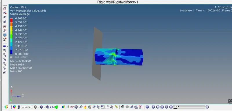
The maximum von mises stress is 6.365e-1 KN/mm2. The tube deforms in the center where the notch is present and then the front portion defroms and then the whole tube deforms.
INTERNAL ENERGY
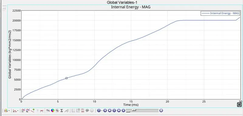
The intenral energy is lincreasing as the deformation takes place. The energy is lower compared to the other two cases. This is because of the two opposing notches on the faces.
CONTACT ENERGY
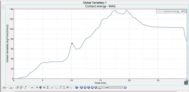
The contact energy keeps increasing as the deformation takes place. The energy is lower compared to the previous case.
RWALL FORCES
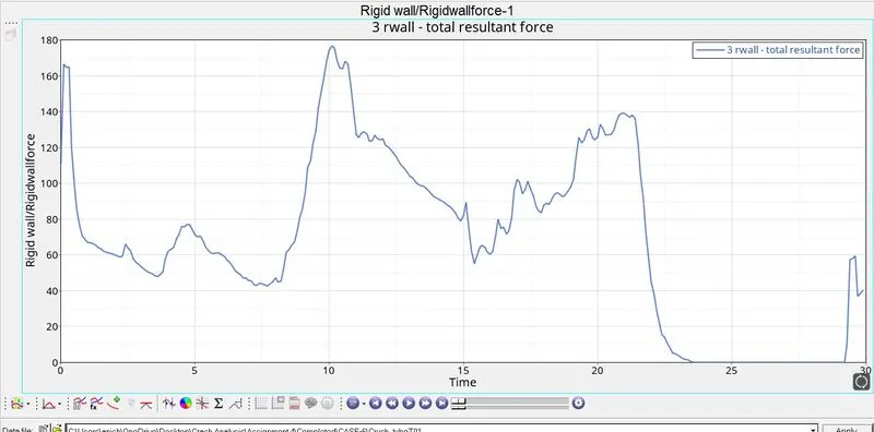
The rwall forces are fluctuating and are lower compared to the previous cases. This is because of the notches on the two opposing faces.
COMPARISON OF CASES 1,2, and 3:
|
CASES |
INTERFACES |
MAX INTERNAL ENERGY |
MAX CONTACT ENERGY |
MAX RWALL FORCES |
|
CASE 1 |
TYPE 2,7 with inacti=0 |
42500 |
2000 |
1400 |
|
CASE 2 |
TYPE 2,7 with inacti=6 |
42500 |
2000 |
1300 |
|
CASE 3 |
TYPE2,7,11 |
42600 |
1200 |
1600 |
Upon comparing the interfaces it is noted that combination of type 7 and type 11 give better results as it is a combination of Nodes to surfacces and nodes to edges.
COMPARISON OF CASE 4,5 and 6:
|
CASES |
NOTCHES |
MAX INTERNAL ENERGY |
MAX CONTACT ENERGY |
MAX RWALL FORCES |
|
CASE 4 |
No Notch |
42500 |
1100 |
1050 |
|
CASE 5 |
Notch in the Middle |
42500 |
1600 |
1250 |
|
CASE 6 |
Notch on opposing two faces |
20000 |
140 |
180 |
The case 6 where there are notches only on the two opposing faces give better results than the other two cases.