Assignment 6-Frontal Crash Simulation Challenge
ASSIGNMENT - 6
Frontal Crash Simulation Challenge
OBJECTIVE:
- To understand how the BIW of a car absorbs energy and deforms during a crash
- To create interfaces with recommended properties and check for penetrations
- To create a rigid wall
- Mass balancing of a car to the target mass of 700kg
- Correcting the CG to the required range by mass addition
- Applying initial velocity to the model
- Correcting the timestep to required values for the run
- To use the model checker and correrct errors before simulation
CASE SETUP AND EXECUTION:
UNITS CHECK:
- The Neon_front_0000.rad file is opened with a notepad and the units are checked to keep it consistent.
- The units used are Kg mm ms.
- The file is then imported into Hypercrash
MASS BALANCING AND CG:
- Under Mass option in the toolbar mass balancing is accessed.
- Mass is added in the form of car seats to the front and back rows.
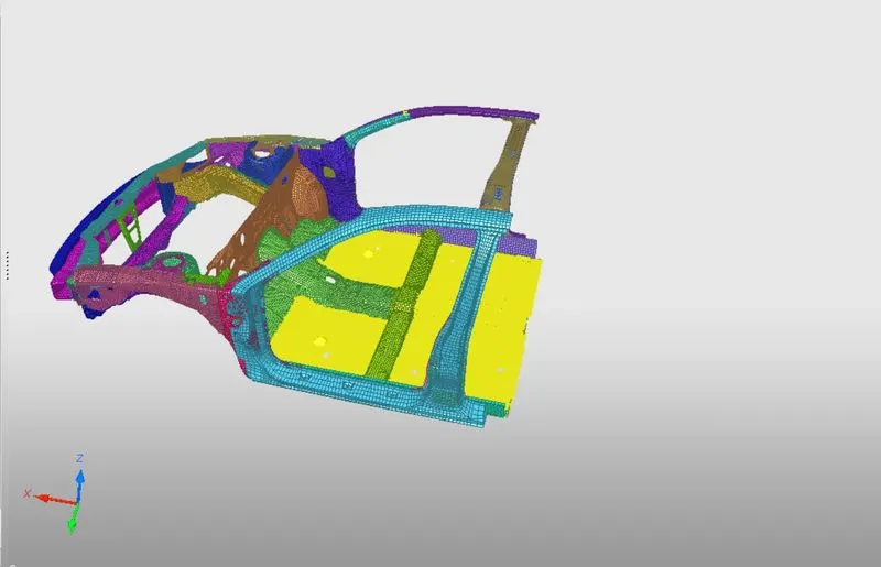
- The CG of the model is then checked by clicking on Show COG point in the mass deck.
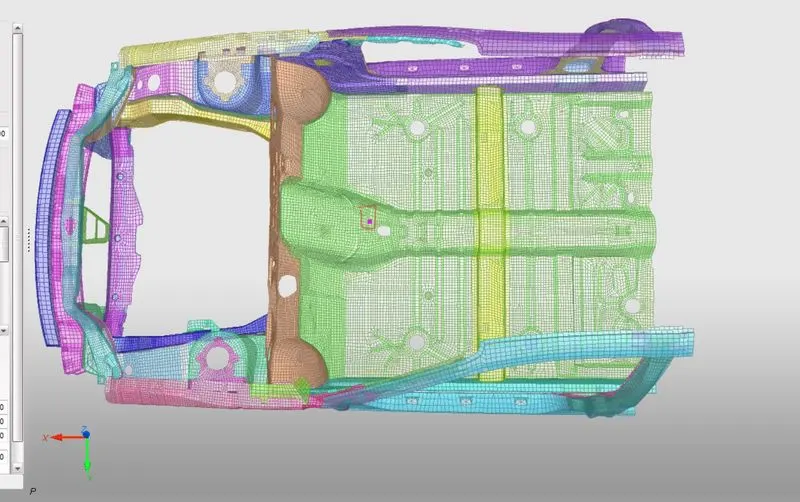
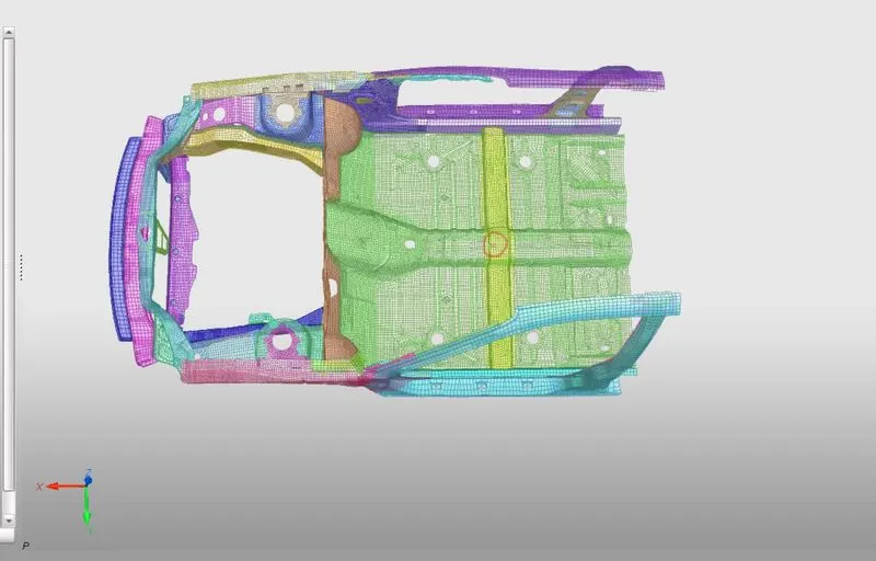
- The COG is then adjusted by the mass distribution. The COG then is moved by changing the added mass. The new COG is shown in the below figure.
INTERFACE CREATION:
- The model is then exported from hypercrash
- The exsisting interfaces in the model are deleted as they were defined for the whole car model and not the BIW in particular.
- A new type 7 self contact interface with friction as 0.2 is created with recommended properties.
- After the interface has been created a penetration test is done by going to the TOOLS>PENETRATION CHECK.
- After sucessfull penetration test we can move to the next step.
RIGID WALL CREATION:
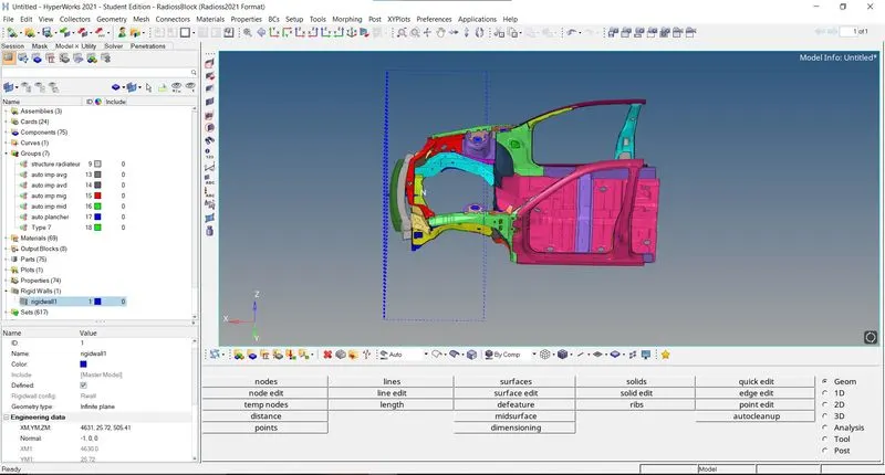
- A temproary node is first created on the center of the bumper and then translated with 20mm.
- The new position of the node is noted.
- The rigid wall is created by going to the Solver deck right clicking CREATE>RWALL>PLANE
- The XM,YM and ZM are created wiuth the co ordinated of the new treanslated node.
- The normal is then defined in the -x axis as -1,0,0.
- The Dsearch is set as 1000 and fric is set as 0.1.
INITIAL VELOCITY:
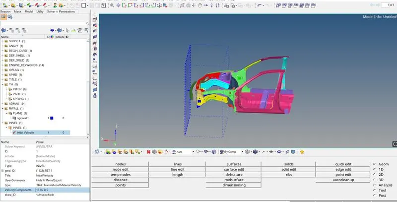
- The initial velocity for the model is created by going to the Solver deck and right clicking CREATE>BOUNDARY CONDITIONS>INIVEL .
- For the Inivel a grnd_id is to be created it can be done by right clicking on solver deck CREATE>GRNOD>GRNOD.
- The elements to be selected in the elements section. All the elements are selected in our case to apply the initial velocity.
- In the INIVEL card the grnod_id is set and the velocity components are entered.
- A initial velocity of 35mph is writen as 15.65mm/ms in the velocity components.
TIME STEP:
- The required time step are edited in the MODEL deck in the cards section.
- To change the timestep to 0.5microseconds the eng_anim_dt card is opened and the Tfreq value is changed to 5.
- To change the run time of the simulation the end_run card is opened and the Tstop value is changed to 80.
OUTPUT REQUESTS:
Sectional forces in the node 174247:
- A sectional force can be created by going to solver deck and right clicking CREATE>SECT>SECT.
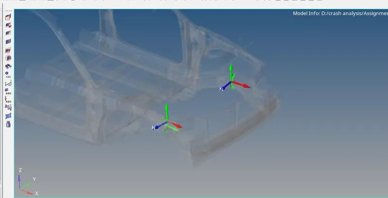
- A frame of reference needs to be created at the node first. It can be created by right clicking on solver CREATE>FRAME>MOV.
- The orgin is defined as the node 174247 and the z axis node is defined as the direction in which the model would move and the third node is defined as xz planel.
- After the frame is defined the section can be created by placing the N1 node at the orgin and selecting the frame of reference that was created for the particular node.
- A grshell id is created with a strip of elements from the particular crossection.
- This can be done on the other side of the model as well.
Axial forces from the bumper to the rails:
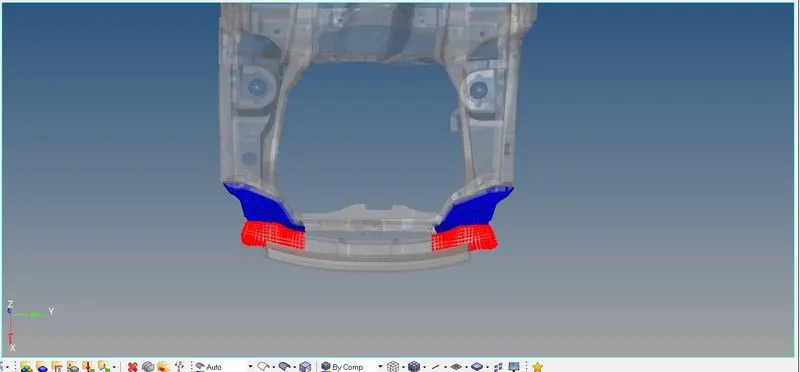
- The axial forces for the rails can be defined by creating a interface between the between the bumpers and the rails
- A type 7 contact is created and the slave nodes are selected as the bumper and the master components are selected as the rail.
- The recommended properties are used.
Shotgun crossectional force:
- The shotgun crossection can be created with the node id 139663.
- A frame of reference is created with the node id as orgin and the z axis is defined as the direction in which the model would move and the third node is defined as the yz plane.
- The section is then created and the grnode id is assigned just like the previous crossection.
- The shotgun crossection are created on both sides of the model.
A Pillar and B Pillar Crossection:
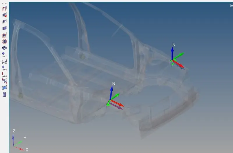
- The A pillar crossection node id 103274 is used to create the crossection on A pillar.
- A frame of reference is created by using the node id as orgin and the 2nd node z axis is defined as the direction in which the model is moving and the 3rd node is defined as the yz plane.
- A crossection is created in the similar way as the other crossection and the grnode is selected as a strip of elements from the orgin.
- Similarly the B pillar is also created in both the sides.
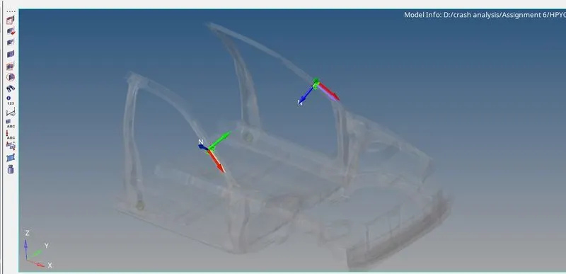
Acceleration curve recieved on the accelerometer:
- A accelerometer is to be created on the base of the Pillar B ( B pillar rocker).
- An accelerometer can be created by right clicking on the solver deck and CREATE>ACCEL.
- Select the node id on the B pillar rcoker.
- Then assign it to the sensor by right clicking on CREATE>SENSOR>ACCE
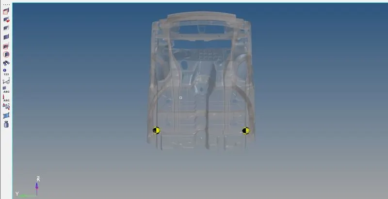
Intrusions on the dash wall (66695,66244):
- To check the intrusions on the dash wall a spring was created from the given nodes by using the node id.
- A proprty is created for the springs with card image as P4_spring.
- A very small stiffness value of 0.001 was assigned and mass of 0.1.
- The property is the assigned to the spring by going to the components card in the model deck and slecting the property as the new property we created.
OUTPUT BLOCKS:
- The output blocks are required to request the output to the T01 files.
- The output can be defined by going to the model block and selecting the output card and right clicking on it and create.
- A output was requested called crossection and then crossection was selected and 6 crossection are selected.
- Another ouptut was called accelerometer and the acceleration was selected and the created accelerometer was added into it.
- Another output called intrusion on springs was called and the element was selected from the model respectivel for both of it.
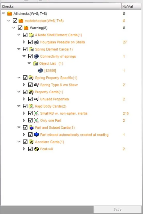
MODEL CHECKER:
- The rad file is then imported into hypercrash and the model checker is run.
- The model checker is accessed by clicking on QUALITY>MODEL CHECKER>RUN.
- The errors are corrected and the file is then again imported back to hypermesh.
SIMULATION:
- The simulation is then started by going to TOOL>RADIOSS.
- In the options -nt 4 is enetered and the destination save folder is selected.
- The radioss button is then clicked and the simulation starts running.
SIMULATION DETAILS:
ELAPSED TIME = 2099.60 s (0:34:59)
NORMAL TERMINATION
TOTAL NUMBER OF CYCLES : 80001
MASS ENERGY:
- The mass energy upon the simulation start was at 0.1397E-1.
- The mass energy upon the simulation end was at 0.2889E-1.
ENERGY ERROR:
- The energy error is at -1.3%
RESULT:
Von Mises stress:
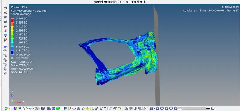
- The maximum Von Mises stress observed is 3.88e-1 GPA.
- On observing the h3d file after importing it into hyperview we can see how the model deforms.
- The model deforms as how it was supposed to defrom naturally.
ENERGY GRAPH:
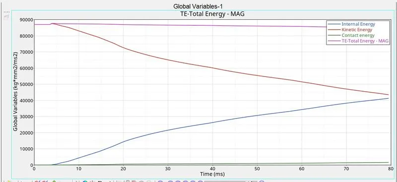
- The total energy of the model is at a constant through out the simulation.
- The kinetic energy decreases and the internal energy of the system increases.
- The contact energy is also low and that means there were less forces required to remove penetration in the system.
- The increasing contact energy means the parts were deforming.
CROSSECTIONAL FORCES ON THE RAIL:
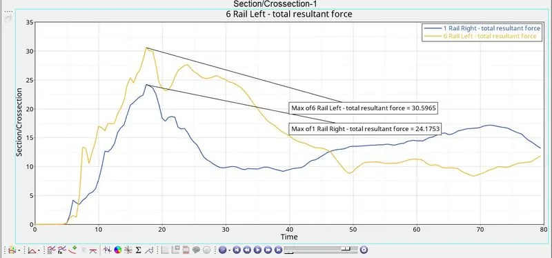
- The maximum force recorded on Rail left is 30kn
- The maximum force recorded on Rail right is 24kn
- It is noted from the h3d file that the left rail has deformed more than the right rail and hence the forces are not euqual and hence the left rail force is higher than the right rail force.
- It also means that the Rail left has absorbed more energy than the Right rail
SHOTGUN CROSSECTIONAL FORCES:
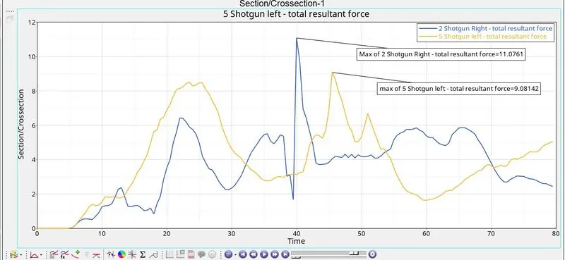
- The maximum value obtained is on shotgun right. The maximum value on shotgun right is 11.07Kn.
- The maximum value on shotgun left is 9.08Kn.
A PILLAR CROSSECTIONAL FORCES:
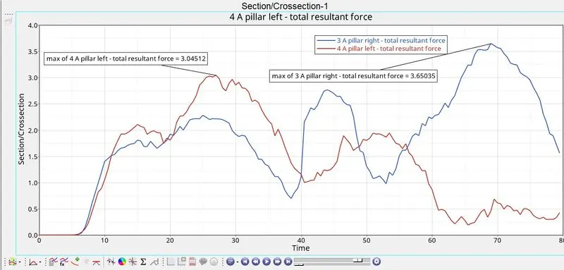
- The maximum force on A pillar left is 3.04KN.
- The maximum force on A pillar right is 3.65KN.
- The force in both the pillar has been reduced considerably because the components in front of it have absorbed the enegy from the rigid wall and deformed hence less forces are transmitted into the A pillar of the car.
ACCELERATION FORCES:
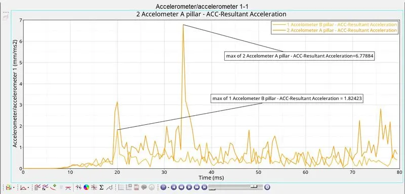
- Max acceleration on A pillar during the crash is 6.7784mm/ms on converting it to Mph it is around 15.21Mph.
- Max acceleration on B pillar during the crash is 1.8243mm/mson converting it to Mph it is around 4.03Mph
- The accelerometer was fixed on the end of A pillar to monitor the acceleration upon impact and it seen that after impact the acceleration has reduced considerably upon impact.
INTRUSIONS ON THE DASH WALL:
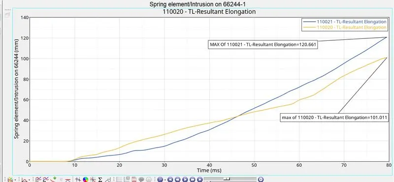
- The max intrusion the node 66695 of the dash wall is 101.11mm.
- The max intrusion on the node 66244 of the dash wall is 120.661mm.
- The intrusion springs were defined in such a way so that we could see how much the dash wall has moved towards the passenger seats.
- The intrusion on the node relate how much the dashwall affects the pedals.
AXIAL FORCE RECIVED ON THE BUMPER FROM THE RAIL:
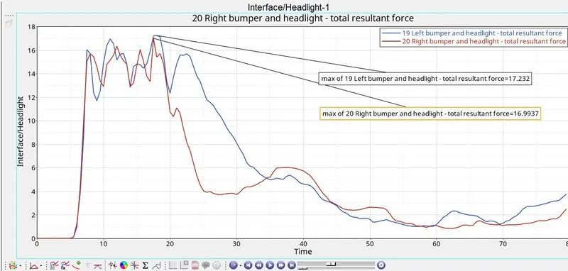
- The max force on the left bumper and rail is 17.32KN.
- The max force on the right bumper and the rail is 16.9937KN.
- The energy climbs up rapidly as it was the first point of contact in the car model and it falls down anfter the deformation is complete.
CONCLUSION:
- The car deformed natrually and the forces were recorded
- Mass was added into the system in order to make the current time step larger than the critical time step.
- The negative energy error in the system says that energy has dissipitated from the system.