Assignment 7-Side Pole Crash Simulation Challenge
OBJECTIVE:
- Check unit system and either follow [Mg mm s] or [Kg mm ms].
- Create appropriate interface ,friction 0.2 and recommended parameters.
- Make sure of no penetration and intersections.
- Create rigid wall with friction 0.1 as per referance model.
- Compare the model weight with the referance model and use added masses to reach target weight 700kg while getting CG about the required range.
- Initial velocity as shown in picture.
- Use model checker to ensure good quality.
- Timestep :0.5 to 0.1 microseconds.
- Run 80ms.
Output requests:
- Sectional force in the cross member.
- Intrusion at B pillar,hinge pillar and fuel tank region.Provide recommendation on what can help to reduce Fuel tank intrusion.
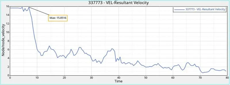
- Peak velocity of inner node of the door.
CASE SETUP:
First we will import the solver deck file neon_front_0000.rad in Radioss using Import Solver Deck option.
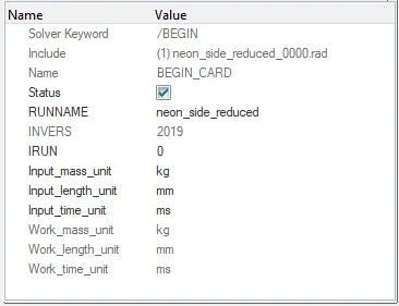
Check the unit system in BEGIN_CARD,here in this model the unit system is [kg mm ms].
Penetration Check:
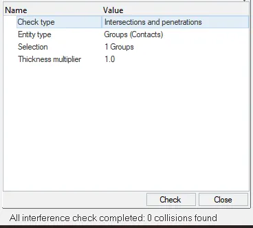
Now we will check for penetration by using 'check penetrations' options in the Tools menu.
Interface:
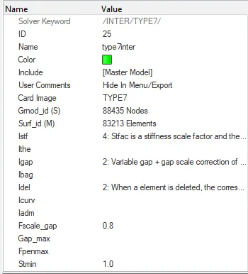
Now we will create interface 'interface' for this model, we will create Type 7 interface for all the components of the model as it is self-impacting.
We will go to Solver browser and we delete all the pre-exiting group of interface.
We create a new interface by selecting all the nodes all components for Slave nodes (Grnod_id) and master nodes (Surf_id). Then we will define all the
recommended parameters for Type 7 interface Istf = 4, Igap = 2, Idel = 2, Fscale_gap = 0.8, Stmin = 1 kN, Fric = 0.2, Gapmin = 0.5, Iform = 2.
Rigid Wall:
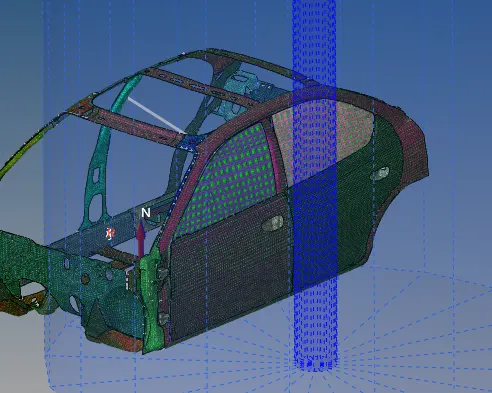
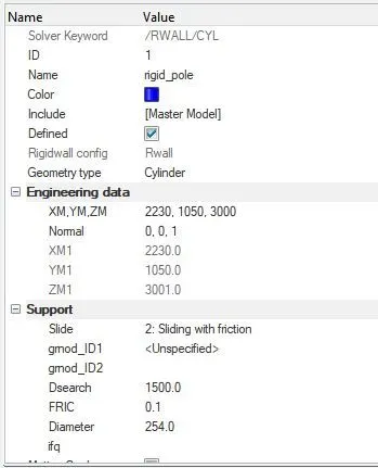
For creating rigid wall we will select the outer most node on the door and create a tempory node using 'temp node' option. Then we will right click in solver browser and go to Create > RWALL > CYL.
We will give a gap of 10 mm in X direction as the wall should not be connected to the model. Also we will give diameter of the cyclindrical rigid wall as 254 mm. Slide value as 2: Sliding with friction, Dsearch as 1500 and FRIC value as 0.1
Initial velocity:
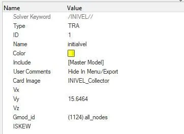
In the solver browser go to Create > BOUNDARY CONDITIONS > INIVEL.
In INIVEL card, we will select all the components for grnd_ID. We will give the initial velocity of 35 mph or 15.6464 mm/ms in X-axis and mark the the velocity TRA that is translational.
Cross-sections:
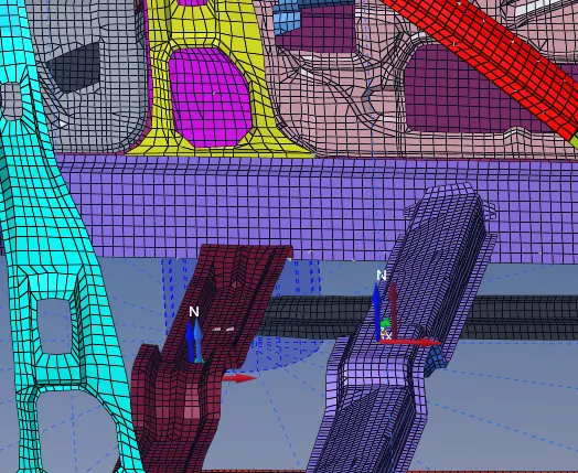
First we are going to create the moving frames on the points where cross-sectional force is asked to calculate. In order to create the frame we will go to create--> Frame--> Mov
After that create the sections so that we can check the forces on these points. To create the section we will go to the Create--> Sect--> Sect
Intrusions:
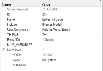
We need to find the intrusions at B-pillar, hinge pillar and fuel tank. We will create moving frames at the opposite side at right B-pillar, hinge pillar and fuel tank
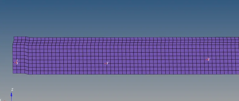
Then we will create time history for the selected nodes with respect to the respective skews.
Peak Velocity of Node:
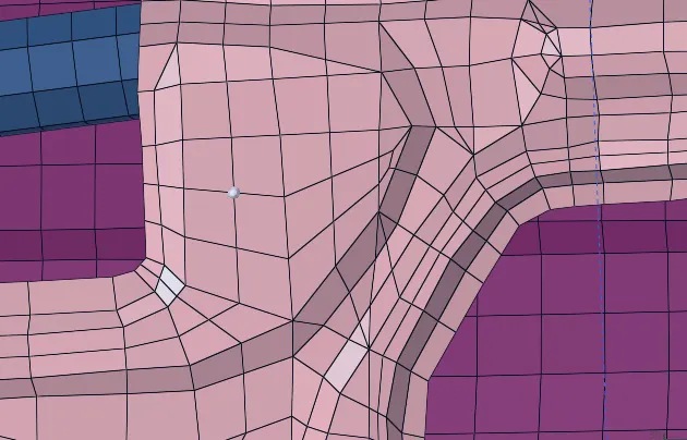
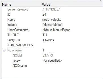
To find peak velocity at the inner node of the door, we will create a moving frame at the node location by using the same procedure as we used in cross section creation. Then we will create output block for the peak velocity by specifying the node 337773 and the frame or skew based on which the peak velocity is calculated.
Mass Balancing:
By checking the mass of existing model we can see that the mass of the vehicle is 166 kg and the CG of the vehicle is at the pink point.
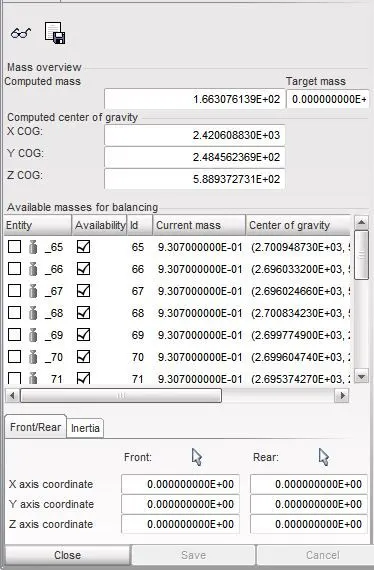
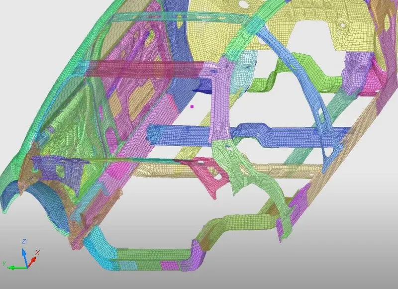
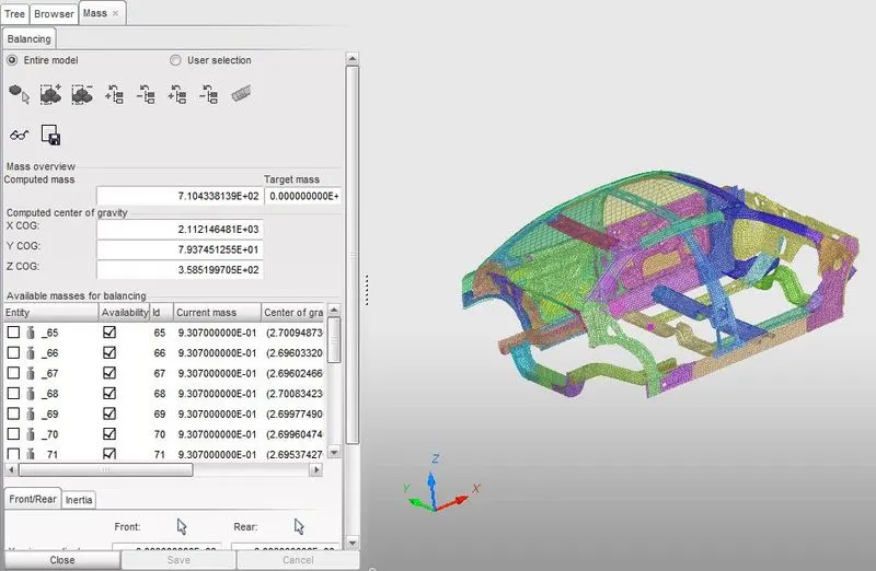
We need to increase the mass of the vehicle to 700 Kg so we need to increase the mass of the model by keeping in mind the new CG location should come somewhere just behind the front row seats.
Now we will go to the solver browser we will right click and navigate to Create > ADMAS. In ADMAS panel, we will specify the required mass to selected nodes and for Mass type, we will select Mass/node option.
So we will create different weight at different locations similarly.
Time Step and Run time:
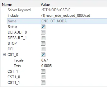
For checking time step and and run time will go to Model browser and Open ENG_RUN card and ENG_DT_NODA.
Model Checker –
To check the quality of the model,navigate to Tools > Model Checker > RadiossBlock.
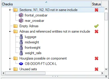
The error which says the nodes N1, N2, N3 badly defined, can be ignored as the sections are assigned to moving frames which are created separately. Other errors and warnings can also be ignored.
SIMULATION AND RESULTS :
Check Energy error and Mass error, open the engine .out file of the model and check the last column for Energy and Mass error. Our Max Energy error comes out to be -2.4% which is acceptable. Total number of cycles are 160000 and time elapsed is 9784.8 sec.
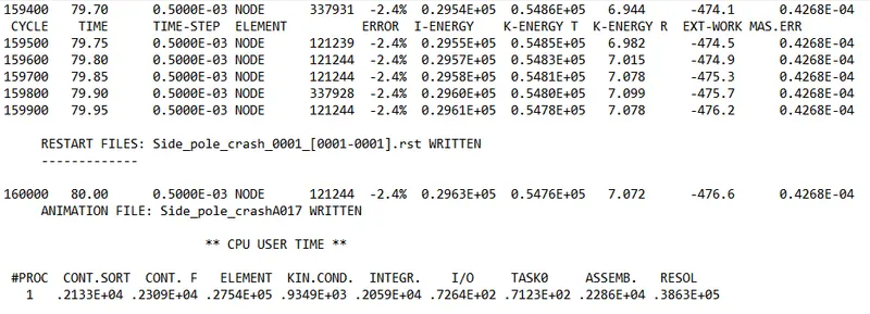
For seeing results we will got to hypergraph.
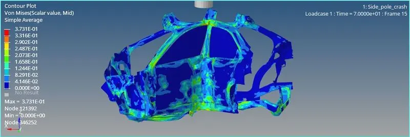
As this is reduced model we can see that the deformations are not realistic.We can see that stress concentrations are not localized,max stress is getting generated at the B-pillar as the B-pillar is taking most of the impact.
Energies:
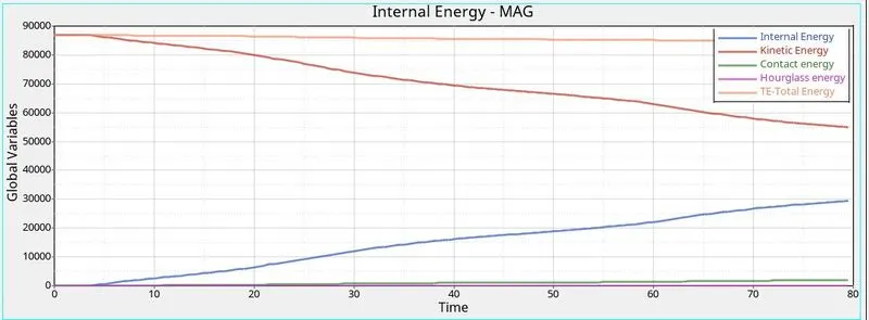
As the vehicle crashes and absorbs energy Kinetic energy starts to decrease and internal energy increaes.the energy error is very less so almost all the kinetic energy is getting converted to internal energy, moreover we have used QEPH elements so the Hourglass energy generated is almost zero, and due to contact between elements the contct energy increases slightly.
Cross-sectionaal Forces
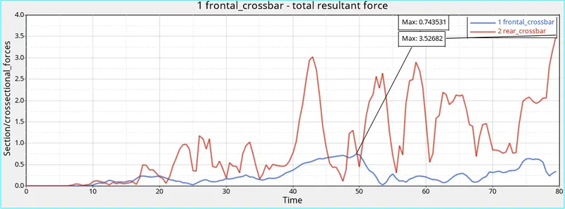
From the above plot, we can see that the total resultant force in the rear cross member is more than the front cross member. As
the rear cross member is in line with the Pole, it experiences more force.
Intrusion
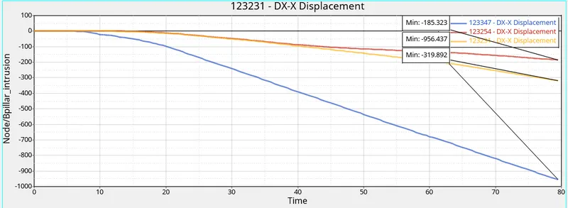
Fuel tank intrusion is about 956 mm which is not at all acceptable and to further decrese the intrusion some extra cross members are required which can absorb more energy and hence decreases the intrusions value.
B-pillar has inrusion of 319 mm and Hinge-Pillar has a intrusion value of 185 mm.
Peak Velocity:
Peak velocity of the node on the inside of the door is recorded to be 15.8516 m/sec, the node velocity rapidly decreases after the collision and decreases at a rather slow rate.
Conclusion:
As the model is reduced to limited parts, we get somewhat unrealistic deformations and results. The fuel tank experiences very high intrusions which are not acceptable.