Assignment 3-2D Element Formulation Challenge
Objective:
Use a crash beam file with runtime of 55 milisec and min/max animation freq as 25 and 60 respectively and run the simulation without any changes in the element properties.
Run a second simulation with same runtime and animation freqencies and change the element properties as mentioned in the question above.
Finally compare the results of two simulations on the basis of rigid wall forces, internal energy, hourglass energy, contact energy and total energy and comment on the changes in the result observed.
Case 1
Set the runtime to 55 miliseconds in the 0001.rad file.
Also change the maximum and minimum animation steps to 60 and 25 respectively by dividing timestep i.e. 55 miliseconds
so minimum freq. 55/25 = 0.022
max freq. 55/60 = 0.0009160
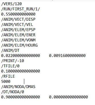
Import FIRST_RUN_0000.rad file in solver deck.
Go to analysis tab and create a saperate folder for solver files to generate in it and hit radioss.
Let the solver process run and then click on Results to see the simulation animation in Hyperview.
Check if the energy error and mass error are under the allowable limit or not by clicking the FIRST_RUN_0001.out file
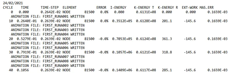
As energy error is 0 or negative it is under allowable range.
So go for ploting the required curves.
Click on Contour to see different prameters like displacement, velocities, hourglass energy on each element.
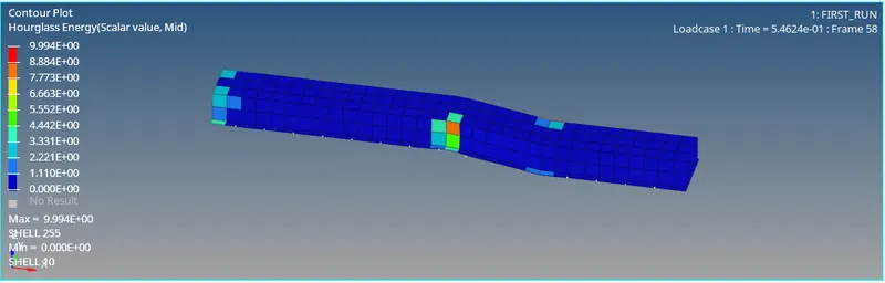
For ploting graphs you can either divide the window in 2 halfs or directly click on Hypergraph option to plot the curves for the simulations:
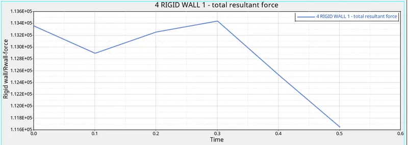
The plots obtained are attached below:
1. Rigid wall forces
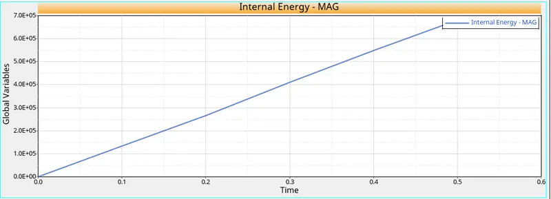
2. Internal energy
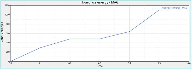
3. Hourglass energy
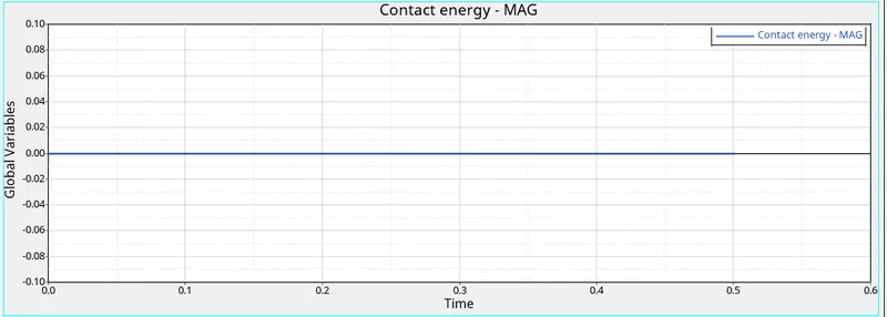
4. Contact energy
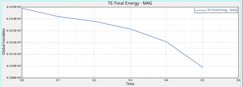
5. Total energy
Case 2
Set the runtime to 55 miliseconds in the 0001.rad file.
Also change the maximum and minimum animation steps to 60 and 25 respectively by dividing timestep i.e. 55 miliseconds
so minimum freq. 55/25 = 0.022
max freq. 55/60 = 0.0009160
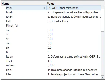
This time change the element properties as required in the question.
|
Ishell =24 |
QEPH 4 nodes shells are best combination of cost and accuracy. | |
|
Ismstr=2 |
Full geometric nonlinearities (default)with possible small strain formulation activation in RADIOSS Engine. | |
|
Ish3n=2 |
Standard 3 noded shell (C0)with modification for large rotation(default) |
|
| N=5 | Number of integration points set to 5 for accuracy bending. | |
|
Ithick=1 |
Thickness change is taken into account for accuracy. |
|
|
Iplas=1 |
Iterative plasticity for good accuracy. |
Properties changed are shown below:
After changing the propeties save it as saperate file and run the solver.
Let the solver process run and then click on Results to see the simulation animation in Hyperview.
Check if the energy error and mass error are under the allowable limit or not by clicking the FIRST_RUN_0001.out file
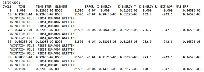
As energy error is 0 or negative it is under allowable range.
So go for ploting the required curves.
Click on Contour to see different prameters like displacement, velocities, hourglass energy on each element.
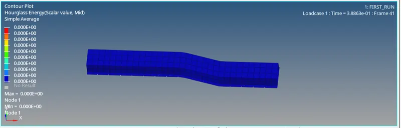
For ploting graphs you can either divide the window in 2 halfs or directly click on Hypergraph option to plot the curves for the simulations:
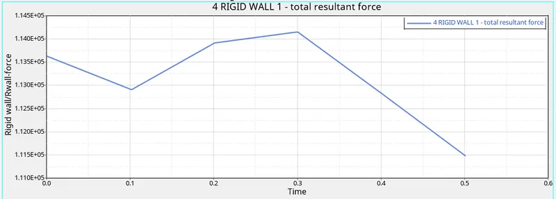
The plots obtained are attached below:
1. Rigid wall forces
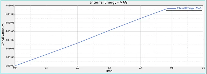
2. Internal energy
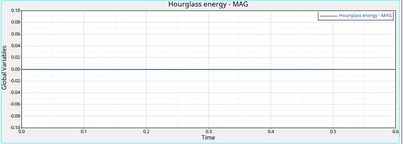
3. Hourglass energy
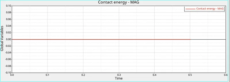
4. Contact energy
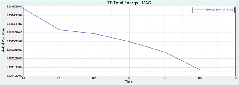
5. Total energy
The difference in both the cases can be seen from the animation itself.
In case 1 the element deformation is not very convincing as the mesh size is course and we have not defined any properties to the elements.
Also as no element type was selected, due to reduced integration there is high amount of hourglass enegy can be seen in plots.
In case 2 when properties are assgined to the elements the deformations are much more predictable and convincing and close to actual scenario.
Also as we have selected QEPH element type which has higher Ishell points the hourglass energy in the plot comes out to be almost zero.
Internal energy of the system increases and remains exactly same in both the cases, as after the impact the kinetic energy is getting absorbed by the beam component and increasing its internal energy.
Hourglass is a situation when a node or group of nodes is/are moving without registering any stress value, it happens due to reduced integration and which creates unstability in the system.
To avoid hourglass situation the we need perturbation method, perturbation can be implimented by two different methods
1. Viscous method
In this method hourglass is detected by relative motion in the nodes.
It creates a artificial damping in the system by creating a artifical force which stablizes the node deformation.
The force is defined accoring to element stiffness. The force introduces an artificial energy known as Hourglass energy.
It damps velocity and not the forces.
2. Physical Method
In this method stiffness is added at material level by changing the material properties and it has a larger effect on the component.
This method need less hourglass energy and except for very high veloity applications (100-1000 m/sec) this method works well with all other applications.