Assignment 7-Side Pole Crash Simulation Challenge
Objectives:-
Perform the side crash analysis model in the given BIW model.
ABSTRACT
Side impact collisions are a major road safety problem in most western countries,accounting for up to 35% of all severe road trauma and the problem is not
currently addressed effectively. While crash severities tend to be relatively low,the injuries sustained to occupants seated in the struck (near side) and nonstruck or far side, tend to be severe and life-threatening. The most common side impacts occur at intersections (car-car crashes) and pole or tree collisions (singlevehicles). Examples of an in-depth examination of side impacts show severe damage to the car and the occupants from these crashes. The paper offers a range of countermeasures to reduce these impacts or mitigate the severity of
occupant injuries.
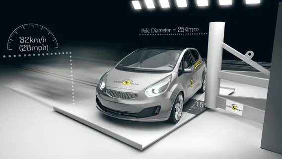
- DATA ANALYSIS
Analyses were undertaken of crash patterns in Australia and the USA to show the changing shift of crash types and recent increases in side-impact collisions.Analyses of retrospective in-depth crash databases of NASS/CDS and MIDS was carried out to show side-impact crash configurations and injury patterns in both countries. These databases comprise in-depth crash data for tow-away crashes and weighted to be and weighted to be representative of all crashes in their respective countries. A Harm analysis was also carried out to indicate the extent of trauma associated with side impacts and priorities for intervention.
Trends in Side Impacts
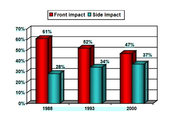
The findings in Fig 1 show that fatal side-impact crashes have increased in their number and proportion over frontal crashes in recent years in Australia. [4]. The proportion of front crashes has become less while the equivalent side-impact proportion has become larger. This probably reflects the greater success in addressing head-on crashes through frontal crash regulation followed by the introduction of seat belts and airbags to better restrain occupants from injury in these crashes. While side impact regulations have been introduced in these countries more recently, unfortunately, similar successes are not apparent in these crash types. In fact, the numbers of these collisions are at best stable or even growing in recent times [4]. Side impacts can occur to the occupant on the struck side (near side) or on the opposite side of the vehicle (far side). Past initiatives have focused almost exclusively on protecting the near side occupant as they generally experience the full force of the impact. However, 30 to 40 percent of the Harm experienced in a side-impact crash occurs to the far side occupant and research is now focussing on how best to protect the far side occupant [5].
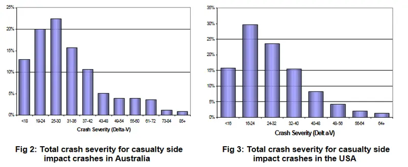
- These figures show that the median crash severity for side impacts in both countries is between 24 and 32
km/h and that on average 90 percent of these crashes occur below 48km/h impact speeds (88 percent in
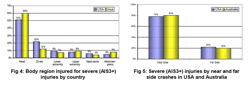
Australia and 92 percent in the USA). Side Impact Injuries Figures 4 and 5 show the proportion of body region injuries from side impacts in
the USA and Australia, as well as the proportions by seating position.
Pole Collision
This was a run-off-road crash on a rural road in eastern Victoria on a Friday afternoon in May. The case vehicle, a small hatch-back sedan, was travelling
downhill at dusk around a gentle right-hand curve when it lost control, rotating 90° before striking a tree sideways at the driver’s door. The sole occupant, a 31-
year-old female was airlifted to a Melbourne trauma hospital, where she remained for eight days. She maintained that the road was wet and she lost control on its slippery surface (witnesses also claimed it was slippery from diesel fuel from an ageing truck that had just passed by).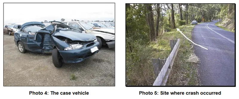
The driver suffered multiple pelvic fractures (AIS 3) from impact with the front door, a highly comminuted fracture to the left distal radius (AIS 3) and an open
dislocation of the left distal radioulnar (AIS 2) from the steering wheel, a small laceration to her spleen (AIS 2) from the seat belt, penetrating wounds to her
right thigh (AIS 1) and her left medial calf (AIS 1) from the facia, and various other lacerations and contusions. While there was some barrier protection from the trees in certain sections of the road, there was none in the particular region where she left the road and hit the trees (see Photo 5). The speed limit on that road was 100km/h. although the driver claimed to have only been travelling around 70km/h (delta-V was calculated to be 31km/h, suggesting her speed estimate was probably correct.
Aim:-
The following parameters are done in the model:-
- Check unit system and either follow[Mg mm s] or [Kg mm ms].
- Create appropriate interface ,friction 0.2 and recommended parameters.
- Make sure of no penetrations and intersection.
- Correct rigid bodies if any issues.
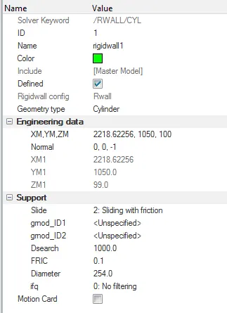
- Create rigid wall with friction 0.1.
- Compare the model weight with the full scale 300k nodes model and use added masses to reach target weight 700kg
while getting CG about the required range. - Initial velocity 35 mph.
- Use model checker to ensure good quality.
Time-step :0.5 to 0.1 microseconds. - Run 80 ms.
Check unit system:-
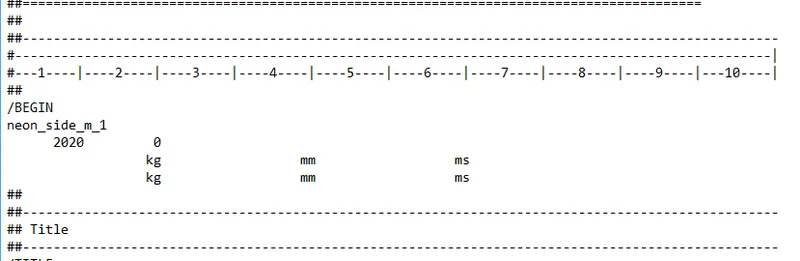
For that open the neon_front_0000.rad file in the notepad.
here, unit system is kg mm ms.
Procedure:-
Create appropriate interface ,friction 0.2 and recommended parameters.
- Here we seen that number of nodes are more than 10k, due to that we can not run the simulation in hypercrash, then we run
the simulation in hypermesh software. - First of all import neon_side_0000.rad file in hypermesh using import>import solver deck command.
- After that open interface in browser and delete all interfaces and create new type 7 interface.
- Here main recommanded parameters is:-

istf=4
igap=2
gap scale factor=0.8
idel=2
stmin=1
gapmin=0.5
inacti=6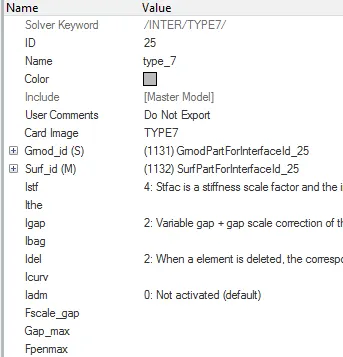
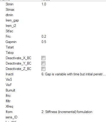
fric=0.2
iform=2
Make sure of no penetrations and intersection:-
-This check is require because of due to penetrations and intersection we doe's not receive proper output and errors are
generated.
-For the penetration check go to the tools>penetration checks.
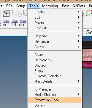
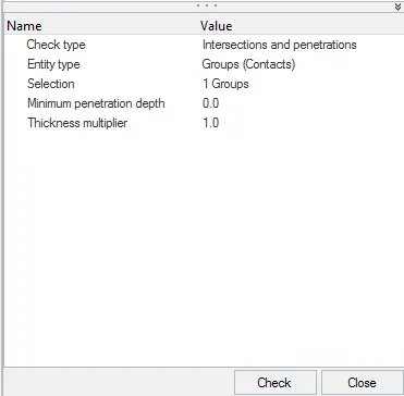
Create rigid wall with friction 0.1:-
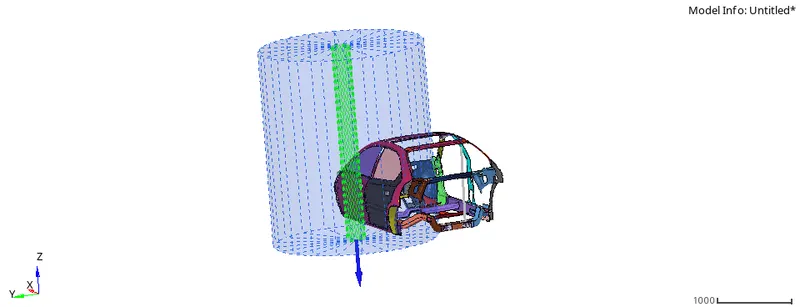
create the rigid wall at front of the vehicle.
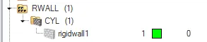
For that use this way for creationright click on solver tab & choose create>rwall>cyl
- Distance for slave search=1000
- Friction=0.1
- sliding= sliding with friction
- moving flag=Fixed
Compare the model weight with the full scale 300k nodes model and use added masses to reach target weight 700kg while
getting CG about the required range:-
-
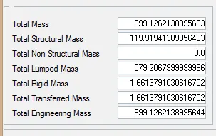
- First of all check the mass of the model.
- - For that go to the tools>mass details> mass only
- - Here we seen that mass of the model is 188.42544kg, but we required 700kg.
- - Then we add the 511.5746kg(700-188.4254) mass required.
-
- For that we use admas command.(go to solver tab and right click and select admas opction)
*
Initial velocity 35 mph:-
-
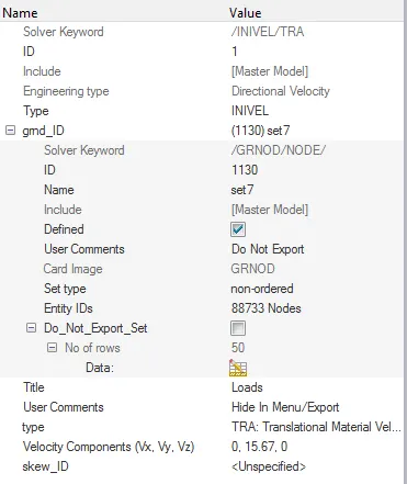
- Here, available of the value of velocity is 35 mph, but we required in to the mm/ms.(as per our unit system)(note:- mph=miles
per hour)
- - For that go to google and open the unit converter calculator,and find the value in mm/ms.
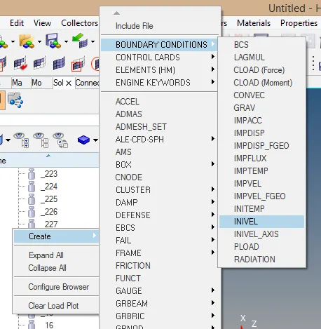
- - Now for apply the initial velocity go to the solver tab and right click and choose create>>boundary conditions>>INIVEL
-
- Here, we apply velocity on all over model. so choose fully model.
*
Use model checker to ensure good quality:-
-
- Model checker is a useful for check the model before run the simulation.
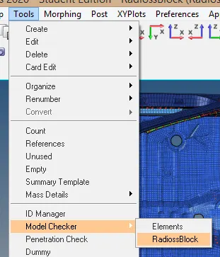
- - For that go to the radioss block command.(Tool>>model checker>>radioss block)
-
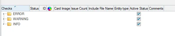
- Here, we seen that no any issue are available, its totally fine.
*
Time-step :0.5 to 0.1 microseconds:-
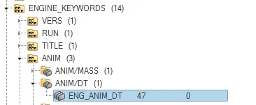
-For that go to the solver>>Engine keywords>>ANIM>>ANIM_DT>>ENG_ANIM_DT
-Here provide the T frequency value is 0.5 micro sec.
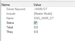
*Run 80 ms:-
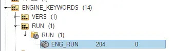
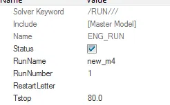
-For that go to the solver>>Engine keywords>>RUN>>ENG_RUN
-here, provide T stop value is 80 ms.
Output requests:-
Creation of cross sections:-
-
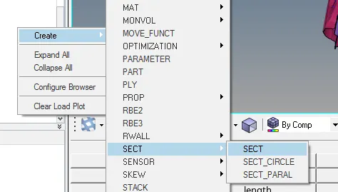
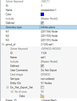
- For cross section creation go to the solver tab and press right click and then create>>sect>>sect.
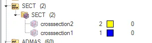
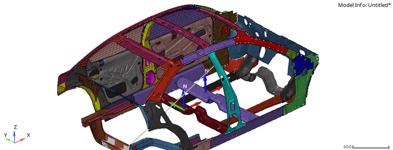
- - Here there are ten cross section creation at various places.
-
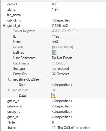
- here main important value is:-
delta T=0.1
alpha=1.67
Iframe=12
-
- After that go to the output blocks.(model>>output blocks)
- - Create new ouput bolck and provide the name is cross_section.
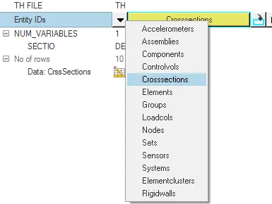
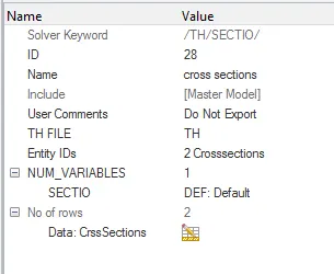
-Here, Entity id selected using crosssection type.
Intrusions:-
-
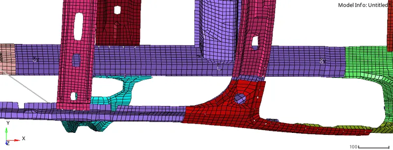
- First of all create skew at particular node.
-
- peak velocity:-
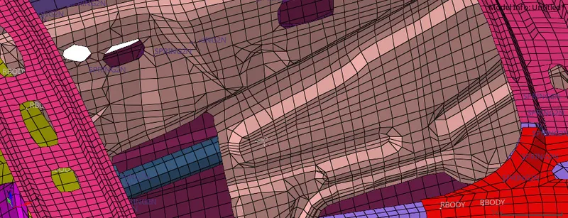 -
- - Now go to the model tab and create new output block and provide the name is intrusion.
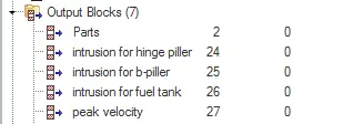
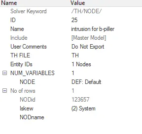
Note:-here selected skew is which we are created. Here also create peak velocity, for a peak velocity origin of skew and node
selection is same.
Run the simulation:-
-
- Now go to the analysis>>radioss.
- provide the name and location.
- - provide the value at opctions is -nt 4.
Results:-.
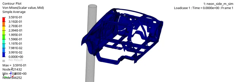
*The following results are obtained for von-mises stresses:-
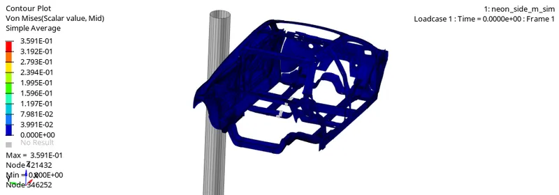
*The following results are obtained for displacement contour:-
*Plot of various energies vs time:-
-For the creation of plots, first of all go to the hypergraphs 2D mode and input the T0 file.
-After that choose below type opction and select various energy.

-Initially internal energy is zero and kinematic energy is maximum value.After the start of simulation kinematic energy is reduce
due to the resistance offered by wall. internal energy is increase due to the consevation of energy.
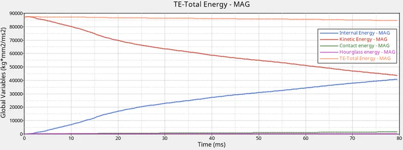
-The hourglass energy is zero during simulation due to the QEPH element formulation.
-The contact energy is slightly increase during simulation.
Intrusion:-
-
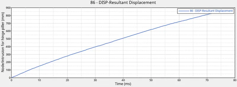
- The intrusion obtain at node 86 is :-
-
- From above plot we find out that the maximum value is 840mm.
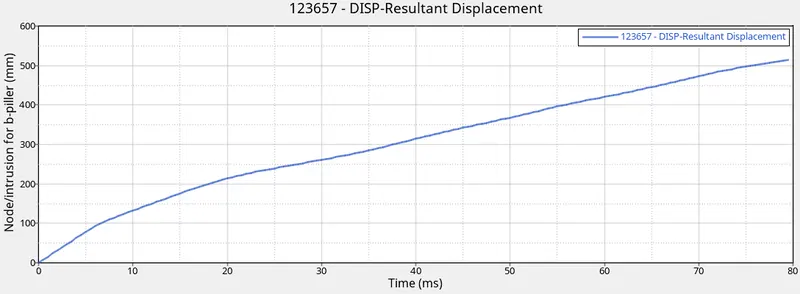
- From above plot we find out that the maximum value is 515 mm.
-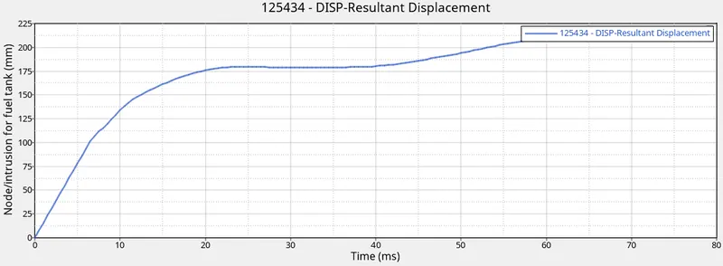
- From above plot we find out that the maximum value is 215 mm.
Peak velocity:-
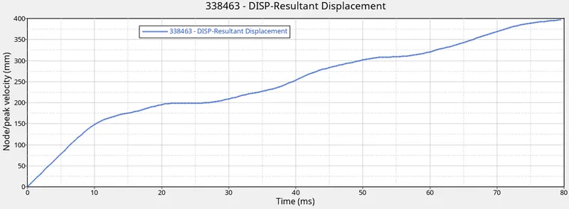
For peak velocity plot setup following condition :-

From above plot we find out that the maximum value of peak velocity is 395 mm.
Rigid wall force plot:-
-For rigid wall plot setup following condition :-

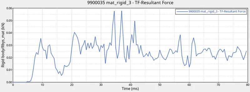
-From above plot it is conclude that there are maximum value of total resultant force for rigid wall is 0.057 KN at 37ms.
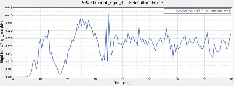
-From above plot it is conclude that there are maximum value of total resultant force for rigid wall is 0.0425 KN at 35ms.
Conclusion
- As per the design, the BIW structure works to dissipate the impact energy by crumpling/crushing as well as transfers it around the occupant chamber such
that least damage is done to the passengers and driver in case of a crash. - As the given model is only a part of the complete assembly as in the 300k element model many of the important components such roof panel, floor
components, body panels etc. are not involved which in real-life conditions will dissipate some of the impact energy lowering the impact forces further
hence the results are satisfactory. - However the added mass of these uninvolved components will result in higher K.E. Causing larger deformations hence, it can be assumed as a tradeoff. So further analysis is suggested for assurance. As seen in the result plots for sectional forces and intrusions, only a fraction of the impact forces are transmitted to the inner structural components, hence
the design can be considered safe.