Assignment 7-Side Pole Crash Simulation Challenge
Aim : Side Pole Crash Simulation Challenge and study of intrusion at fuel tank, B pillar and hinge pillar region, and sectional force experience by chassis members.
Procedure :
Import the geometry (runname_0000.rad ) file to Hypermesh>> radios solver
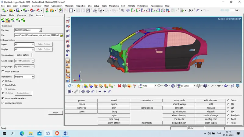
Task 1: Check unit system and either follow [Mg mm s] or [Kg mm ms].
Now we check for unit system used in cad and pre-processor
Model browser >> Card >> BEGIN_CARD
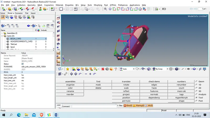
As we checked it follow below unit system
Length : mm; Time : ms; And mass : Kg
accordingly we can say the unit for rest like
force : KN, Stress : GPa, Energy : kN-mm, Gravity : 9.806e-03
Task 2: Create an appropriate interface, friction 0.2, and recommended parameters.
For this we will right click on solver browser >> create >>inter>>type 7
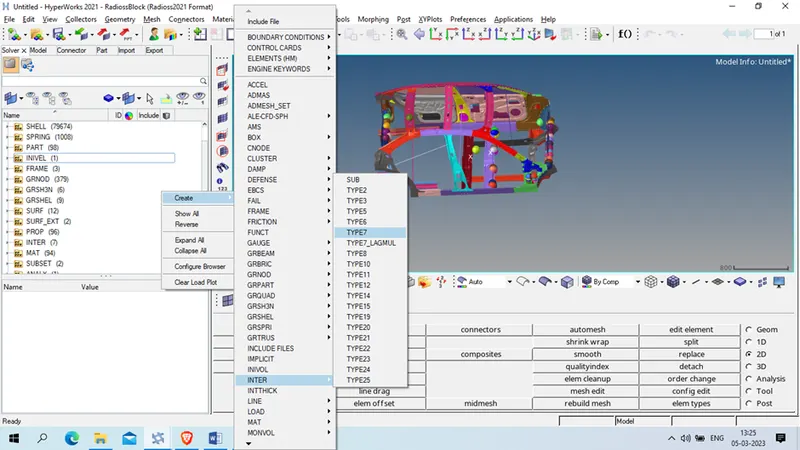
Gmod_id (s): select all component of car
Surf_id(M): Select all component of car
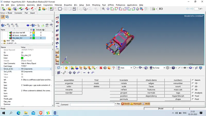
Istf : 4
Igap: 2
Idel: 2
Stmin: 1
Fric: 0.2
Gapmin: 0.5
Inacti :6
Iform: 2
Task 3: Make sure of no penetration and intersections.
For this we will click on tool>> penetration check
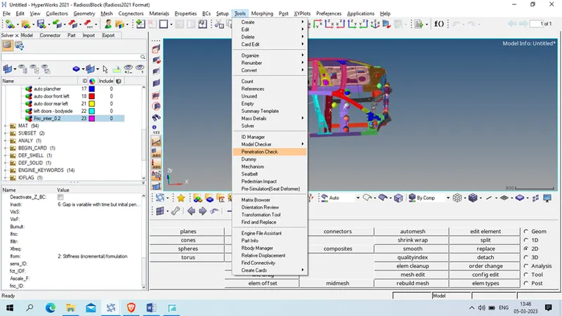
Select the all group and click on check
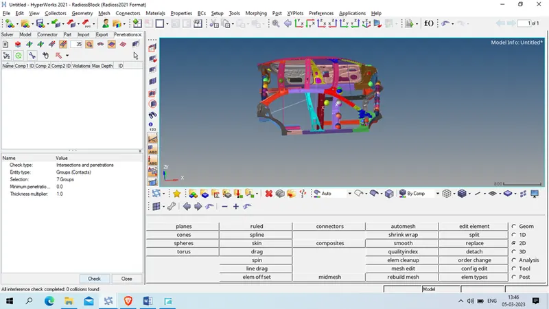
As we have zero penetration and intersecting element so we will proceed.
Task 4: Create a rigid wall with friction 0.1 as per the reference model.
Before Rigid wall we will create temp node at the outermost node of B pill at the left side and take 200 mm offset
Geom>> temp node >> select the location >> create
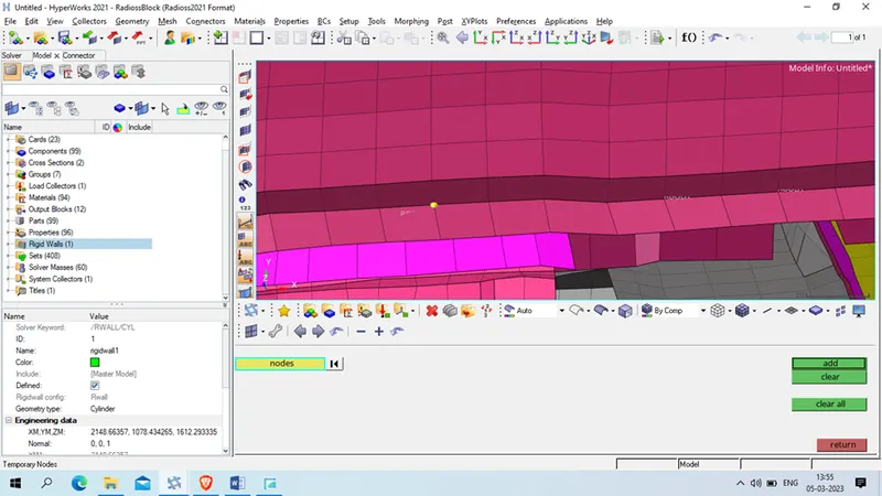
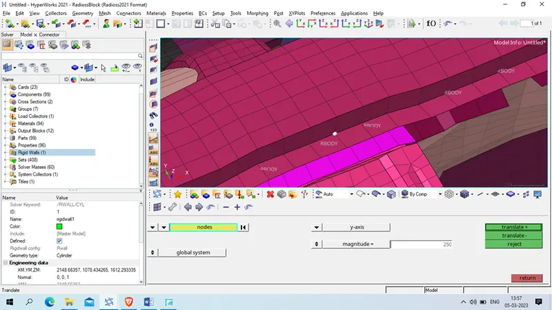
Now translate the node using
tool >> translate >> select the node and duplicate node >> give magnitude in Y axis >> translate +
Now we will create cylindrical rigid wall
Right click on solver browser >> create >> Rwall >> CYL
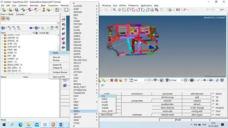
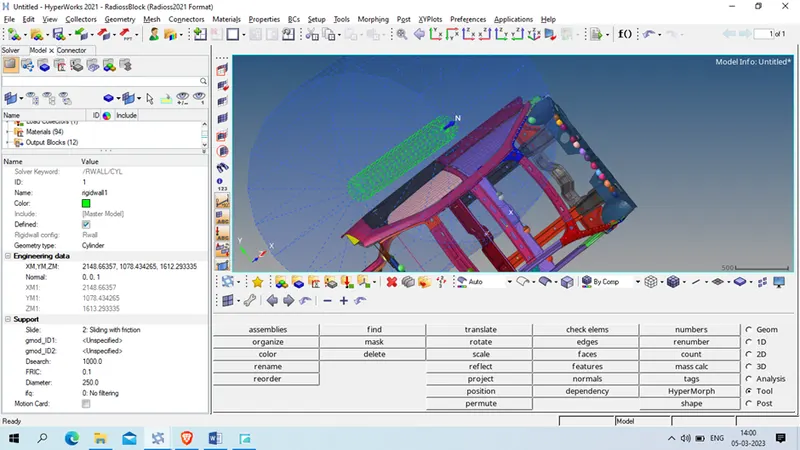
In engineering data : give the node location
normal : x:0, Y:0 z :1
Support
slide : slide and frictional
Dsearch :1000
Fric: 0.1
diameter:250
Task 5: Compare the model weight with the reference model and use added masses to reach the target weight of
Now first check the total weight of the vehicle
Tool >> Mass details >> mass, cog and inertia
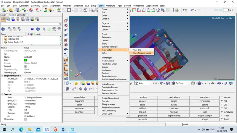
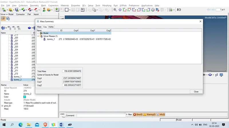
As it have only 165 kg mass , we will add 165 Kg mass so that it will become 700 Kg mass.
To add mass , right click on solver browser >>create >> admas
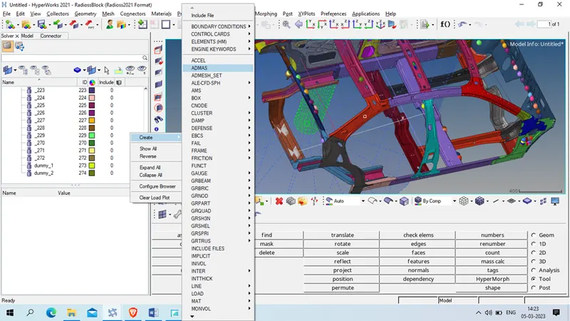
Now select the node as shown below
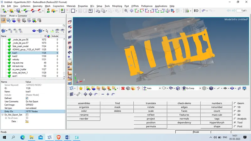
Mass :435
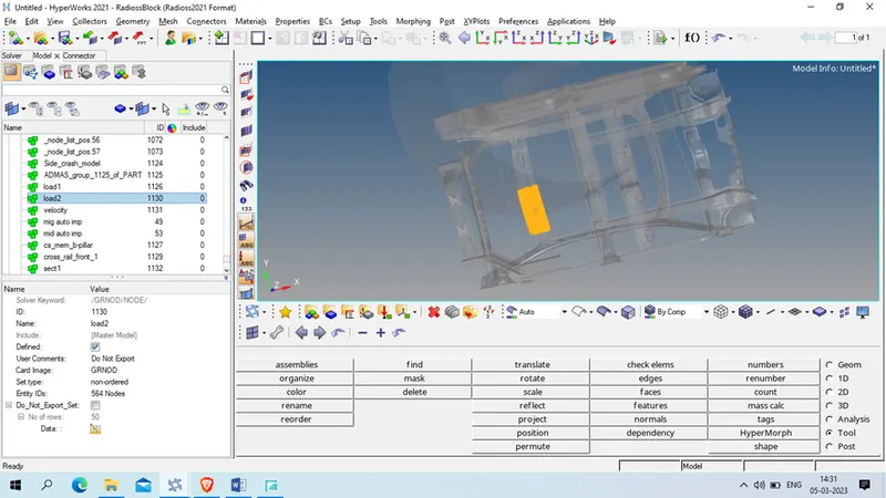
And select below node and assign the mass 100 Kg
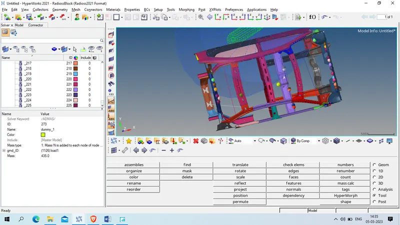
Now check mass and COG of the vehicle , for that tool>> mass >> mass COG and inertia
Task 6 : Initial velocity - 20mph, as per the standards.
First convert 20 mpl to mm/ms which is 8.9408 mm/ms
Now right click on solver browser >> create >> boundary condition >> INIVEL
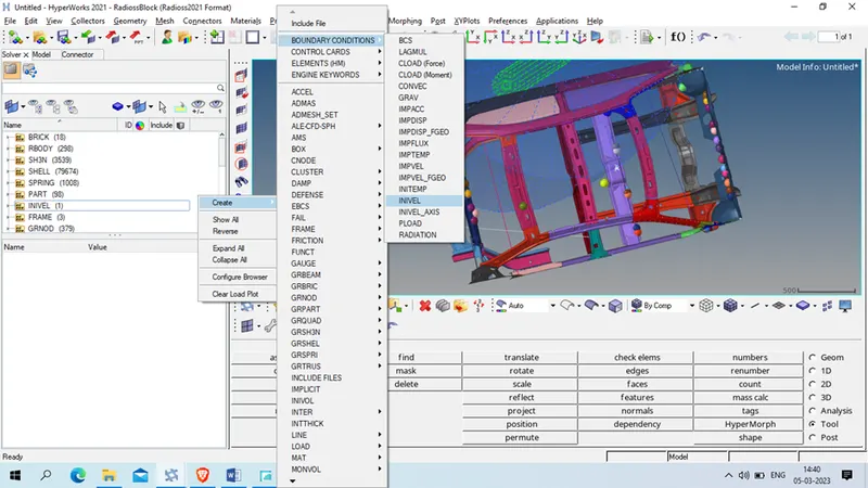
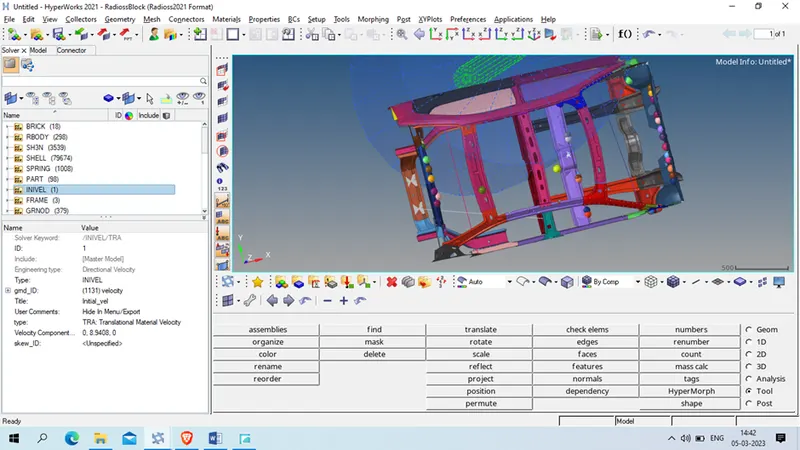
Now select all component in GMD_ID
Type :TRA, translational material Velocity
velocity component : x:0, Y: 8.9409, Z:0
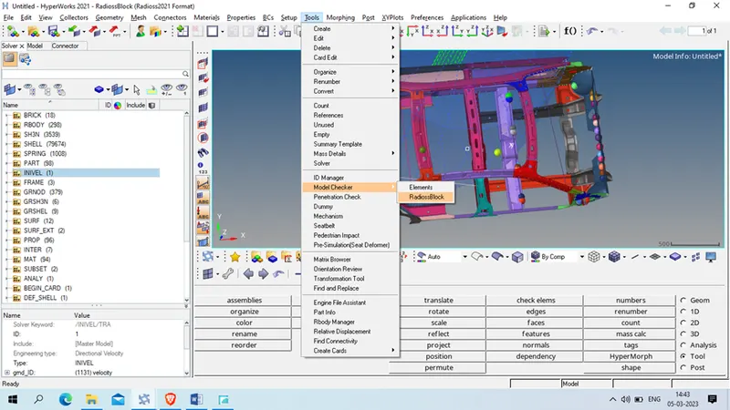
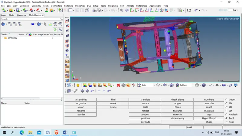
Now check for model checker
Tool >> model checker >> Radioss Block
right click on model checker browser >> run
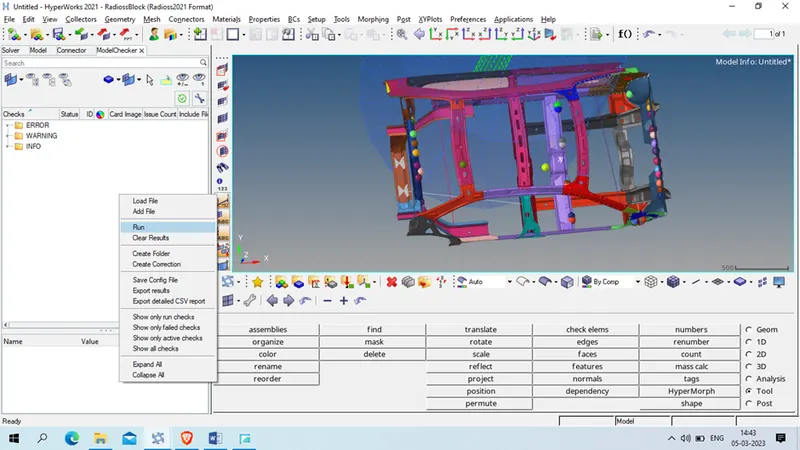
We done have any error , we have only 7 warning so we will proceed
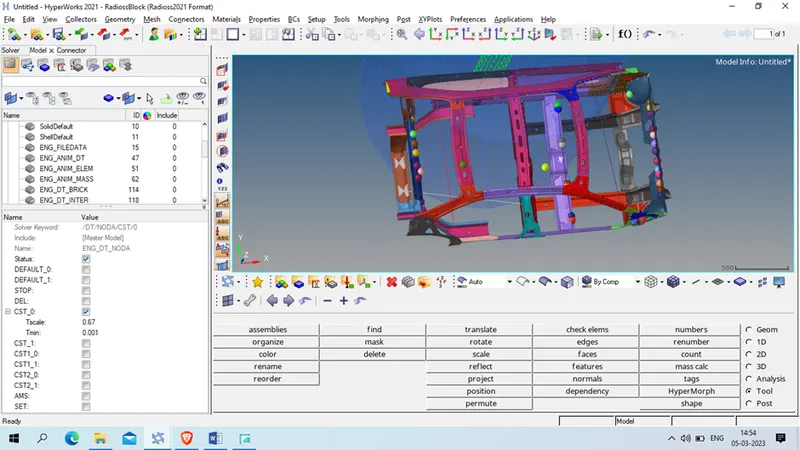
Task 8: Timestep :0.5 to 0.1 microseconds.
To set time step go to Model >>Card>> ENG_DT_NODA
Check CST 0 and give Tscale : 0.67 and t min as 0.001ms
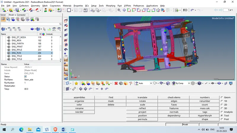
Task 9 : Run 80ms.
Go to model >> card >> ENG_RUN
Tstop : 80 ms
Output request
Task 10 : Sectional force in the cross member.
To create this we will first create mov frame
Right click on solver browser >> create >> frame >> mov
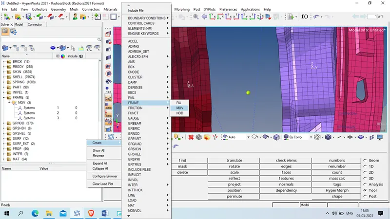
Select origin , z axis and zy plane as shown below
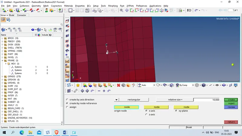
Create same moving frame to the other cross member
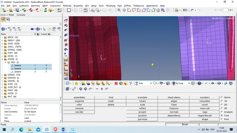
Now create section on this region to measure force passes through thses member.
Right click on solver browser >> create >> sect >> sect
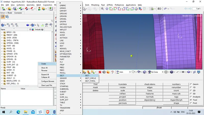
Now select N1 , N2 and N3 as we uses to create Frame ,
Frame Id : 1 ( id of respective frame which we created )
Delta T: 0.1
Alpha : 0.628
Grshel ID : select the element as shown below
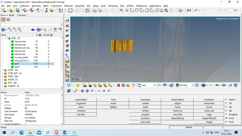
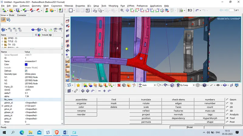
Now repeat the same process to create section and 2nd cross member
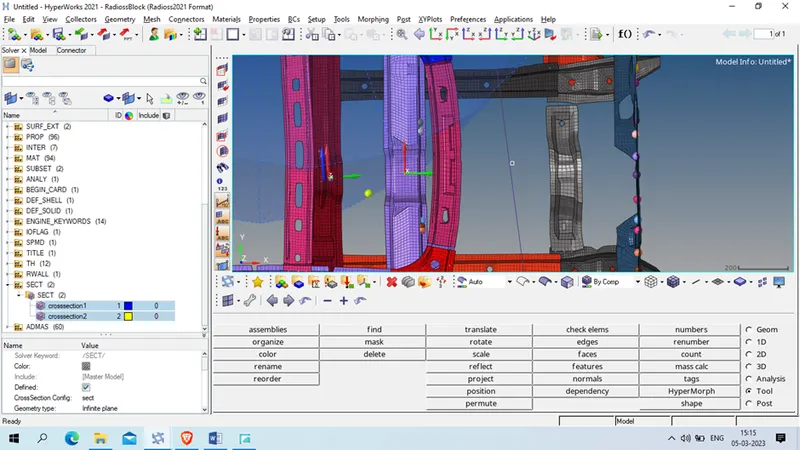
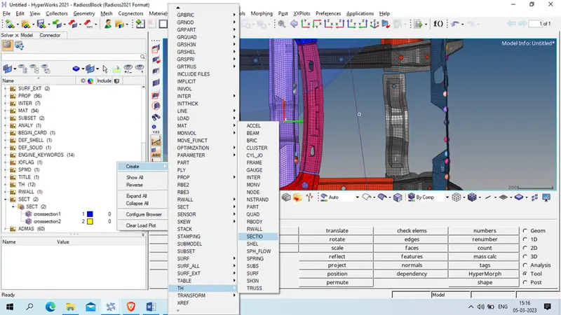
Now create output request for time history
Right click on solver browser >> create >> th >> section
Select entity _id : crosssection 1
Num_variable :1
Sectio : DEF default
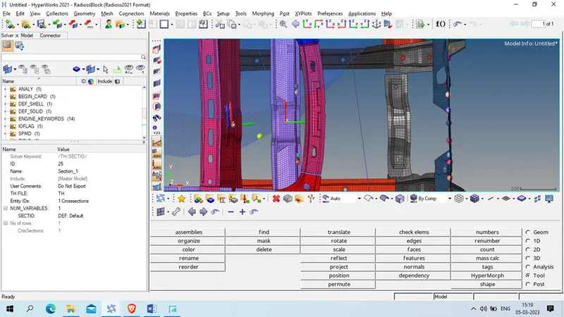
Repeat the same for other section
Task 11: Intrusion at B pillar,hinge pillar and fuel tank region. Provide recommendations on what can help to reduce
To create intrusion we will define spring element at B pillar , hinge anf fuel tank region
1st we will create property for spring element
Right click on model browser >> create >> property
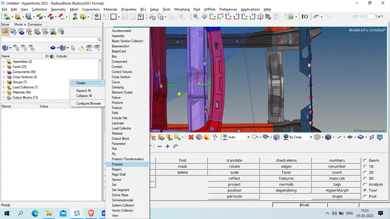
Card Image: P4 spring
Mass : 0.001
K1 : 0.001
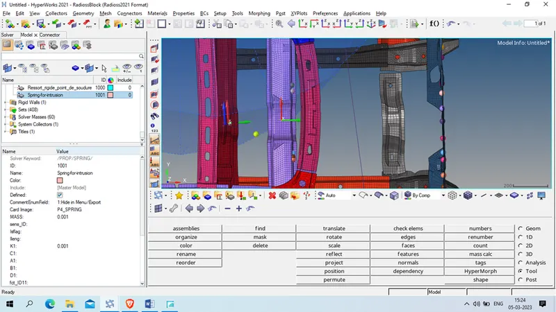
Now we will create 3 property in model >> component >> create
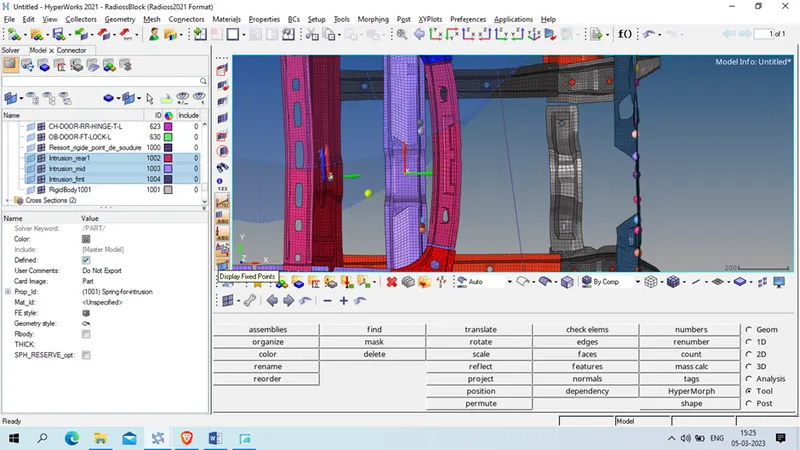
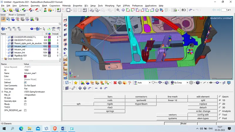
Make intrusion as current collector and crate spring
1D>> springs >> select the 2 node
1 is located at the fuel tank region , and othe is at place which will be stationary while operation, as shown in below
Create intrution_mid as current collector
and create spring at B pillar with 1 node at B pillar which are going to deform an other will we opposite site ,as shown below
Now we will create intrution_front collector as current collector
And create spring using 1D >> springs>> select 1 node at pillar and 2nd opposite side as shown below
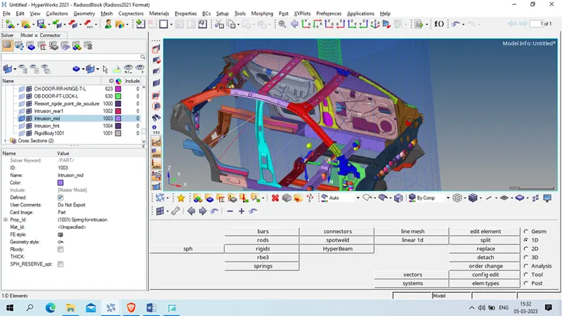
Now assign spring property to the all 3 component
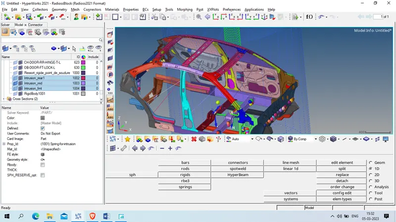
Now create Time history output file
For this right click on solver browser >> create >> th >> spring
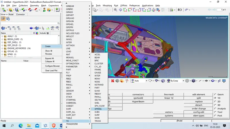
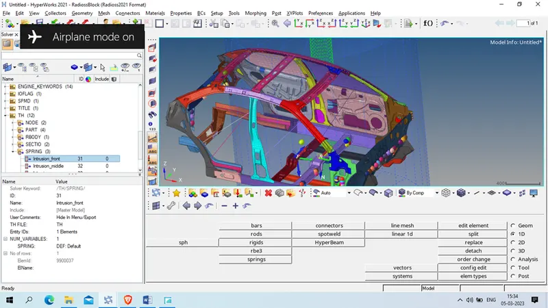
Create 3 TH request 1 for each spring
Num_variable : 1
Spring : DEF default
Task 12 : Peak velocity of an inner node of the door
1st we will create moving frame at required location
right click on solver browser >> create >> frame >> mov
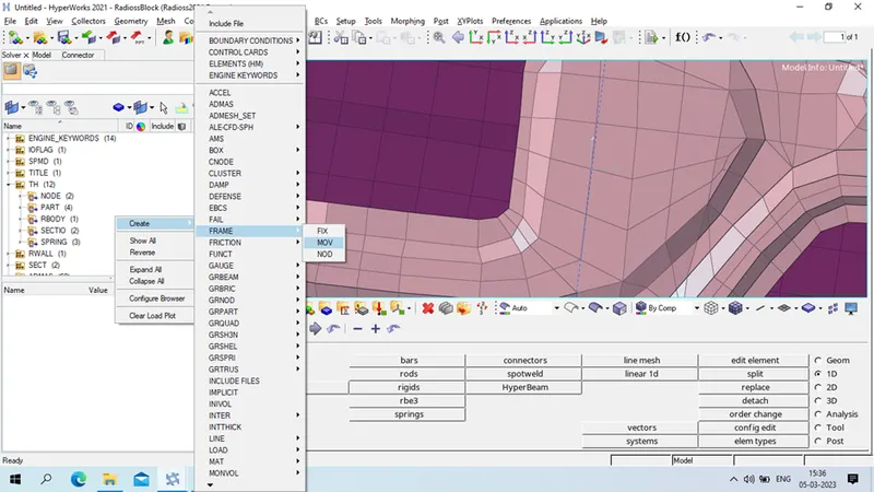
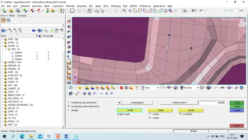
Select the node as shown below
Now we create Th output for this now
Right click on solver browser >> create >> th >> node
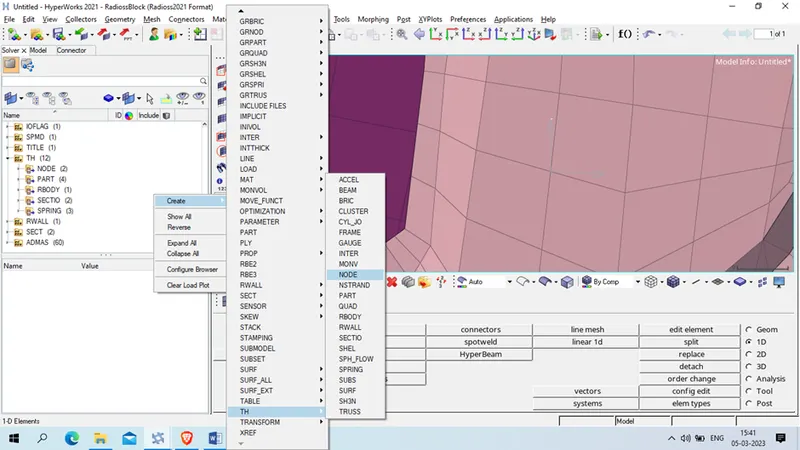
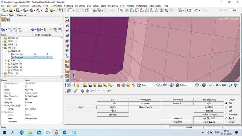
Select the node where we need Th file
Num_variable : 1
Node : DEF default
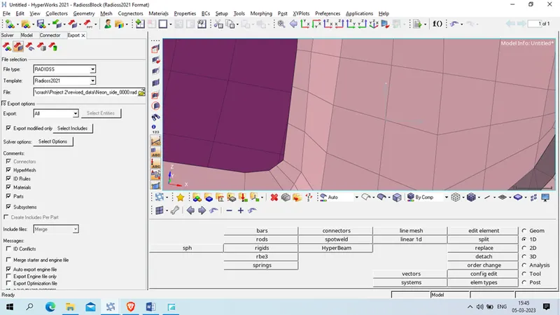
Our model is ready for simulation so we will 1st export the model at desire location
Export : all
click on export
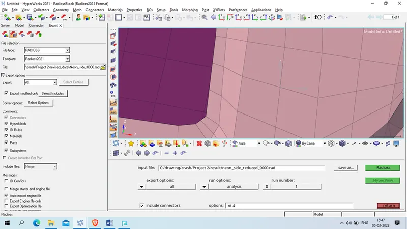
Now we will run for simulation
go to analysis >> radioss
Set the path for result , option : -nt 4
export option : all , check the include connector
Result :
After simulation completed we got ELAPSED TIME : 1:28:47
Energy Error : -1.9%
Added Mass : 0.8119E-02
ANIMATION FILE :
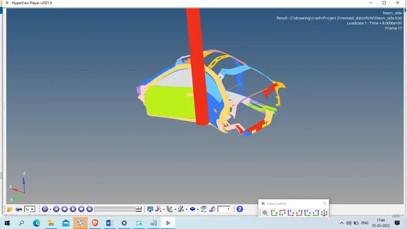
The animation of simulation file is as given below
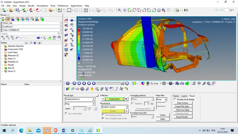
Displacement:
Von mises stress
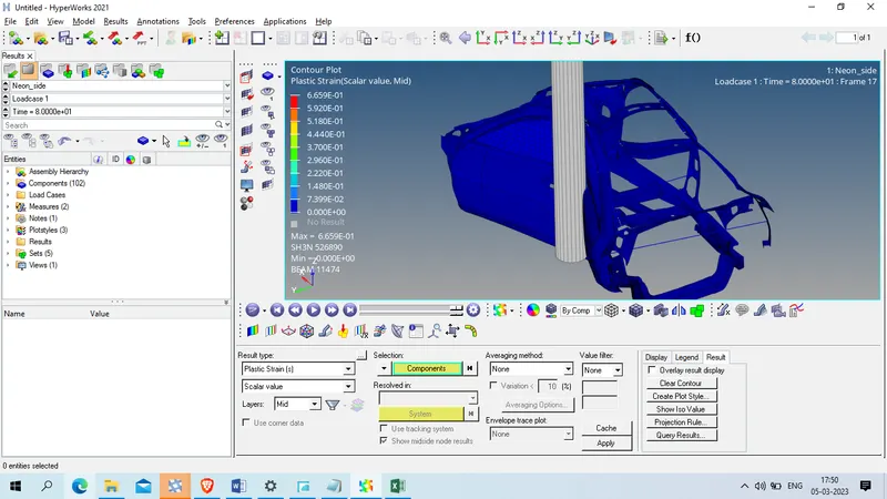
Plastic strain
Specific energy
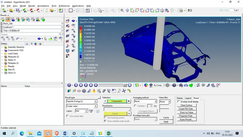
| Max | Min | ||
| Displacement | mm | 7.67E+02 | 0 |
| Von mises Stress | GPA | 3.47E-01 | 0 |
| Plastic strain | 6.65E-01 | 0 | |
| Specific energy | kN-mm | 9.55E+04 | 0 |
Plots in Hypergraph 2D
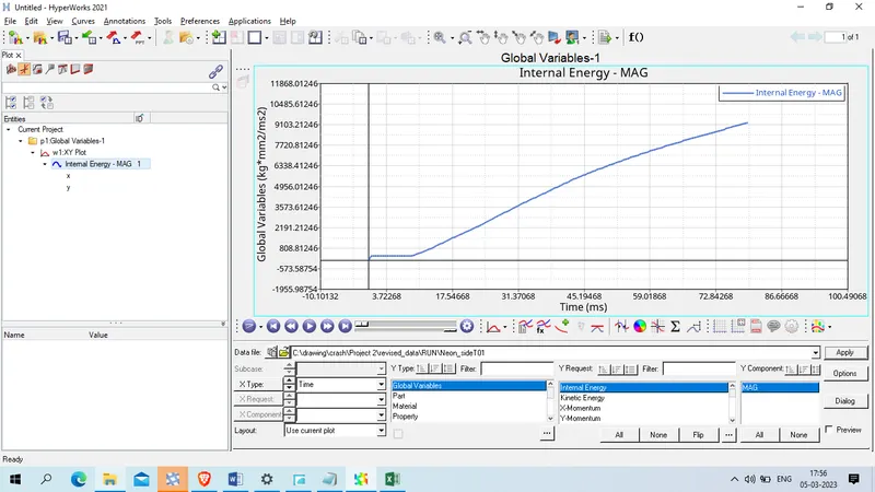
Internal enerygy is shown below
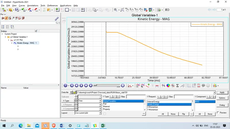
Kinetic energy is shown below
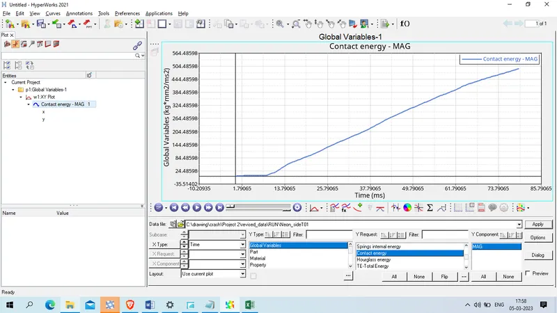
Contact energy plot is shown below
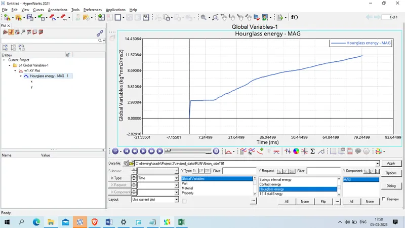
Hourglass energy is as shown below
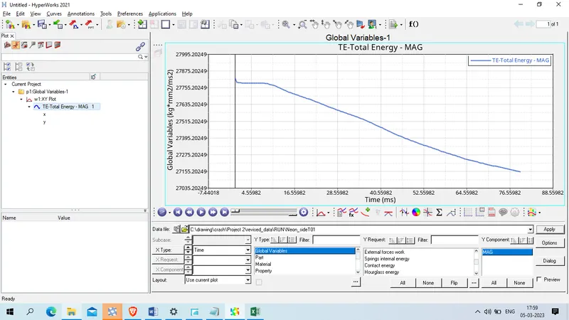
Total energy in system is given as below
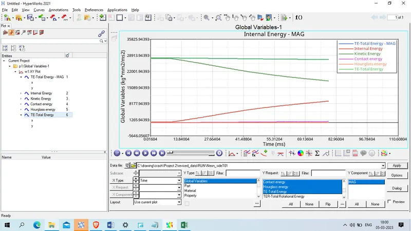
The comparison of all energy is as shown below
Sectional force expriance at the cross sections are given below
1 st cross section total resultant force is shown below
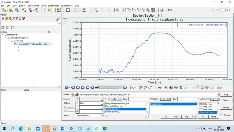
The maximum resultant force expeinace by the 1st cross section is 4.084 KN .
2. the resultant force experiance by the 2nd cross section member is shown below
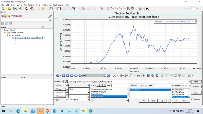
The maximum resultant force experiance by the 2nd cross section is as 4.21 KN .
now we will show intrusion at different point
1. Hinge Region
the intrusion at Hinge region is as shown below
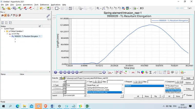
The maximum intrusion was experiance by the vehicle inside was 121.60 mm,
2. B-Piilar
the intrusion experiance by B pillar is shown as below
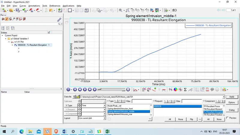
The maximum intrusion experiance by the b pillar is 434.81 mm.
3. Fuel Tank
The maximum intrusion received at FUel Tank portion is shown below
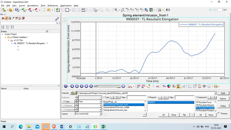
The maximum intrusion experiance by the fuel tank region is 10.61 mm
now we will observe peak velocity at door node.
the velocity of node at door is given as below
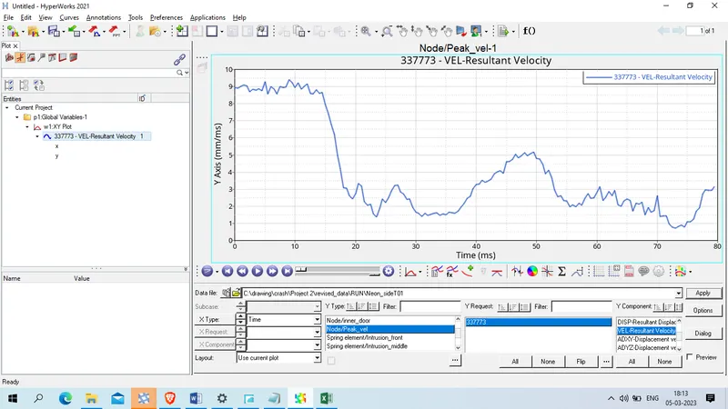
The peak velocity experiance by the node at door was 9.395 mm/msat time of 9 ms .
COnclusion:
The model was simulated for a side pole crash test and the results were discussed.
From the output file the energy error and mass error is in an acceptable range
Work on the B-pillar property improvement as it's the closest part which is comes in the contact with the force during the side crash.