Assignment 7-Side Pole Crash Simulation Challenge
To set up the given simulation conditions on the BIW model for side crash simulation in HyperMesh/RADIOSS and discuss the results .
Neon side crash -BIW
- Check unit system and either follow [Mg mm s] or [Kg mm ms].
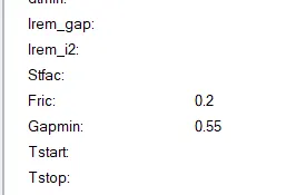
- Create an appropriate interface, friction 0.2, and recommended parameters.
- Make sure of no penetration and intersections.
- Create a rigid wall with friction 0.1 as per the reference model.
- Compare the model weight with the reference model and use added masses to reach the target weight of 700kg while getting CG about the required range.
- Initial velocity - 20mph, as per the standards.
- Use model checker to ensure good quality.
- Timestep :0.5 to 0.1 microseconds.
- Run 80ms.
Output requests:
- Sectional force in the cross member.
- Intrusion at B pillar,hinge pillar and fuel tank region. Provide recommendations on what can help to reduce Fuel tank intrusion.
- Peak velocity of an inner node of the door.
procedure to import geometry
click on the import solver deck option and import the 0000.rad file
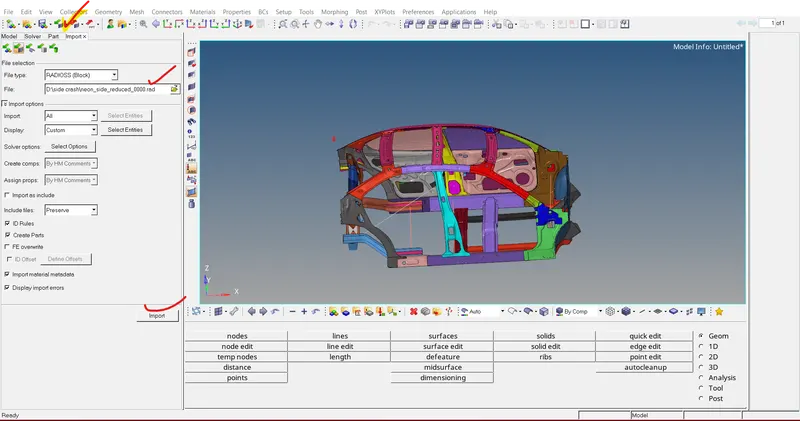
Check unit system and either follow [Mg mm s] or [Kg mm ms].
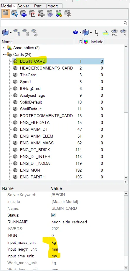
procedure to check unit system
click on the model browser >click on cards>select begin_card below the model browser we can check the unit system assigned and we can change the if required from this card .The current unit system is Kg mm ms(mass length time )
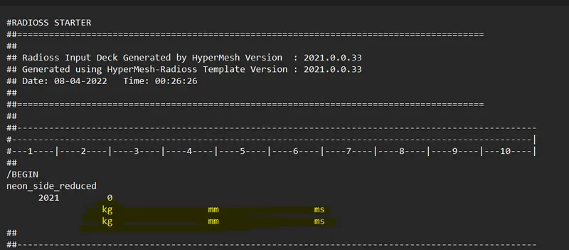
we can also open the stater file(0000.rad) in notepad to make some changes in the unit system
Create an appropriate interface, friction 0.2, and recommended parameters.
in the 2nd case we are going to use the general purpose interface thats is also called type 7 interface .the variables that we have assigned in the type 7 interface are written below.
Interface parameter :
Igap=2 (set variable gape to take into account the true distance between parts )
Gap min : Minimum gap for activation of interface.
Inacti : Action to take if initial penetration exist.
Istf : Affects how the stifness of the interface is calculated (intial contact stiffness)
Iform : Friction formulation
Stmin : Minimum stifness to use in the interface.
Idel : What to do with slave nodes and master segments if element fails (deleted) that they are attached to.
gm : master element gap = t/2 ; t is thickness of master element for shell element.
gs : Slave node gap = t/2 ; t is the largest thickness of shell elements connected to slave node.
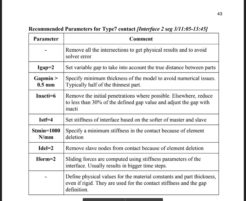
in this model we are going to use the above defined values
procedure to set type 7 interface
right click on the model browser >click on create>select contact and name it as type 7
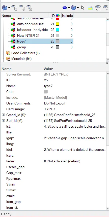
now go to the groups in the model browser and click on type 7 a tab will open just below the model browser
set card image as type 7
click on Grnd_id and click on create >select all the components in the model as slave
click on surf_id>and click on create >select all the components in the model as master
and all other parameters we have to set just like below image
penetration and intersections check
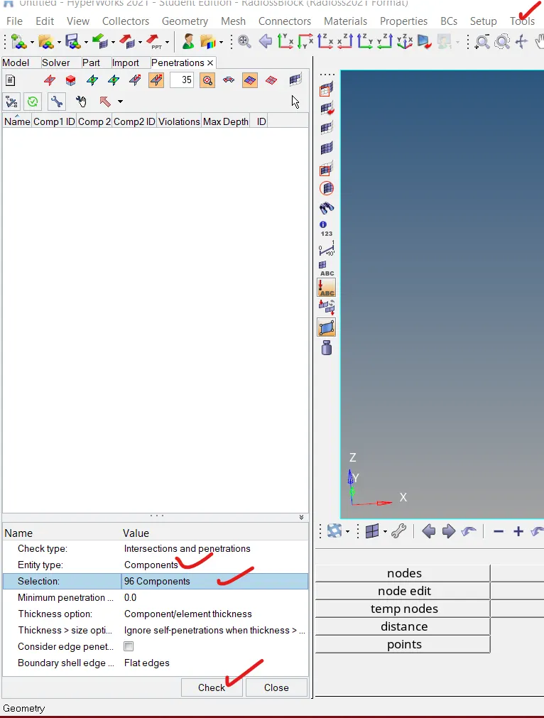
in this case we need to check the penetration and intersection in the model before run,their should not be any penetration in the model
procedure to check the penetration
go to tools >click on penetration check>a tab will open just below the model browser >click on entity id as component >click on selection and select all the 96 components
.CREATE RIGID WALL
procedure to create rigid cylinder
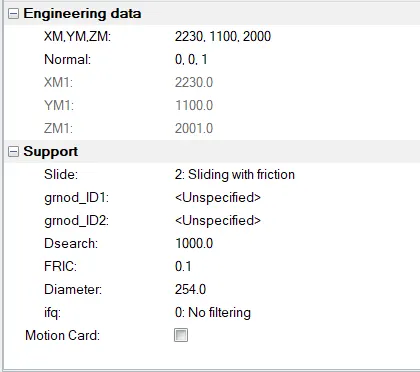
select the solver browser and right click on the tab area >select create option >>click on R_wall AND SELECT CYL a window will open just below the tab area .
from the engineering data click on arrow and select a node on the side door and hit proceed.
from the normal specify the z coordinate 1 so that it normal will bein the direction door.
from the support just specify the below snap values
the diameter of the cylinder is 254mm
Compare the model weight with the reference model and use added masses to reach the target weight of 700kg while getting CG about the required range.
The mass of the given model was about 166 Kg, which is very less for a car model. This mass only made sense if we consider the model which is BIW. However, for running a simulation for the crash, we must consider a car model thus we must add mass to this model.The aim is to reach 700kg while maintaining a proper Centre of Gravity location and also to change the center of mass for the system it will help us to not lift from the side while impact.we have to balance the car while impact
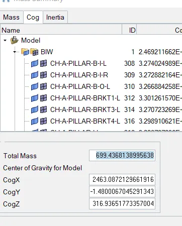
to add the mass to BIW we need to find out the Cog first .to find out the cog click on tool go to mass detail and select mass cocg and inertia a window will open that specify the coordinates of the cog and will tell us the current mass of the car.
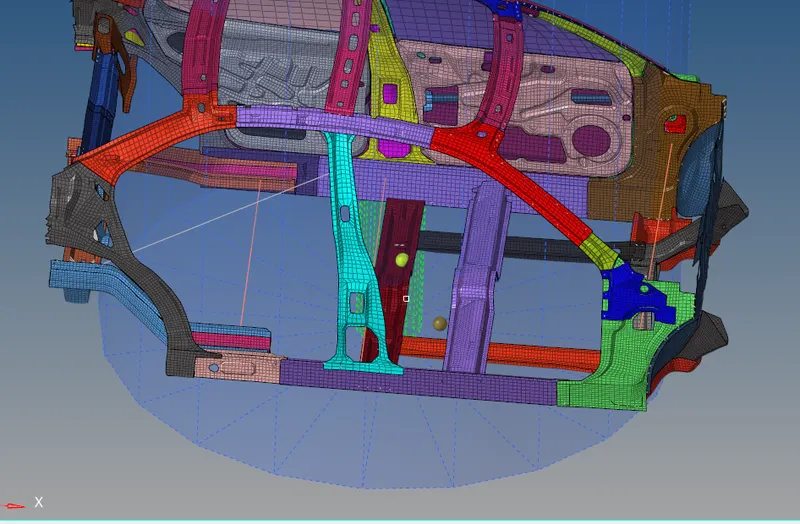
since i have done the mass balancing as shown in below snap .The total mass of the car is 699kg and the Cog lies on the coordinate (2463,-1.48,316) is we go to the geometry pannel and select node option and specify the coordinate values a node will be highlited in the area where our COG lies
Go to Solver browser > Right-click > ADMAS
Select type 1 which will distribute the given mass over the selected area
Specify /INVEL
Initial velocity - 20mph, as per the standards (Given)
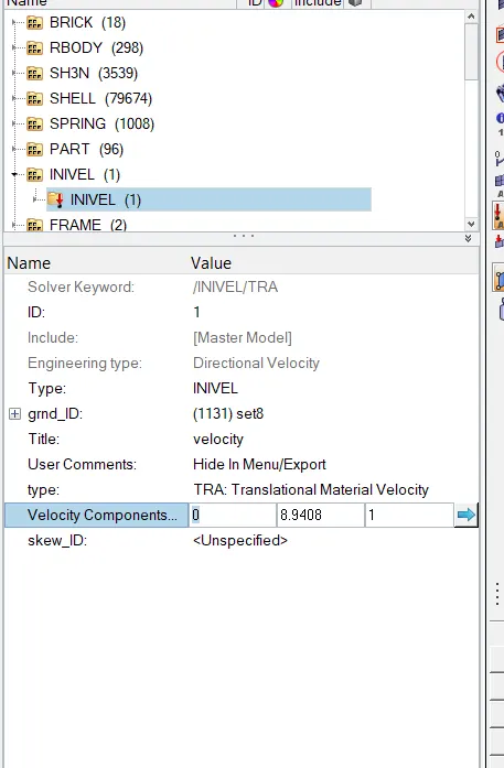
The velocity input for this simulation as per the given condtion is 20mph so when we convert it to m/s by just multiplying it with 0.4470 and the input velocity will be converted to (m/s) 8.94m/s.
To create a velocity
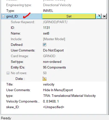
Go to solver browser >> Create >> boundary conditions (BC) >> Inivel
Define the Node group on which specified initial velocities are applied (grnd_ID1). For our simulation, we will be selecting all components
set the velocity component in y cordinate to 8.94
FRAME AND SECTION
We will be Creating Sections at cross members in order to Study the sectional forces. We want to know how the forces are transmitted from the door through cross member to other side of the car and the rate of deformation. It is done in order to ensure the safety of the passenger.
Certain components have to deform more than the other so that the forces that are distributed correctly leaving very little force left to transmit inside the cabin.
FRAME
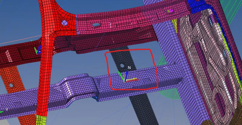
procedure to create frame .
Right click from the solver browser >click on create>select frame a window will open from the pannel >select the origin node >select the x or z cordinate >select the plane yz or yx plane as shown below
SECTION
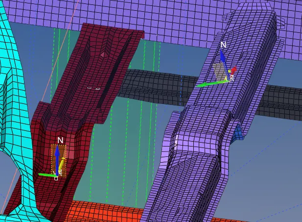
right click in the solver browser >select SECT>click on the section in the solver browser >select the 3 nodes N1 N2 N3 >select the frame ID and click on systems to select the frame >set the alpha =0.1 and dellta=0.6
Define the cutting plane by a group of elements and its orientation by a group of nodes (grshell_ID)
the section has been created as shown in below image
similarlly we can use the same procedure to create section and frame for the remaining cross members
SPRING ELEMENTS (intrusion)
Intrusion at B pillar,hinge pillar and fuel tank region.
to know the deformation after the impact we are goin to create springs on the above components
to study the intrusions (forces inside the cabin causing deformation/rupture).
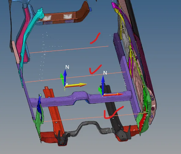
Create 3 parallel spring elements.
Springs can be created from the 1D Panel > Springs
To create a spring first as temp node at that particular selected node then select another node on other to see deflection after crash simulation
After adding nodes now
Go to 1D page >> Springs >> Select first and Second node >> Create spring
CREATE PROPERTIES TO SPRINGS:
To create spring property
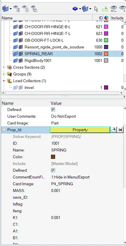
Go to model Browser > Create > Property >Rename as Intrusion springs
After creating a property, a new tab will open there we have to select CARD image as P4 SPRING and Mass as 0.001, and Stiffness as 0.001
module 2
Output requests
- Sectional force in the cross member.
- Intrusion at B pillar,hinge pillar and fuel tank region. Provide recommendations on what can help to reduce Fuel tank intrusion.
- Peak velocity of an inner node of the door.
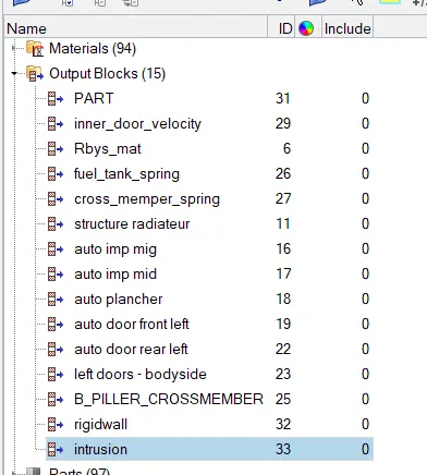
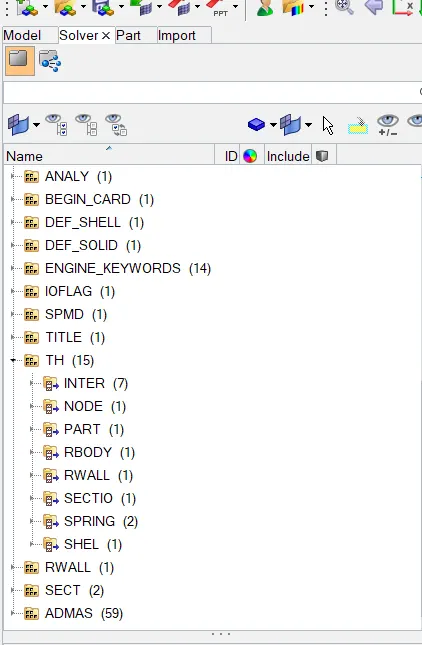
Go to the solver browser > Right click> TH
Under TH, we have a lot of options. We have requested INTER output for the Type-7 interface, SECTIO option for all the sections, and SPRING option for intrusions.
Once we create all these TH cards, we have to select the respective elements for them.
For example, select spring elements for SPRING, INVEL for Intial velocity, and so on
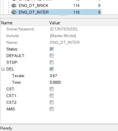
TIMESTEP CONTROL
|
Engine Card |
T SCALE [Scale factor] |
Tmin [Critical Timestep] |
Description |
|
ENG_DT_NODA |
0.67 |
0.001 |
Mass is added to the node when the computed timestep becomes smaller than the critical timestep. |
|
ENG_DT_BRICK |
0.9 |
0.0001 |
Controls the timestep by small strain formulation on the elements if they cause the timestep to drop. |
|
ENG_DT_INTER |
0.9 |
0.0005 |
Uses the default constant timestep method. |
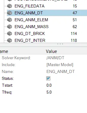
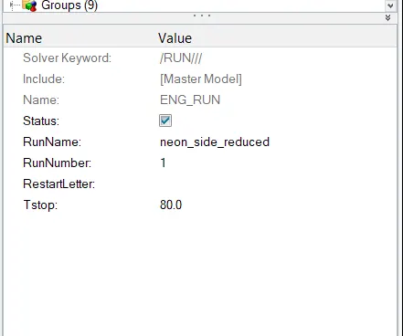
Enter T stop as 80ms and T freq as 5
Go to ENG_RUN enter T stop as 80ms
For T freq
Go to ENG_ANIM_DT enter T freq as 5
Model checker
To check any error in the model we are going to use model checker
go to tools and click on model checker and select radioss block
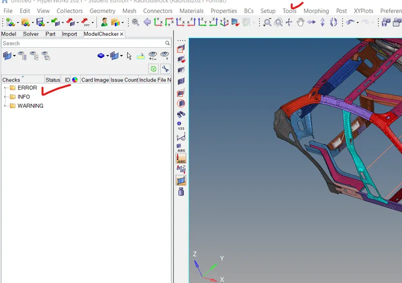
to run the model checker right click in the model checker browser and run the model the check the error if any.
in my model i didnot face any error message but some warnings are shown and those can be ignored and now we are good to go for the analysis
click on analysis and select radioss make sure you have mark include connectors
now save the file in the drive and click on radioss

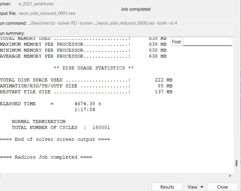
after hitting the radioss a consol window will open just below in the snap
the simulation takes 1 hr and 17 minutes to complete the job
total no of cycles =160001
Results
energy and mass error check
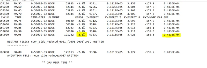
the energy and mass error are within the acceptable range as shown in the above snap
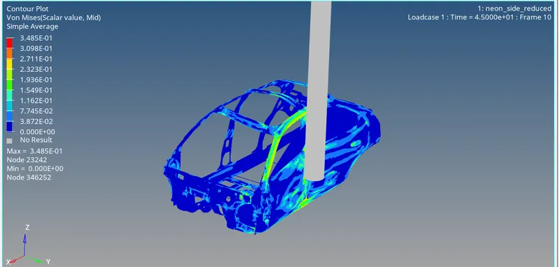
von mises stress
the maximum stress has reached to 0.348Gpa as shown in the below contour plot
From the Von Mises stress plot, the stress distribution is good in the vehicle after the crash. There are very few areas where the stress concentration is more . Generally the stress is more at B-pillar and cross members as B-pillar takes the initial impact and then the impact is transferred to the cross members.
From the simulation, we can see that initially, the car is hitting the R-wall cylinder with a velocity of 20mph, here the first impact can be seen at B-Pillar and after few milli sec the forces is going to transfer to the left and right and front direction in the roof rail and cross members in the bottom as shown in below snap. In each stage, transfer of force is going to reduce because energy absorbed by the components.
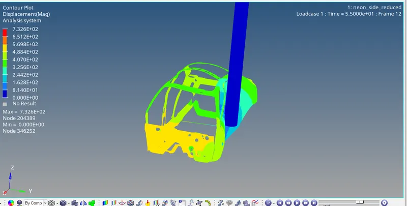
Displacement contour
the maximum displacement has attained a value of 732.6mm
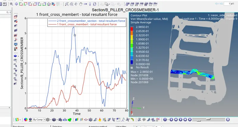
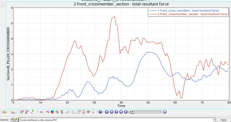
Resultant forces in cross members
cross members plays an important role in the side crash .these members are going to control the side impact by absorbing lot of energy.from the below plot is it clearly seen that the cross member which is in contact with the B pliller is under high stress this means that the member is on the same way as the Rwall cylinder the rwall is going to hit the door first followed by B piller.the maximum stress in the cross member (connected directly to B piller) has reached to 5.5KN at time 37ms while the maximum force in front cross member has reached to 3KN
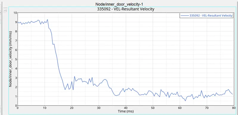
Inner door velocity(at node 335092)
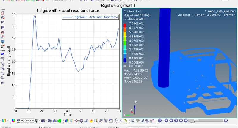
from the plot below (inner door velocity and Rwall ) it is clealy seen upto 13 ms the initial velocity is mantained 8.9m/s or 20mph. once the Rwall impacts the door first we can see that there is sudden drop in the velocity upto 18ms.this means there are some resistive force that are being applied to the RWall cylinder. After 18ms the velocity of the node decreases gradually and mantains between 1 and 2m/s.
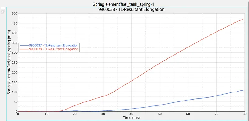
INTRUSION AT PILLER B AND FUEL TANK
intially there is no deformation in the spring element once the Rwall Cylinder is going to impact the body the change in length is going to take place in the spring elements .From the below plot is is clearly seen the that the maximum displacement is going to occur at B_piller and is about 475mm since we already know that B piller is in the same way as Rwall cylinder hence the displacement at B_piller can be seen maximum as compared to the fuel tank which is near about 110mm
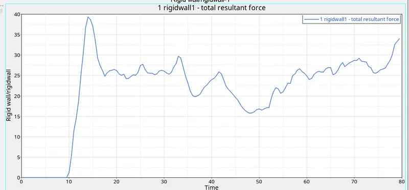
the forces that are exerted by the Rwall force we call them Rwall forces upto 10ms there is no contact between the body and Rwall once the body come in contact with the Rwall cylinder the rigidwall cylinder is going to exert some force to the body .The Rwall force takes a maximum value of 39KN at 14ms after that deformation is going to take place and Rwall forces goes on decreasing when there is peak in the Rwall forces it mean there may be some crushing of the component or may be a new component is going to occur that has not deformed yet.