Assignment 7-Side Pole Crash Simulation Challenge
Side Pole Crash Simulation
Objective:
To perform a crash analysis on the side of a BIW, also known as a side crash. The analysis is to be carried out for deformation and the forces created as a result of the crash at a speed of 35 mph.
The aim is to simulate for following problem statements;
• Sectional force in the cross members.
• Intrusion at B pillar, hinge pillar, and fuel tank region.
• Peak velocity of a node on the inner door panel.
Procedure:
Import the model:
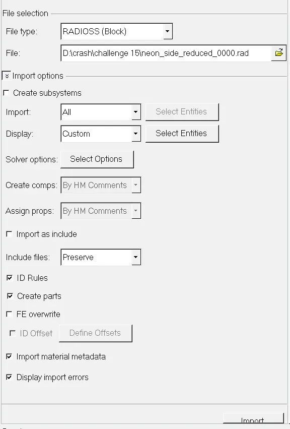
Import the '.rad' starter file of the model,' neon_side _reduced_0000.rad' in Radioss using Import Solver Deck option.
Unit System:
For units, browse
Model > Cards > BEGIN_CARD
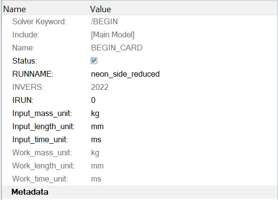
Mass unit : kg
Length unit : mm
Time unit : ms
Penetration and intersection:
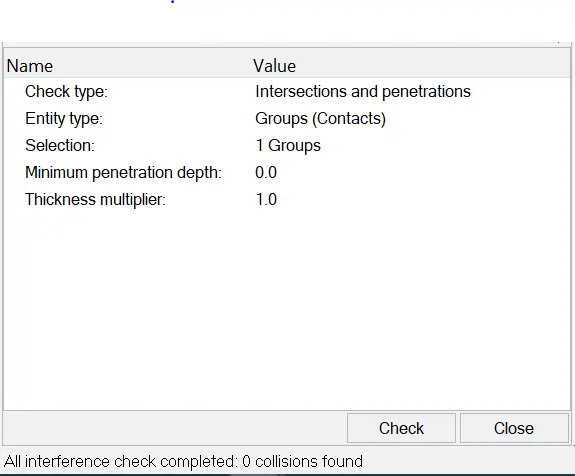
Zero penetration or intersections found.
Reach the target weight of 700 kg while getting CG about the required range:
Existing weight of mesh geometry: 119 kg
Required weight : 700 kg
Additional mass to be added: 581 kg
To add additional weight to achive the required weight ,
Solver > addmas
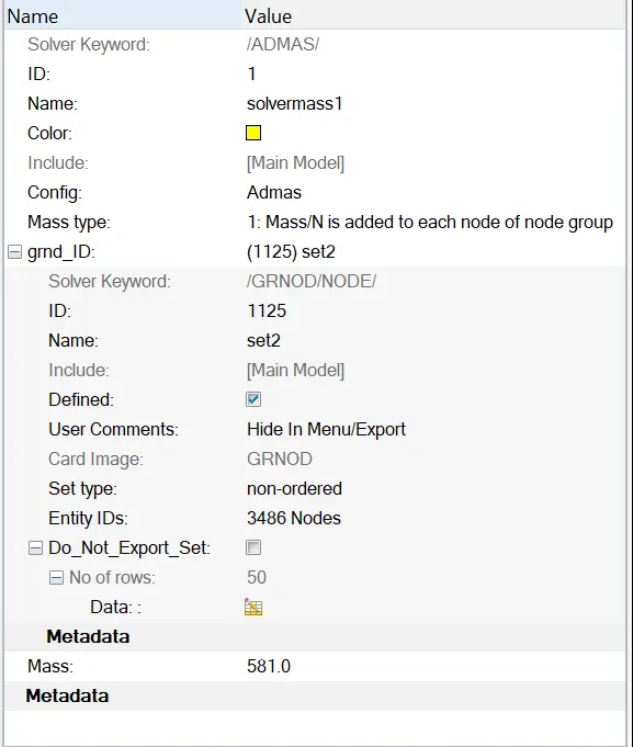
following is the achived COG location,
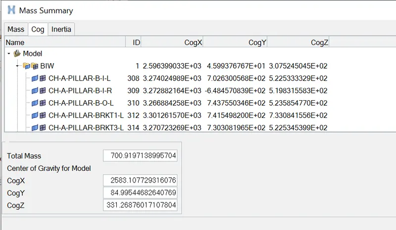
Applying initial velocity:
solver > create > boundary conditions > inivel
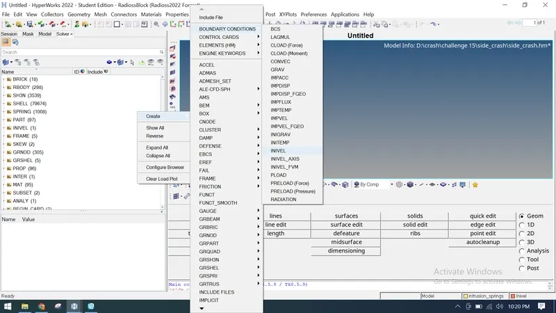
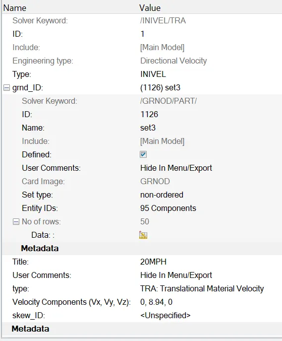
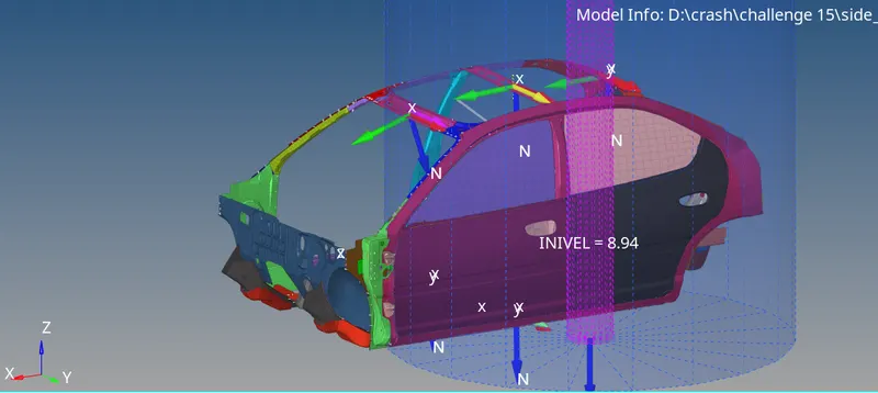
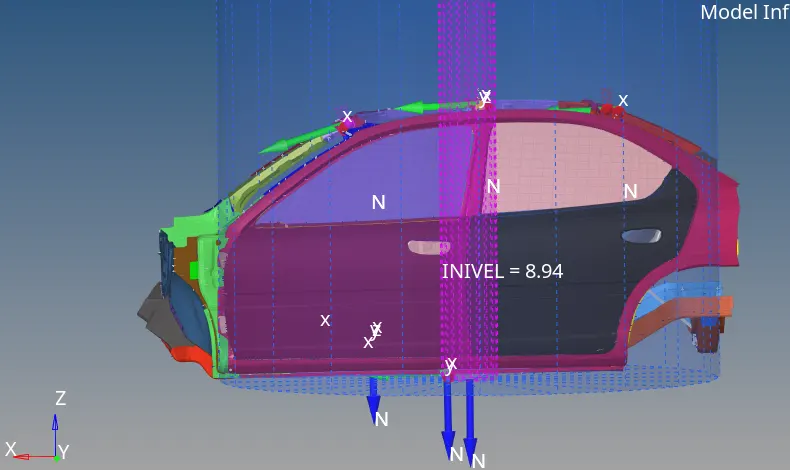
the velocity need to be applied is 20Mph,
since, the units are kg mm ms , thefore the value to input is 8.94 mm/ms
Contact interfaces:
Solver > inter
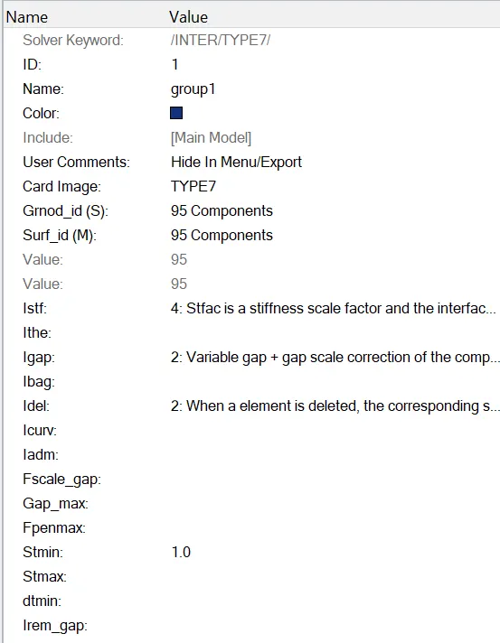
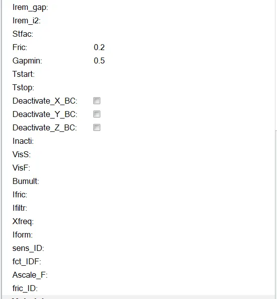
A type7 contact is created between all the 95 components with friction coefficient as 0.2,
Cylindrical rigid wall (pole):
To create a cylindrical rigid wall at the left side of the car, creat the outermost node at the front left door of the car. Using temp nodes option.
Then right-click in
solver browser and navigate to Create > RWALL > CYL.
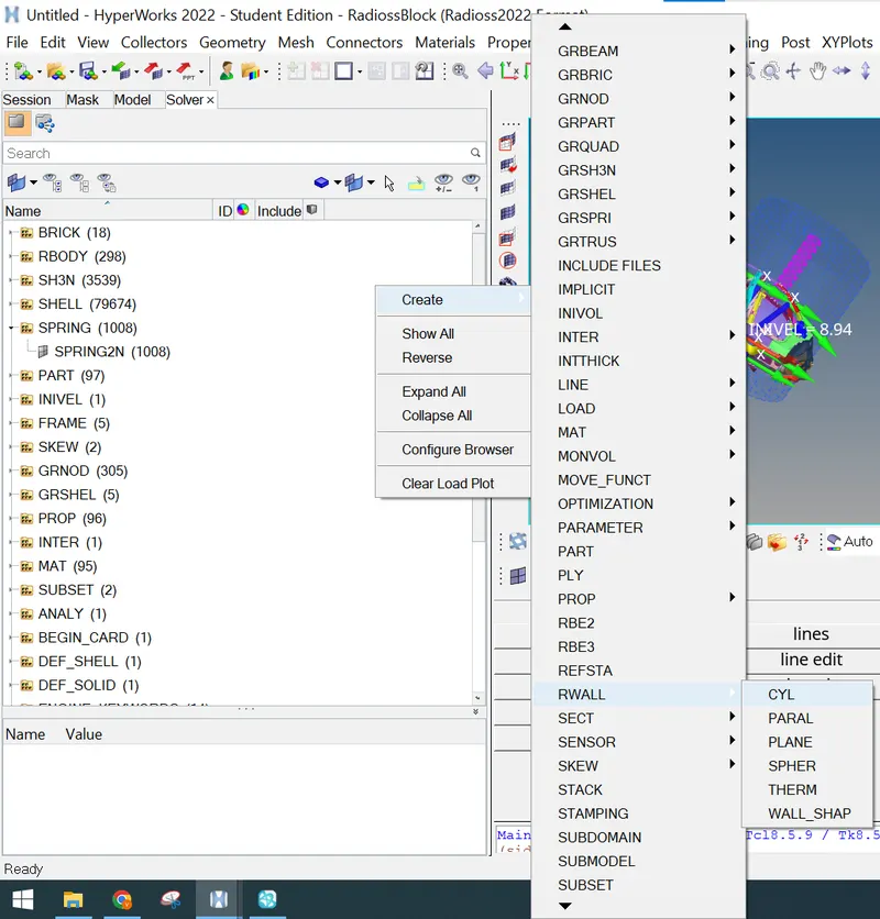
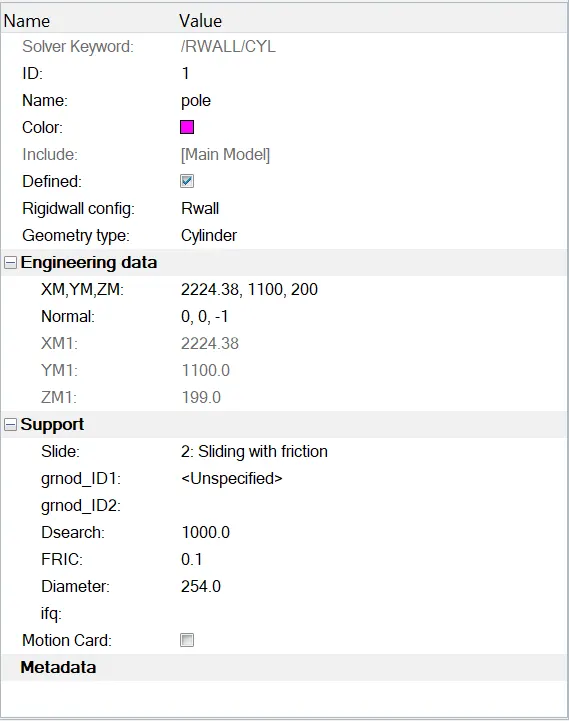
In the RWALL panel, under Engineering data specify the coordinates of the pole.
The normal direction to the pole is in Z- axis and diameter of the pole is 254 mm. The FRIC value will be 0.1 and search value will be 1000 as shown below.
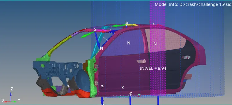
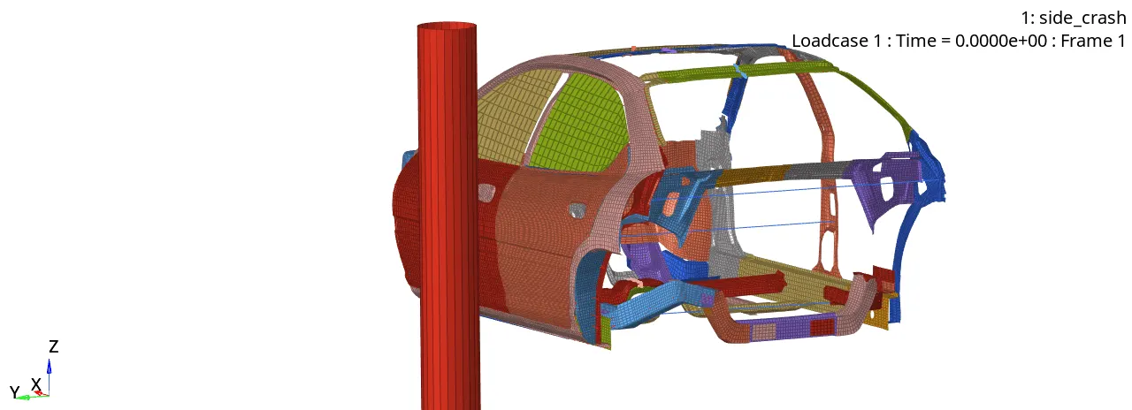
The rigid cylindrical wall created is displayed below;
Cross Section:
For the required results cross sectional is created which are calculated based on a frame of reference. So before creating cross section,create moving frames on a particular node of that section. Now as the moving frames is created which are also called as local axis, the local axis needs to be aligned to the global axis.
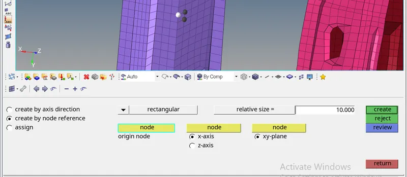
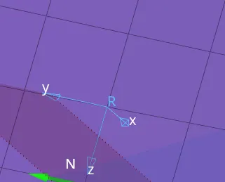
Once the moving frame is created,next step is to create cross-section for the frame. To create a cross-section,right-click on the Solver browser, navigate ,
Create > SECT > SECT
In section panel, specify the Frame_ID.
Right click and create grshel _id on the same panal, select the elements where the cross sectional is required for appropriate results.
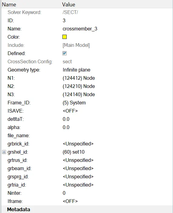
Frame created is displayed below;
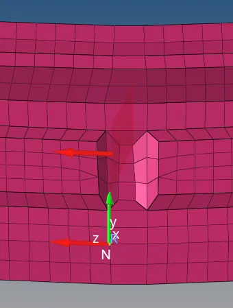
similar process can be followed for different crossections and results;
Intrusion measuement setup:
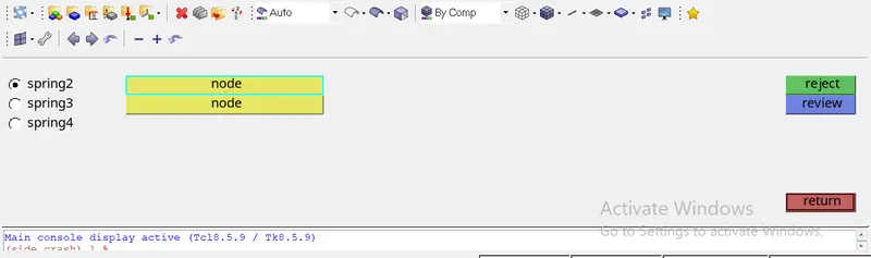
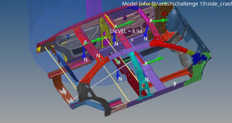
Here, its asked to find the intrusions at B-pillar, hinge pillar and fuel tank. So to find the results at the specified parts, create spring between pair of B-piller, Hinge-piller and fuel tank wall, for creating spring;
1D > SPRINGS > SPRING2 , select 2 nodes;
Spring created are displayed below;
Create the property card for spring with spring stiffness 0.0001
Time History Plot:
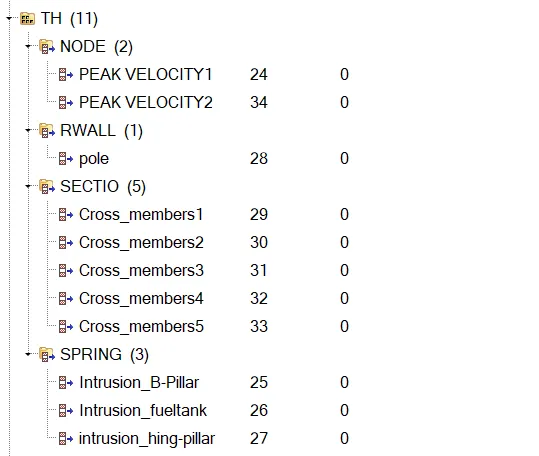
For springs , creat spring plot in output th plot similarlyfor rigid wall, sections and nodes.
the created th plots are displayed below;
Time step and Run time:
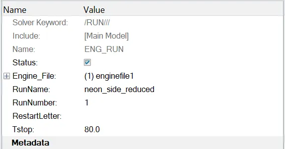
The run time is kept to be 80ms;
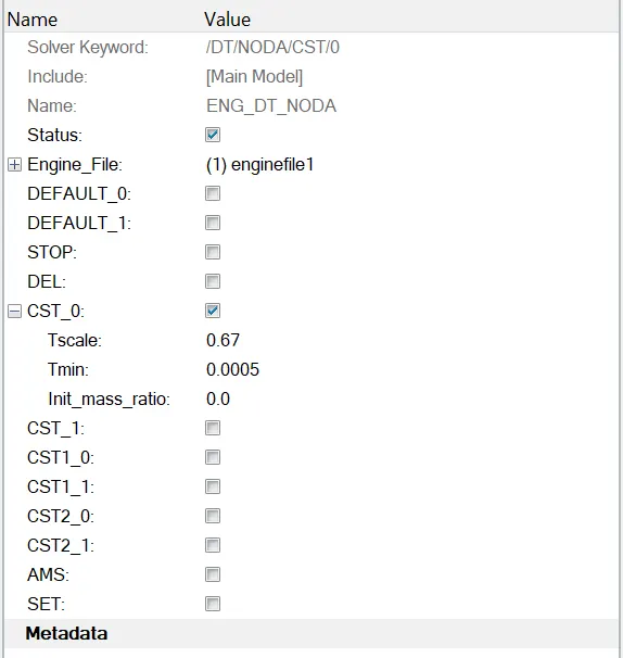
in ENG_DT_NODA, Tmin is kept to be 0.0005 micro second as shown below,
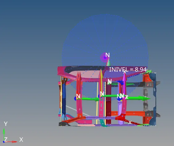
Symulations setup is displayed below ;
Symulation run:
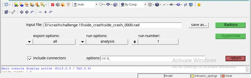
Now, the model is ready for symilation,
before running the symulation the model is checked using radiossblock , to check ;
Tools > model checker> radiosblock
once the check is successfully done the model is ready to run for analysis.
Results:
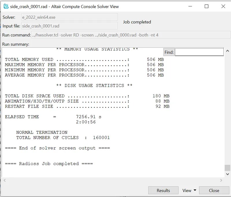
The symulation was run successfully with zero errors and warnings with run time 2:00:56,
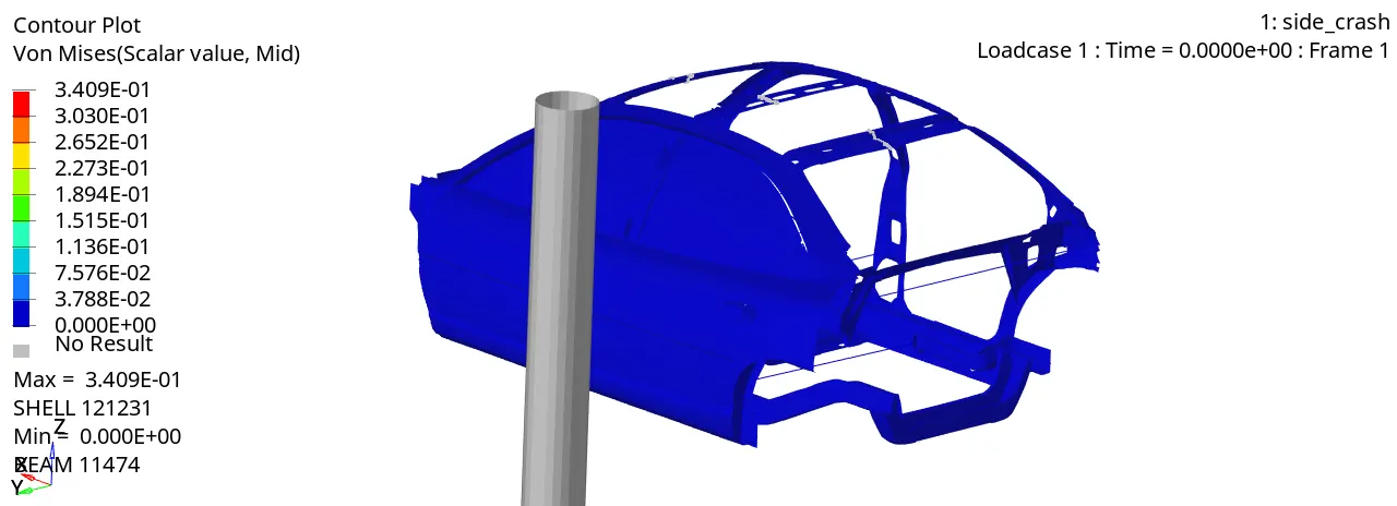
Max stress of 335Mpa is observed.
Von Mises Stress counter plot:
After 26ms, the cross sectional forces are observed to rise drastically.
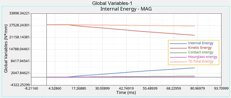
Internal Energy:
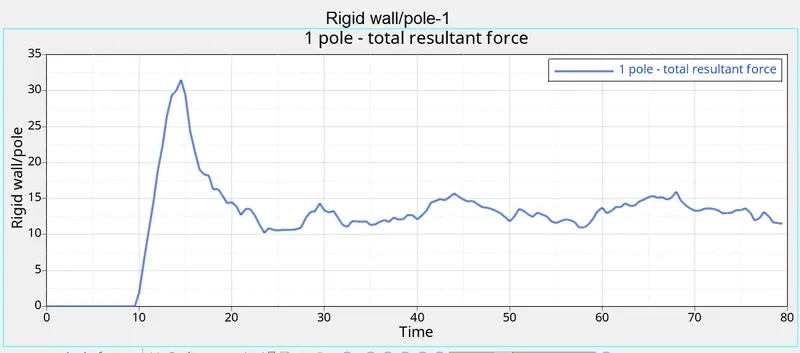
Rigid Wall Forces:
Sectional force in the cross member:
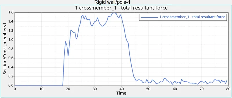
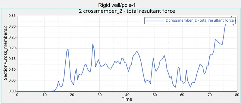
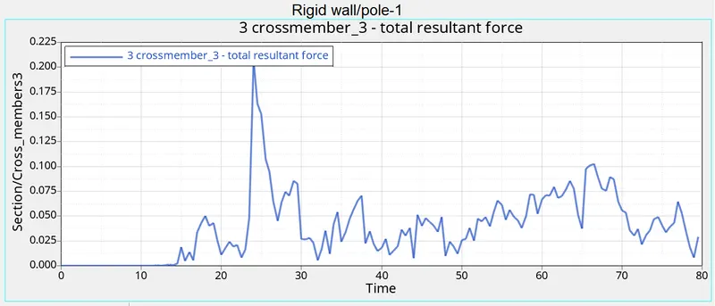
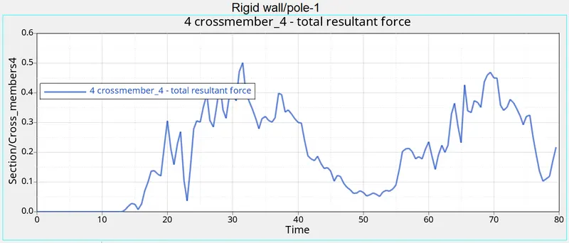
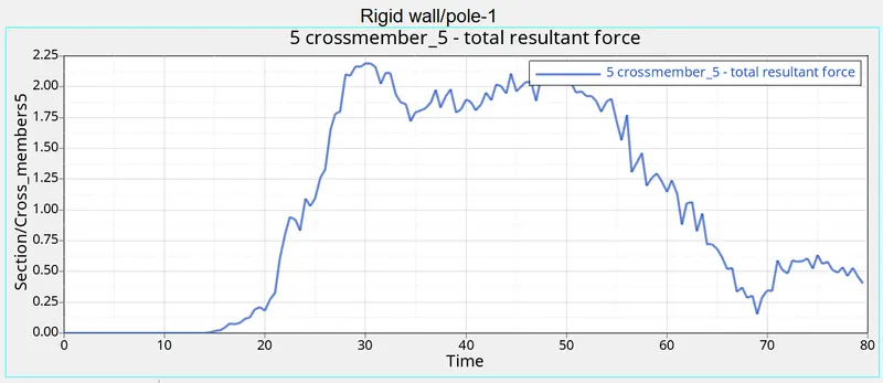
Therefore from the above results the maximum section force is found in main crossmember is ,2.18 kN at 3ms.
Peak velocity at inner door:
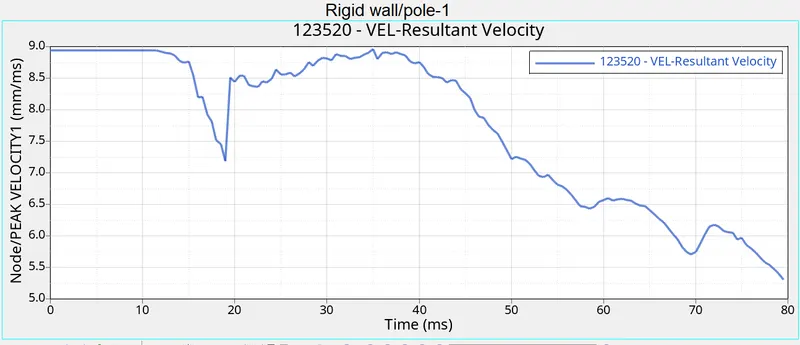
From the above results the peak velocity for the inner node of the door,It can see that node is stable and maintaining the initial velocity of the car 8.94mm/ms untill it crashes into the pole. Once the crash has started sharp decrease in the velocity at the node is observed i.e 7.188mm/ms. So, after the crash has taken place due to inertia a rise in velocity is experienced i.e the maximum or peak velocity which is 8.5 mm/ms.
Intrusion at B pillar,hinge pillar and fuel tank region:
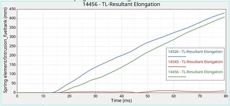
B pillar region:Blue
Fuel tank region:Red
Hinge pillar region:Green
The maximum intrusion is experienced between B pillar which is found to be 430.32mm where as the minimum intrusion is experienced at fuel region of 11.42 mm, at hing pillar region the experienced intrusion is 409.8 mm.
To minimise the intrusion at fuel tank region stiffners can be added perpendicular to wall surface or ribs can be added for better flow transmission, or use of superior material such as composit fibers dependinding on cost to weight ratio.
Conclusion:
- Side crash analysis was carried out on the given BIW model as per requirements.
- The output requests were also generated after the creation of cross-sections in each of those regions. Peak velocity and intrusion values were also measured at certain points of the model.
- From the output file the energy error and mass error is in an acceptable range so it can be concluded that the simulation is pretty stable.
- Cross-members A and B are playing important role in the Impact force absorption. So, improving the cross-member material or adding some extra support element near the cross member can improve their performance.
- To minimise the intrusion at fuel tank region stiffners can be added perpendicular to wall surface or ribs can be added for better flow transmission, or use of superior material such as composit fibers dependinding on cost to weight ratio.