Simulation of a side - crash scenario of a Dodge Neon BIW using FMVSS 214P.
Objective: To conduct a simulation of a Side Crash for Dodge Neon BIW based on the guidelines below:
-Check the unit system of the model
- Create an appropriate interface, friction 0.2, and recommended properties.
- Make sure no intersections and penetrations arise in the model
- Correct rigid bodies
- Impart an initial velocity of 35 mph
- Run the model checker
- Compart the weight of the model with the full-scale model provided to us and reach a target weight of 700 kg while moving the C.G to the expected range
- Timestep: 0.5 to 1 microsecond
- Run 80 ms
Output request:
1. Sectional forces in cross-members
2. Intrusions at B-pillar, Hinge pillar, Fuel tank
3. Peak velocity at the inner node of the door
Side - Crash:
Side crashes account for about a quarter of passenger-vehicle occupant deaths in the United States. Protecting people inside crashes is challenging because the sides of vehicles have relatively little space to absorb energy and shield occupants, unlike the fronts and rears, which have substantial crumple zones. Automakers have made big strides in side-protection by installing side airbags and strengthening the structures of vehicles.
Side airbags, which today are standard on most new passenger vehicles, are designed to keep people from colliding with the inside of the vehicle and with objects outside the vehicle in a side crash. They also help by spreading impact forces over a larger area of an occupant's body. However, side airbags by themselves are not enough. Strong structures that work well with the airbags also are crucial.
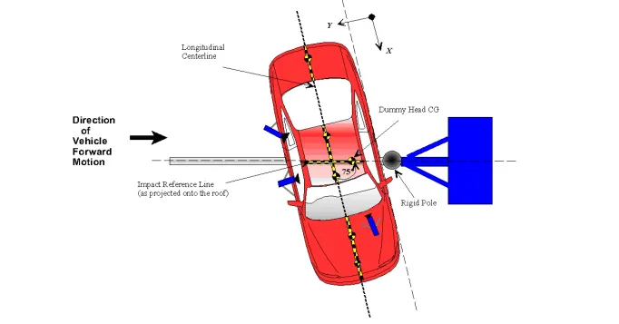
For this side crash analysis onto a rigid-pole, FMVSS 214P has been followed
https://www.nhtsa.gov/sites/nhtsa.dot.gov/files/tp214p-01.pdf
Full-car model:
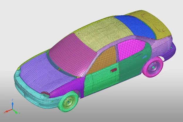
The above file has been provided as a reference for setting up the model and it assists in going for a model quality check of the BIW structure provided to us.
From the above full-scale model, we need only the mass of the vehicle. Using mass balancing tool in hypercrash, the weight of the vehicle comes out to be 1216 kg.
BIW Structure study:
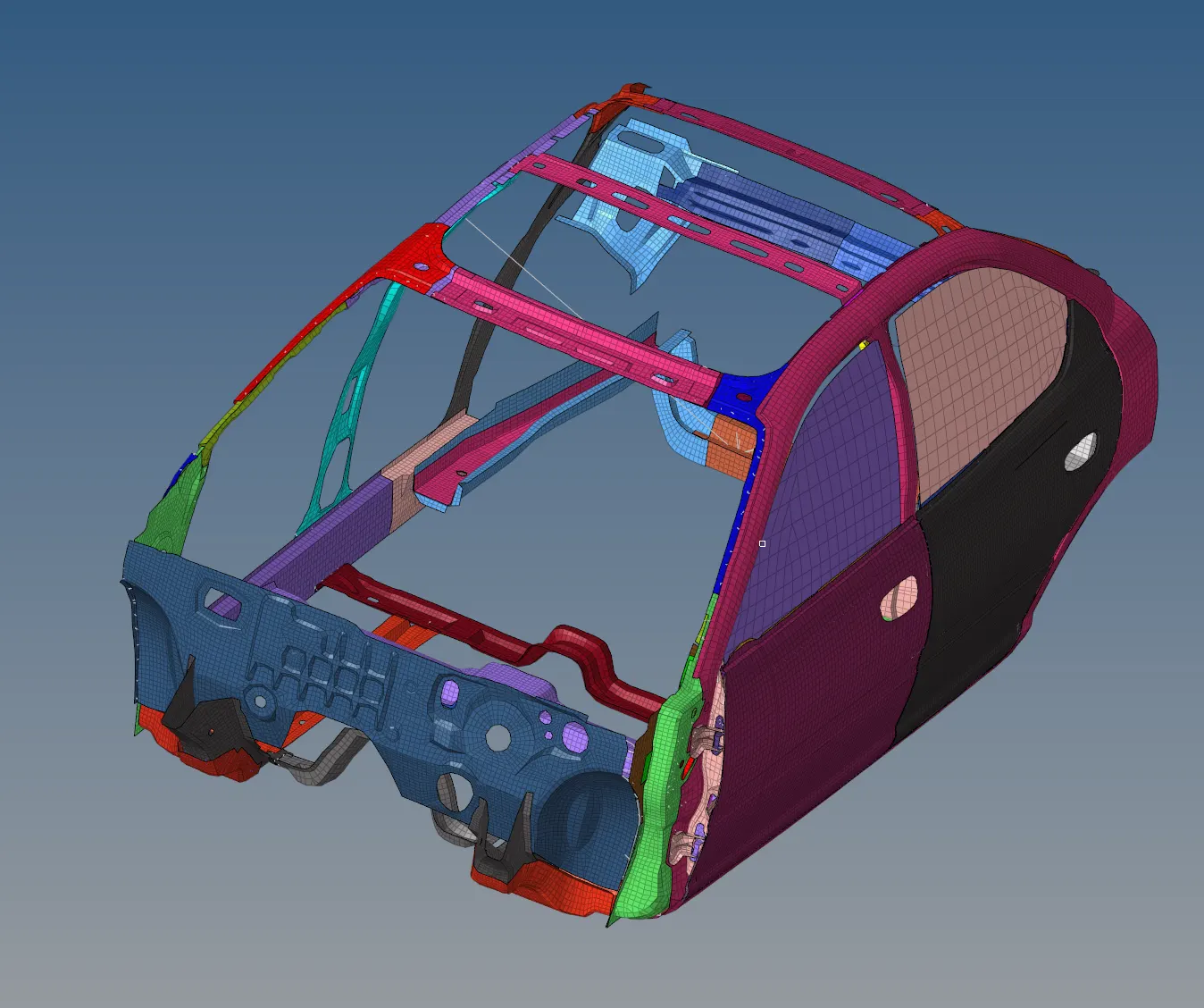
The partial BIW structure given to us contains 95 components. Each component is described by a unique property and there are 94 material cards used to define this BIW structure.
Around 298 rigid bodies constitute the components. However, many of these rigid bodies are being defined for very few nodes. This is to represent the actual behavior of a full-scale model. 7 contact interfaces are provided in the current model and none of them are required for the simulation. It is also noted that around 58 additional masses are present in the model with most of these being of 0.001 kg. These additional masses neither help nor harm the simulation in any way. They can be deleted from the model.
An interface exists in the system of Type 1 (Elastic interface).
Model setup:
Based on the provided guidelines, the units system used for this simulation is [kg], [mm], [ms]
1) Setting up interfaces:
A type 7 self-impact contact is setup for contact between the rigid-wall and the BIW structure.
- It is a general purpose contact used to model most of the contact conditions
- A gap is an area around the node defined such that, while in contact, if the node from the slave penetrates the gap area; the counter forces are activated.
- It works on the logic of Impact penalty mehtod wherein the gap area and the behavior in the gap area is treated like a spring. These springs generate resisitive forces as counter-forces to the induced penetration from the slave nodes to the master
- The type 7 contact provides a cylindrical gap around the edges to take them into consideration while making the simulation more accurate.
- Certain parameters are used to define the type 7 contact:
Igap : The size of the gap is decided by the choice of this parameter
Gap_min : A default parameter to decide the minimum gap to activate the interface conditions
Inacti: Action to take in case of initial penetrations
Istf : Used to model the sitffness at the interface
Iform: Friction formulation
Stmin: Minimum stiffness to be used at the interface
Idel: Model the behavior of slave and master segments in case of element failures that are attached to the segments
The reason for defining the minimum stiffness and minimum gap are because of their effect on the timestep.
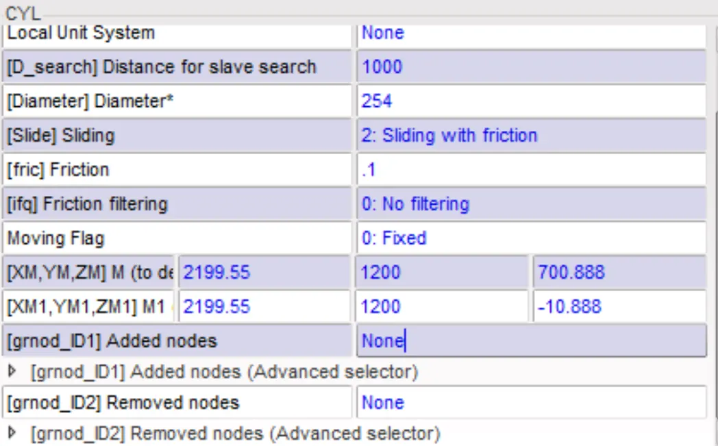
2) Rigid wall setup:

3) Defining additional masses for targe weight of 700 kg and balancing C.O.G requirements:
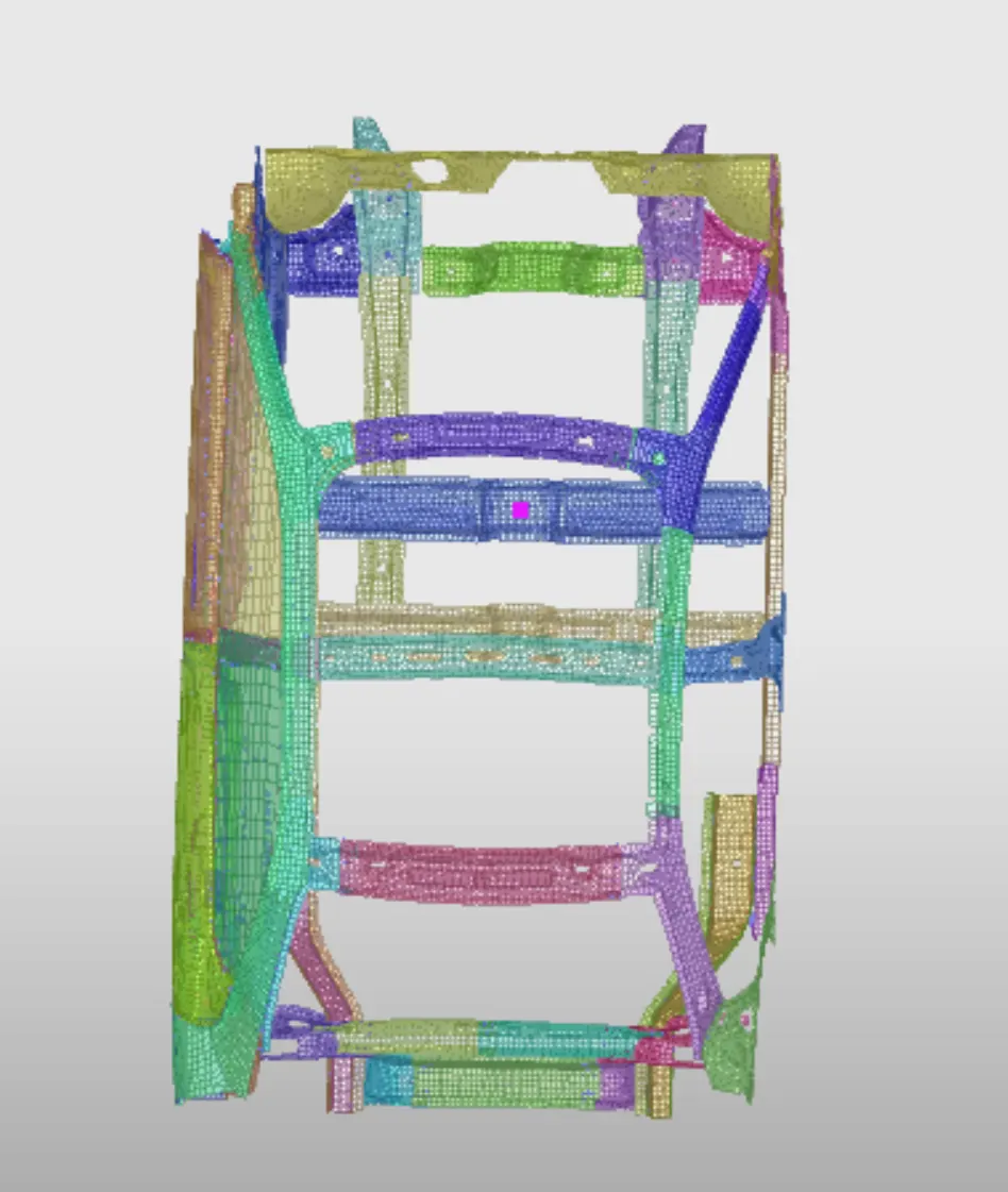
The target weight of the model is 700 kg and the optimum C.O.G location is between the driver and passenger seats.
Mass is added to the nodes outlined in red. A mass of 512 is added to those nodes. This brings out the C.G to the required position.
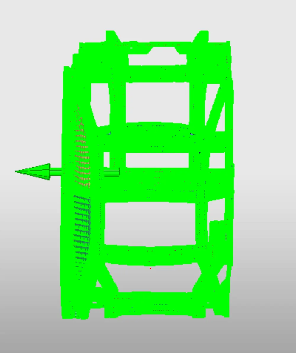
4) Defining initial velocity:
An initial velocity of 15.646 mm/ms is defined.
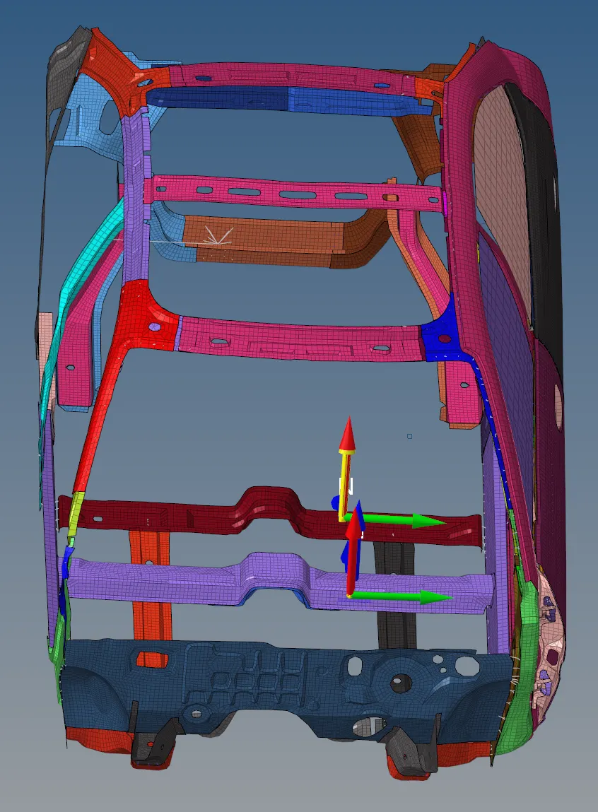
5) Defining cross-sections to measure sectional forces:
The output of the cross-sectional members has been requested.
These cross-sections have been highlighted in the figure below:
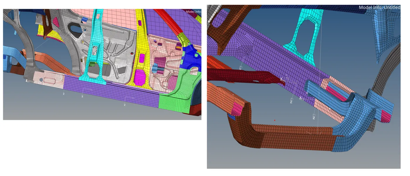
7) Intrusions:
For intrusions on hinge pillar, B-pillar base, and fuel tank, 3 moving skews have been defined.
8) Peak velocity:
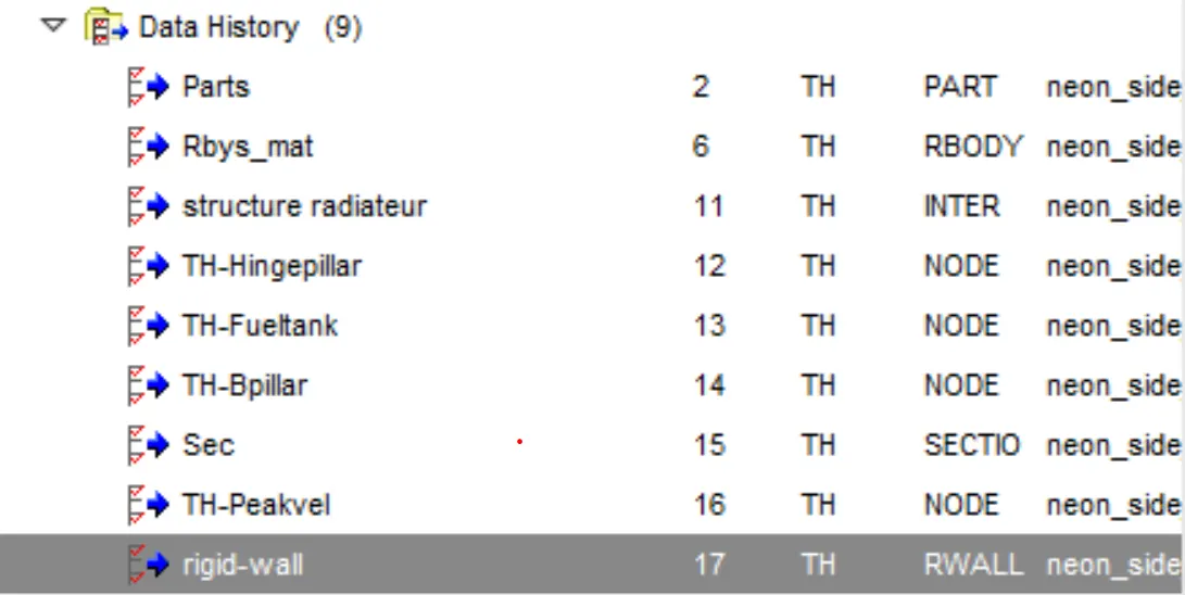
To measure the peak velocity of the required node, a separate TIME HISTORY request was added.
9) Control card definitions and Time history cards:
As per the given guidelines, the run time and frequency for animation files to be printed are already set as 80 and 0.5 respectively. This is not changed.
Another control card: ANIM/VECT is defined to animate displacement, stresses while post-processing:

Likewise, the time history card has been setup for the created sections and brake pedal nodes.
10) Model checker:
HyperCrash model checker is used to check for errors and warnings in the model.
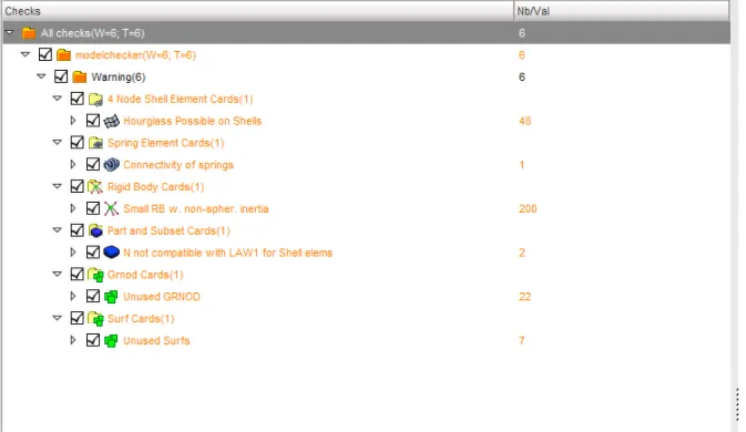
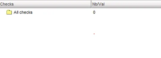
Around 6 warnings were present in the system. After the warnings are resolved, the model checker is run again.
Results:
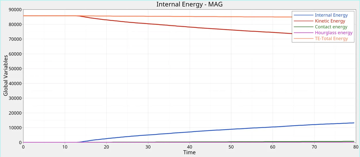
From the output file, a maximum of -0.9% energy error was present in the system.
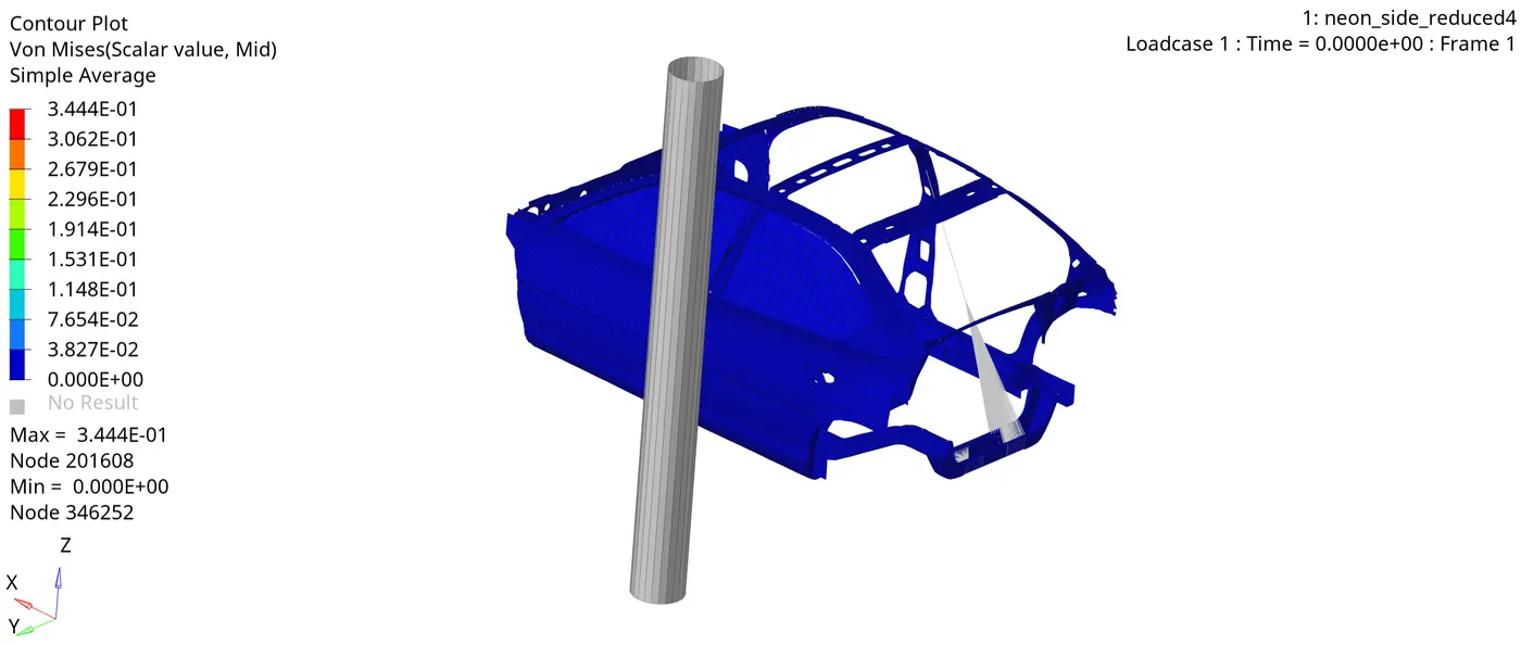
Von-Mises stress:
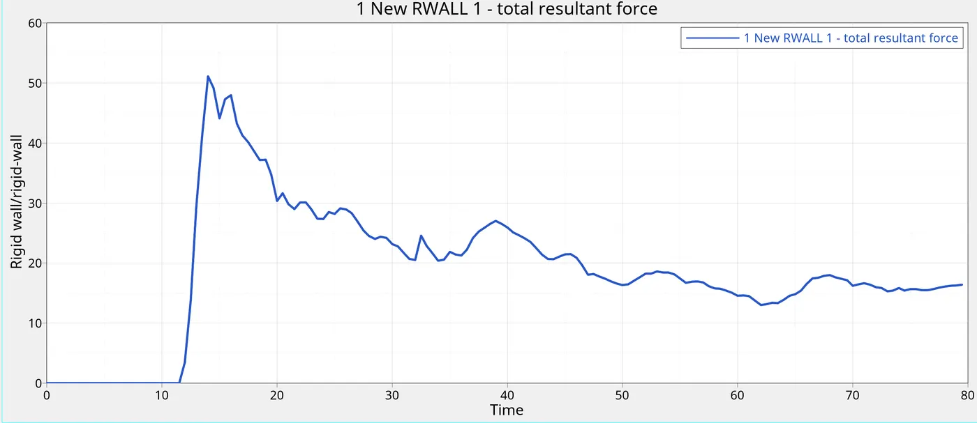
Rigid-wall forces vs Time
Energy Plots vs time:
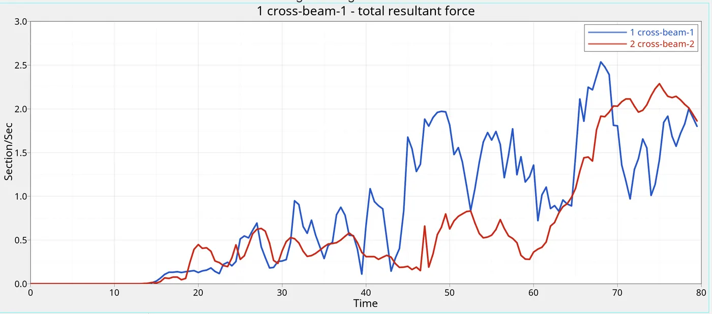
Sectional forces on the cross-members
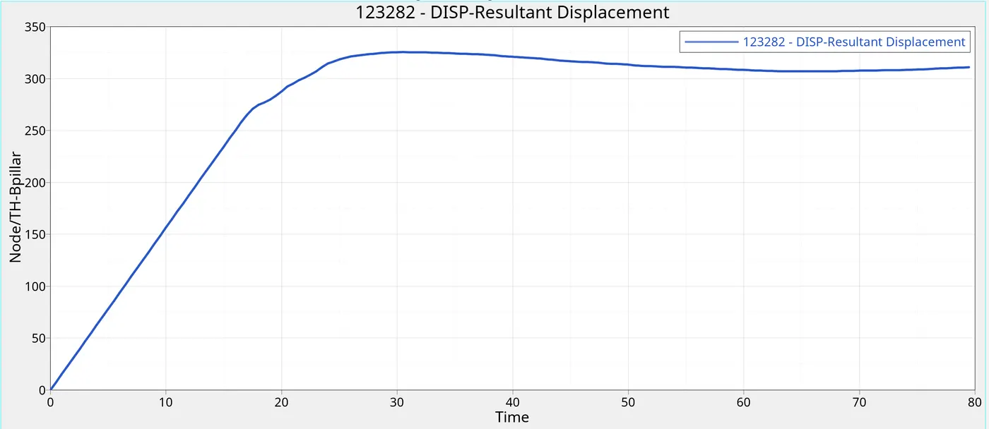
B-pillar Intrusion:
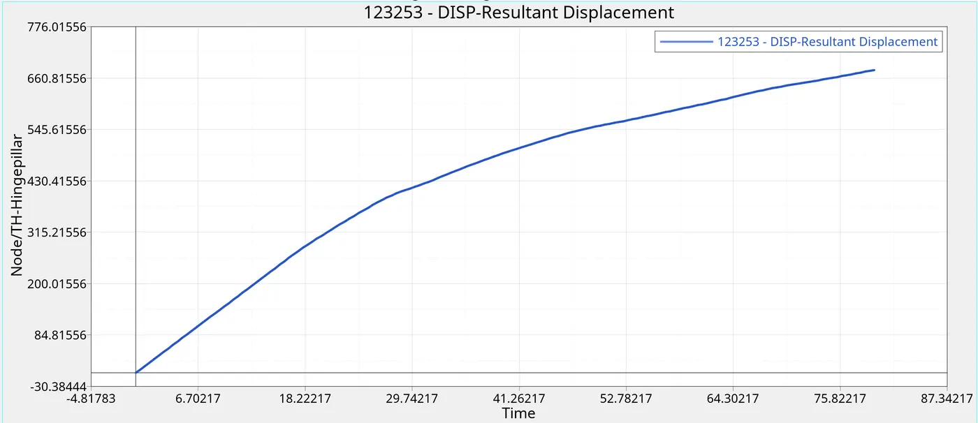
Hinge pillar intrusion:
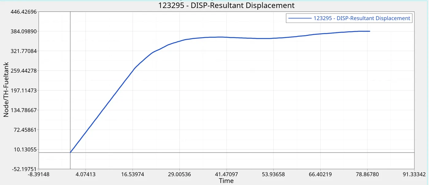
Fuel tank intrusion:
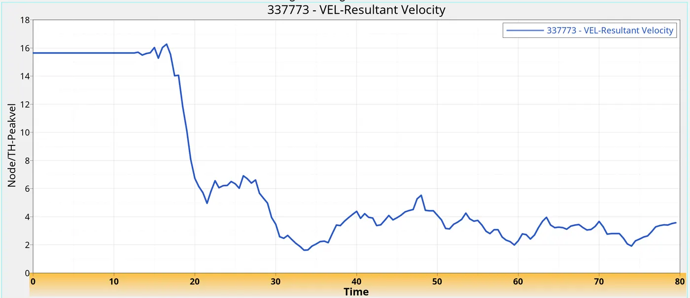
Peak velocity on the inner door:
Inferences:
|
Rigid wall forces vs time |
|
This graph is not as significant for the current simulation. However, the forces on the rigid wall keep on increasing till a point. This point is when the major impact happens and the car crashed into the rigid wall entirely. |
|
Energy plots |
|
The total energy of the system remains constant as can be seen. However, not all kinetic energy is converted into internal energy which suggests that the crash time should be over 80 ms. Hourglass energy of the simulation is almost zero. |
|
Sectional force on the Lower cross member |
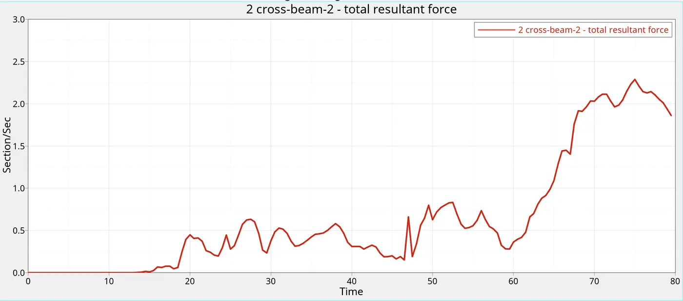 |
The sectional force reaches a peak a while after impact and gradually reduces. A small increase is seen towards the end due to self contact |
|
Sectional Forces on the Upper Cross-member |
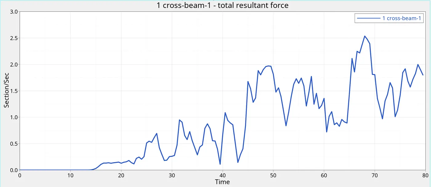 |
The sectional forces of the upper cross increase and reaches the peak before the lower cross member and reduces after that. A small increase is seen towards the end due to self contact |
|
Peak velocity on the inner door |
|
The node moves with a given initial velocity of 15.646 mm/ms until the impact. At the moment of impact, the velocity increases and reaches a peak, and then as kinetic energy comes down, the velocity drops considerably. |
| B-pillar intrusion | |
The intrusions on the B-pillar are found to be lower than other intrusions. |
| Hinge-pillar intrusion | |
|
| Fuel tank intrusion | |
Conclusion:
Hence, the side crash analysis of Dodge Neon is conducted as per given guidelines.