Side Pole Impact Analysis of NEON Doge Model in FMVSS Regulation
AIM :
To perform Car side crash analysis on the given BIW component by creating deck setup with the following objectives given below in hypermesh/hypercrash and request for time history plots to study the BIW model behaviour after crash simulation.
OBJECTIVE:
Neon side crash -BIW
- Check unit system and either follow [Mg mm s] or [Kg mm ms].
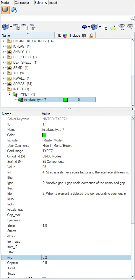
- Create appropriate interface ,friction 0.2 and recommended parameters.
- Make sure of no penetration and intersections.
- Create rigid wall with friction 0.1 as per referance model.
- Compare the model weight with the referance model and use added masses to reach target weight 700kg while getting CG about the required range.
- Initial velocity as shown in picture.
- Use model checker to ensure good quality.
- Timestep :0.5 to 0.1 microseconds.
- Run 80ms.
Note : Due to the limitations to the usage of no.of nodes in the student version we import the reduced model instead of full body by removing some components.so result may not be considering for real life senarios.
PROCEDURE :
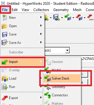
- Importing the BIW model using solver desk in hyermesh
To import the given model we will select import solver deck in the import tab, then we will select the file we wish to import in this case we select neon_side_0000.rad file under RADIOSS block.after importing we can see the model appears in wireframe mode which we can turn it into shaded mode.
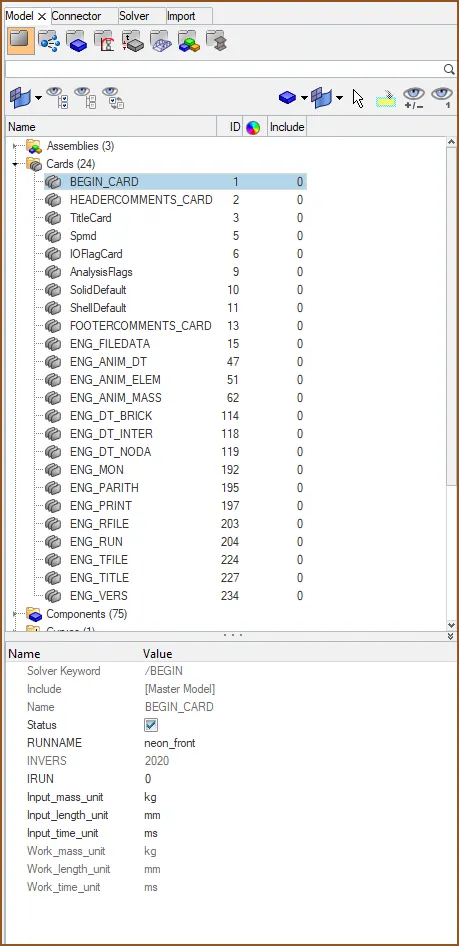
- Check unit system and either follow[Mg mm s] or [Kg mm ms].
we can assign all the boundary conditions,sections,masses to the model in hypermesh/hypercrash.here we imported the model we got and found out that the unit system assigned to the model is in kg,mm,ms so we will keep it without making any changes to it and follow the same units through the simulation process.to cross-check we can open the input rad file in notepad to see the units system.

- Make sure of no penetrations and intersection.
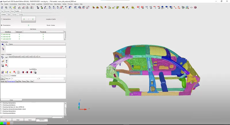
now the next step after importing the model is to check if there is any Penetrations and intersections that are presented in the model that should be removed from the model with Quality>Check All Solver Contact Interfaces in Hypercrash.
Initial mesh intersections create unrealistic connections. Moreover, this can cause locking situations leading to computation failure. Initial penetrations are due to the interface gap definition. They lead to unrealistic and uncontrolled internal forces which may cause local plastic strains in the beginning of the computation. The structure is then locally less stiff.
in the below image we can see that the contact tab shows there is no intersections and penetration present in the model.now we will proceed with assigning the initial velocity for the model.
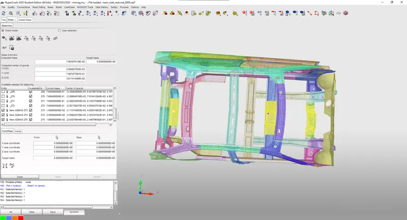
- Compare the model weight with the referance model and use added masses to reach target weight 700kg while getting CG about the required range.
since we reduced BIW frame which weighs of 189kgs to reduce computational time and cost, we need to add additional mass to the model give to us in order to make it a full scale model i.e., by making its total mass as 700kg through balancing the center of gravity,in this model we have to place ,masses in such a way that the CG point should lie in the middle.
- Initial velocity 35 mph.
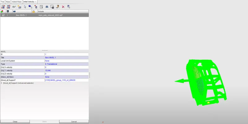
To create initial velocity we will select the load case tool and choose the initial velocity in that which will create a entity of initial velocity in the browser tab. by selecting the tab we can assign the numerical value of the velocity we need. in this we need a initial velocity of 35miles per hour. since our unit system is different, we cannot put the same value we need to convert that value into our required unit system i.e.,15.55 mm/ms.
after specifying the velocity in terms of mm and ms we need to assign this velocity to all the nodes that present in the car model for that we select all the nodes at once that present in the model and we specify the direction and translation to the nodes as shown in the below image.the arrow mark shows the direction of velocity in which the car body moves.
- Create rigid wall with friction 0.1 as per referance model
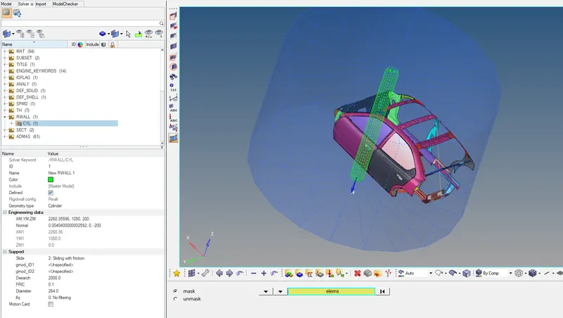
Now we will create the Rigid wall for the given Model with friction of 0.1 and Search Distance of 2000. to create Go to Solver Browser>Right Click>Create>RWALL then we Select the Type of rigid Wall.In this we have taken Cylindrical Rigid wall as we are simulating the vehicle for pole crash and enter the Coordinate of Nodes(M) where rigid wall to be created.later we will define the Node group defining slave nodes to be added to the rigid wall(grnd_ID1) and then we define the distance for slave search(D_search) and friction coefficiant as 0.1 and ao that we have created Rigid wall as shown below
- Create appropriate interface ,friction 0.2 and recommended parameters.
Interfaces are defined to model how parts interact when they come into contact with each other.In frontal impact test the car body is going to impact the rigid wall woth high velocity hat tends to crushing so we need to define suitable interface for slave and master nodes.in this case the rigid wall is considered master and the car component is considered to be slave and then while deforming the car component might come to self contact so we need to choose the elements and nodes of the car body as both master and slave and create a seperate interface,hence a multi-purpose contact (TYPE7) is defined in the model.Type 7 is a global contact interface which takes self contact or penetration of the BIW parts during impact with the rigid wall.
Interface TYPE7 is a multi-usage impact interface, modeling contact between a master surface and a group of slave nodes. It is also possible to consider heat transfer and heat friction.
- A node can at the same time be a slave and a master node.
- Each slave node can impact each master segment; except if it is connected to this segment.
- A node can impact on more than one segment.
- A node can impact on the two sides, on the edges and on the corners of each segments.
- It is a fast search algorithm without limitations.
- Time step is reduced in case of high impact speed or contacts with small gap.
- It does not work properly if used with a rigid body at high impact speed or rigid body with small gap.
- It does not solve edge to edge contact.
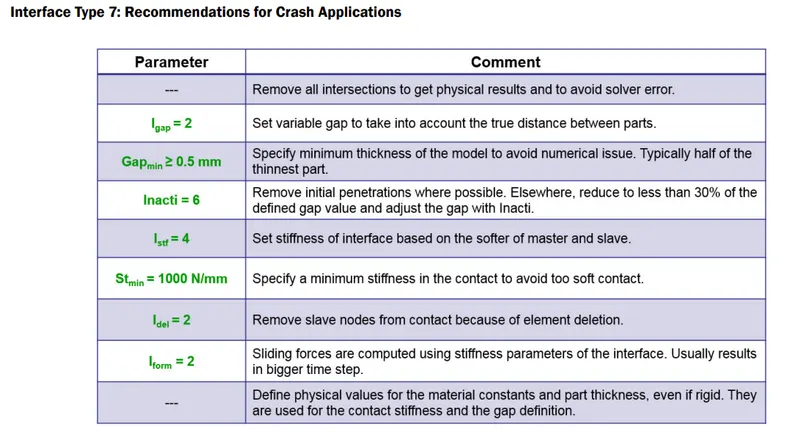
Parameters which control type 7 card
- Igap - determines how the size of the gap is calculated
-
Gapmin Minimum gap for impact activation - Inacti - Action to be taken if initial penetration exist
- Istif - affect how stiffness of the interface is calculated
- Iform - Friction formulation is of two types( Viscous and stiffness type) . The laer is used normally for structural analysis.
- Istif - The minimum stiffness is controled here
- Idel - If elements are attached to a deleted slave node this option specifies what is to be done to control it
- checking all the rigid body connections
Here we will check all the rigid body connections in the model by visual inspection by simply moving and panning ,rotating the model to check if all the surfaces and components are connected properly or not , Any two surfaces that have a gap between them must be connected using either Rigid Body connections or even springs in some cases.
In case we get two surfaces, where the contact is not appropriately defined, we then need to add a Rigid body Element or maybe a Spring Element.for now there is no changes were made in this challenge model since all the connection are seemed to be propely connected.
- create sections on the model to study the Sectional Forces
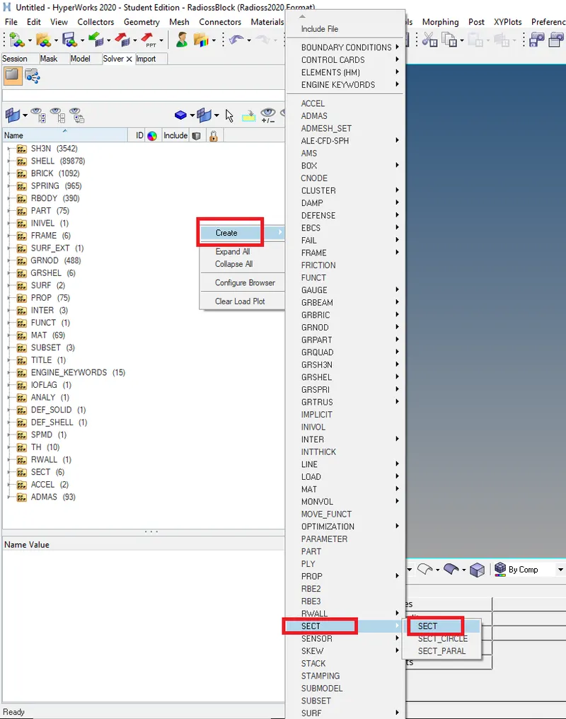
Before creating sections we need to create moving frame first,to create a moving frame we will right click on solver space and then we will select frame>move.
it will create a moving frame after that we will specify nodes that defines the origin by selecting it in the modeling window, or by entering the node ID and also the elements on which we need to make the section.
after specifying the nodes and elements we will now proceed with creating section,to create a section we will again right click on solver tab and then select the section from the menu.after creating a section we will assign the frame that we have created before.
We can clearly see that the Normals for all the Sections defined have a similar direction.
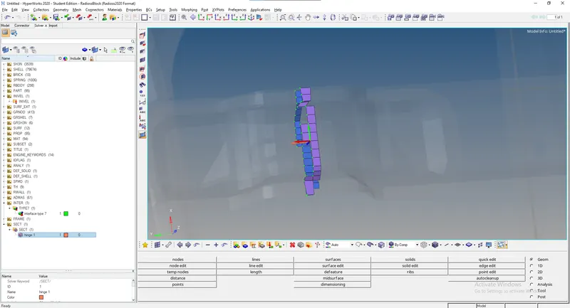
finally we made the sections in the model as per the challenge so that we can study the forces at those areas. below image shows that we have created two section on the cross-members.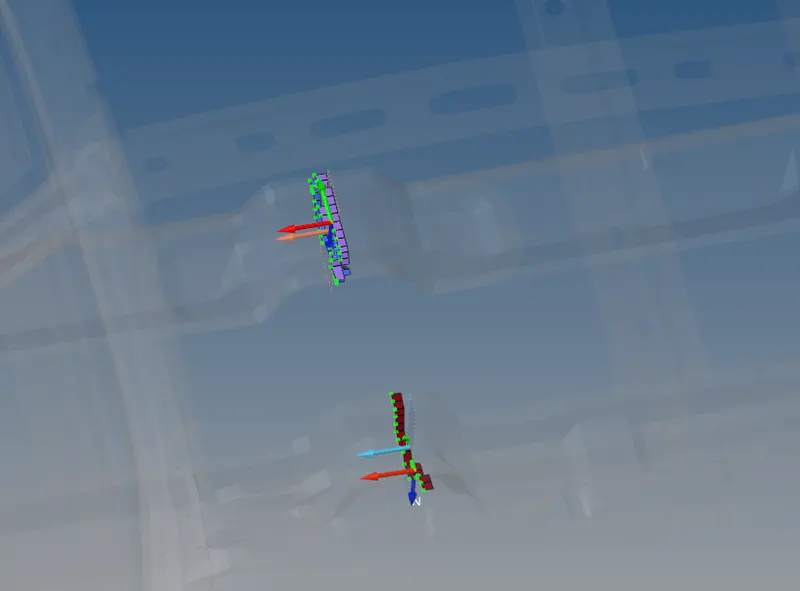
- Intrusion at B pillar,hinge pillar and fuel tank region.Provide recommendation on what can help to reduce Fuel tank intrusion.
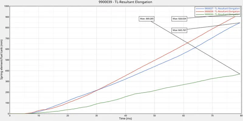
Now we have to measure the intrusions at B pillar, hinge pillar and the fuel tank region. In order to Check the Intrusion at those areas We have created Springs connecting the nodes on opposite sides of the vehicle by going to 1D>Springs>and we will select the nodes after that it will create a spring element and then we have applied Spring Properties
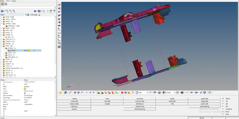
Peak velocity of inner node of the door.
After creating springs we will mark a temp node on the inner door of car and assign the TH for that node to find the peak velocity of the door.
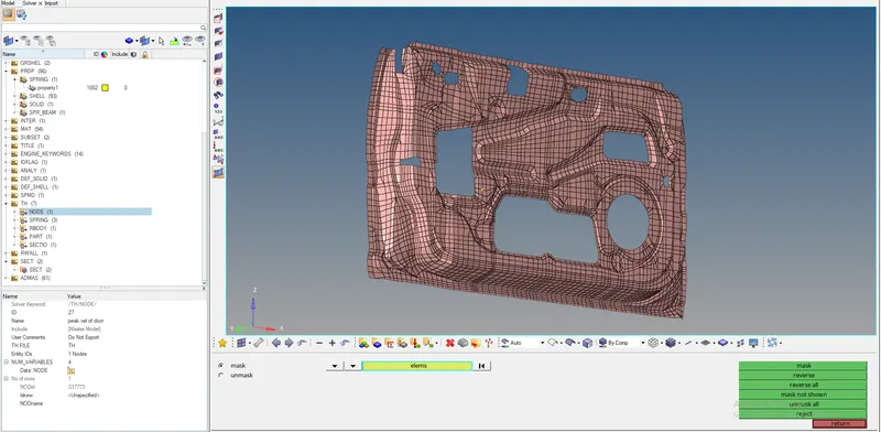
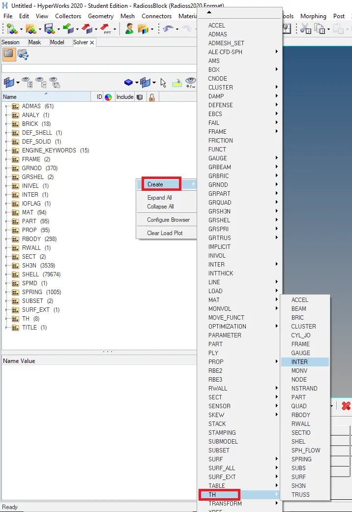
- TH request :
here we will create a time history output request i.e., we are going to request all required output which we need. To request Solver > Create > TH > select the type we need to record.
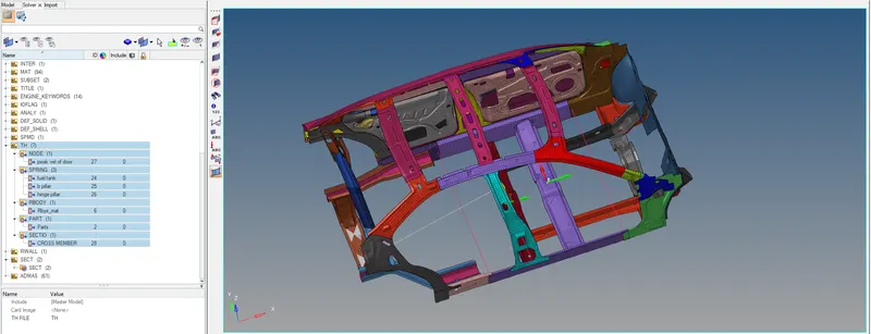
here we have requested TH for
- Sectional force in the cross member.
- Intrusion at B pillar,hinge pillar and fuel tank region.Provide recommendation on what can help to reduce Fuel tank intrusion.
- Peak velocity of inner node of the door.
After assigning all the required things we will check if there are any errors in the model in order to run the simulation smoothly
some of the functions of model checker all written below ;
- Model checker to exercises hundreds of unique checks, tracks model robustness for crash worthiness criteria, allows user-defined criteria checks
- Clean and simplify the model
- Check connectivity to identify unconnected parts, failed connection, for failed welds
- Check and automatically correct initial intersection/penetration
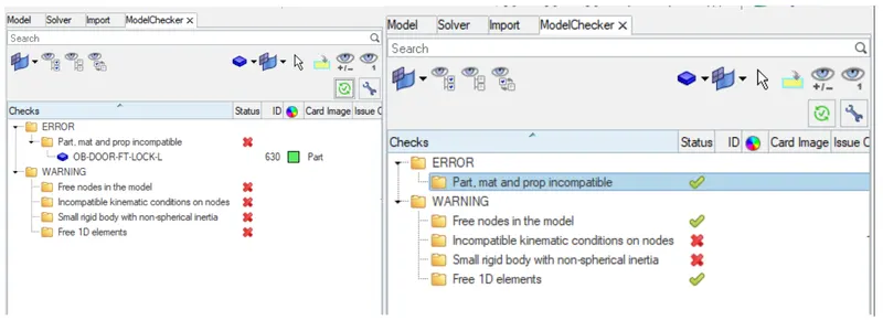
- Running model checker to ensure good quality
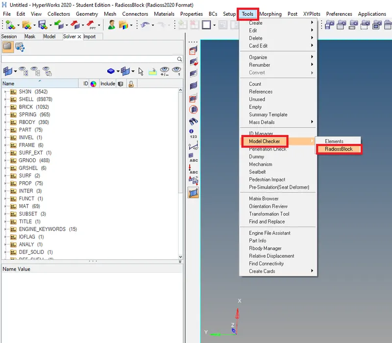
This model checker will show all the warnings and errors in the model. All the errors must be resolved and the warnings if not critical, can be left in the simulation, else, they too must be resolved. Like this the model can be checked and be resolved for any errors in the model.
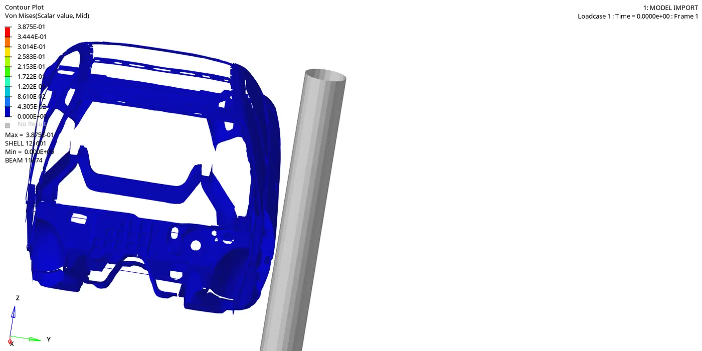
From the image below we see that Maximum Von Mises Stress : 0.98Gpa @ node 121601
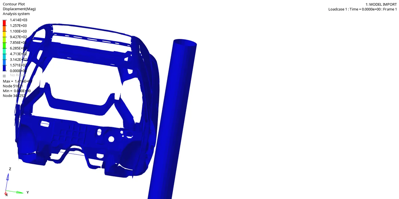
Maximum displacement of 1.414E+03 @ node 51621
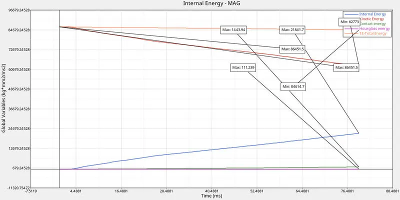
GRAPH PLOTS :
- Internal Energy, Kinetic Energy, Contact Energy,Hourglass energy and Total Energy:
- Peak velocity of inner node of the door
from the graph below we can see that the peak velocity is obtained at inner node is 15.98mm/ms at 5ms.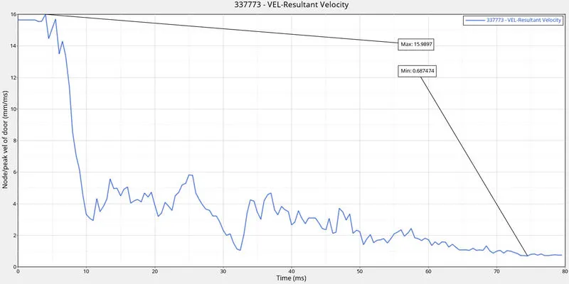
- Sectional forces in the cross members :
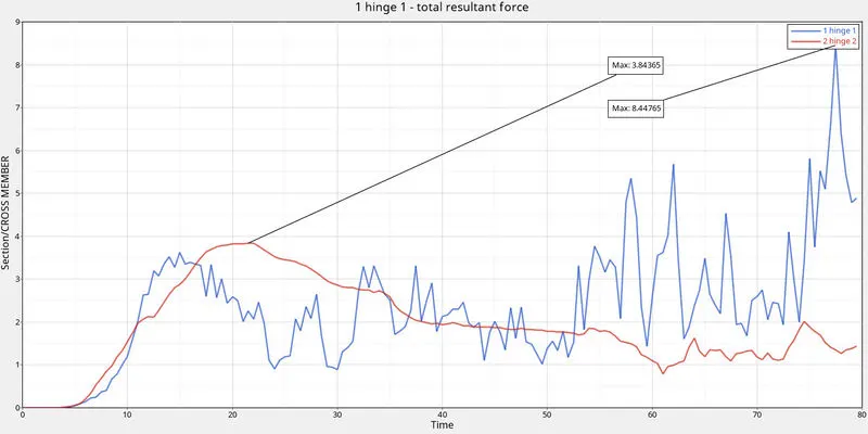
from the graph below we have observed that a maximum sectional force of 15.9897kN observed in the rear rail(*hinge1) whereas the maximum sectional force value of 3.84 isrecieved at fronr rail(*hinge 2).
- Intrusion/Displacement of nodes at B pillar,hinge pillar and fuel tank region:
ENERGY AND MASS ERROR :
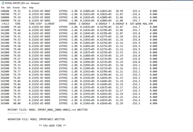
From the below Image we can see that the maximum Energy error is -1.8% (-ve due to energy dissipation because of hourglass or damping) and Mass Error is 0.00 which is Acceptable and the total number of cycles is 343400.
CONCLUSION :
- Finally, we can conclude that Car side crash analysis on the given BIW component was done by creating deck setup with the given objectives and recommended values and plotted the results as graphs by requesting TH for the cross-sections,intrusions and nodes.
- From the simulation, we understood how the crash happens and observed how the forces are transmitted along the sections form component to component.