Assignment 6-Frontal Crash Simulation Challenge
Objective
To perform the desired analysis of frontal crash on the car model using the appropriate settings given in the question and then plot the result contours and graphs for the desired output.
Frontal crash-BIW
- Check unit system and either follow[Mg mm s] or [Kg mm ms].
- Create appropriate interface ,friction 0.2 and recommended parameters.
- Make sure of no penetrations and intersection.
- Correct rigid bodies if any issues.
- Create rigid wall with friction 0.1.
- Compare the model weight with the full scale 300k nodes model and use added masses to reach target weight 700kg while getting CG about the required range.
- Initial velocity 35 mph.
- Use model checker to ensure good quality.
- Time-step :0.5 to 0.1 microseconds.
- Run 80 ms.
Output requests:
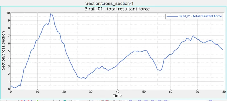
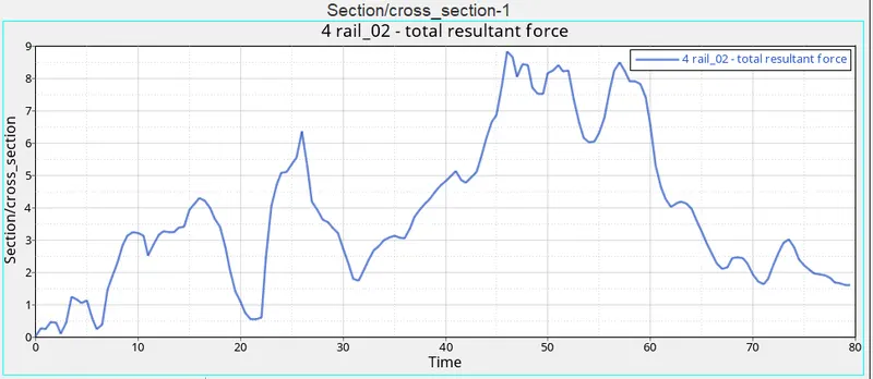
- Sectional force in the rails at location of indicated node 174247.
- Axial force received on the rails from bumper.
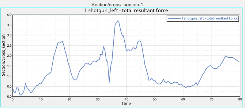
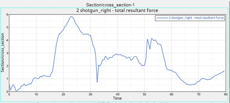
- Shotgun cross sectional forces.
- A pillar cross section.
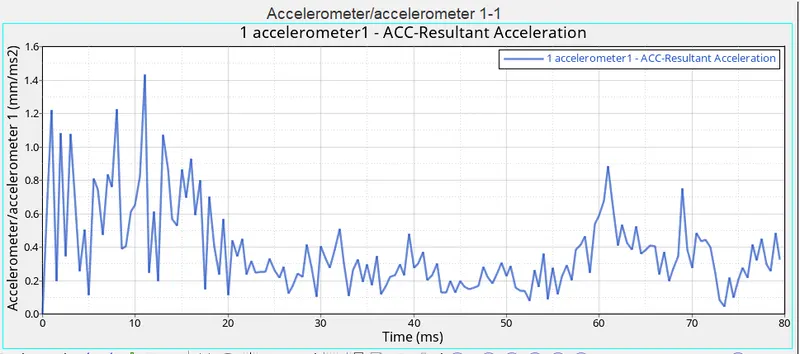
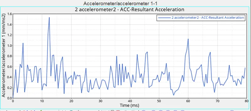
- Acceleration curve received on the accelerometer at base of B pillar (on B pillar rocker).
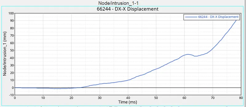
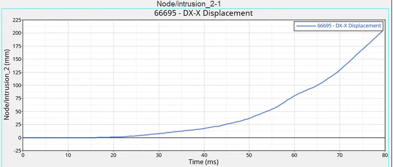
- Intrusions on the dash wall 66695,66244.
Procedure
Case setup and execution
- In the intial step the radios file is imported in the hypermesh window using the import option.
- Before importing the file in hypermesh open the .rad file in tex editor and check for the unit system , for this analysis we have used the kg mm ms unit system.
- Once the file is loaded in the hypermesh window , we need to open the model checker option and run the model checker for radios ,once the model checker run is completed we need to check for the any errors and if any error is found out we need to check it any emove it step by step.
- Now as per the details mentioned in the question we have to set the type 7 contact , for this we will create a group interface for all the assembly components and define all the neccesaary parameters and also assign the friction value as .2 as per the question.
- Then we need to check for the free components and penetration check , if there is any penetration available in the model then we have to go to translate panel and then move the nodes slowly to remove the penetration.
- Once these checks are done we will go to the model browser and then create the rigid wall will friction value of 0.1.
- After the rigid wall creation we can go to ANIM_DT card in the card section and define the time step as required.
- Once these steps are done we will create a set and try to balance the mass of the system to 700kg and at the same time try to bring the centre of gravity to the mid portion of assembly using ADMAS in the solver browser.
- Once the mass is balanced we setup the run time to 80 ms as per the instructions.
- After these steps we will setup the model for the output request we will create the the cross sextion at the required locations using SECTand FRAME options in the solver browser .
- Once the sections are created at all the 8 locations we will go to the output block in solver browser and create an output block for cross section and assign it to all the sections.
- After this we will again move to sover browser and create skew for the getting the intrusions at the pedal locations.
- Once the skew is created we will create the output block for both the intrusions and assignig the required node and skew to it at the same time.
- After creating the intrusion output we will create the acclerometer from the model browser , we will select the reqired nodes at the base of B pillar on both the sides and create 2 acclerometer.
- After this we will again go to output block and create the output for acclerometer.
- Once all the steps are done we will do the basic chekcs in the model for quality and then run the model checker for Radios once , the model checker should be free from errors before proceeding for the analysis.
- Once it is confirmed that model checker runs are ok and free from error we will move to analysis window and select the desired path to save and run the file.
- Once the simulation runs are done we will check the output file for mass error and energy error , it should be under the desired range.
- After cheking errors we will go to hyperview window and plot the required contours for stress, strain etc and graph for the sectional forces , accelerometer etc.
Images and Graphs
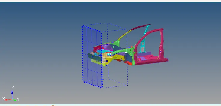
- Full assembly view of the meshed model along with the representation of rigid wall.
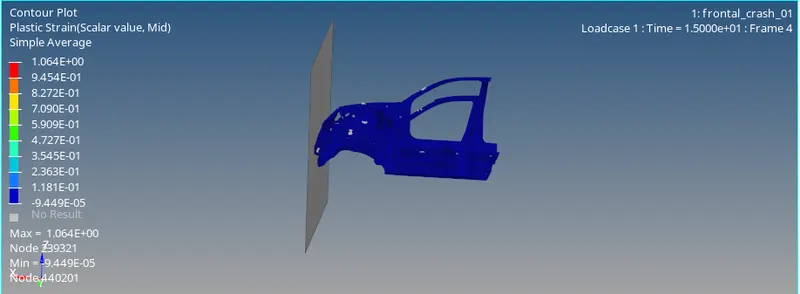
- Contour plot for the Plastic strain observed in model.
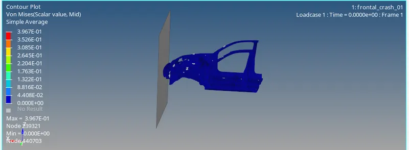
- Contour plot for the Von mises stress observed in model.
.
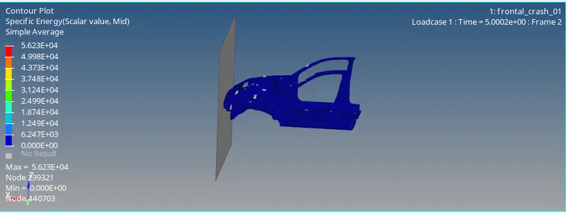
- Contour plot for the Specific Energy observed in model.
- Graph showing the intrusion at 66244 node location.
- Graph showing the intrusion at 66695 node location.
- Graph showing the accelerometer value at first location.
- Graph showing the accelerometer value at second location.
- Graph showing the Shotgun cross sectional forces at first location.
- Graph showing the Shotgun cross sectional forces at second location.
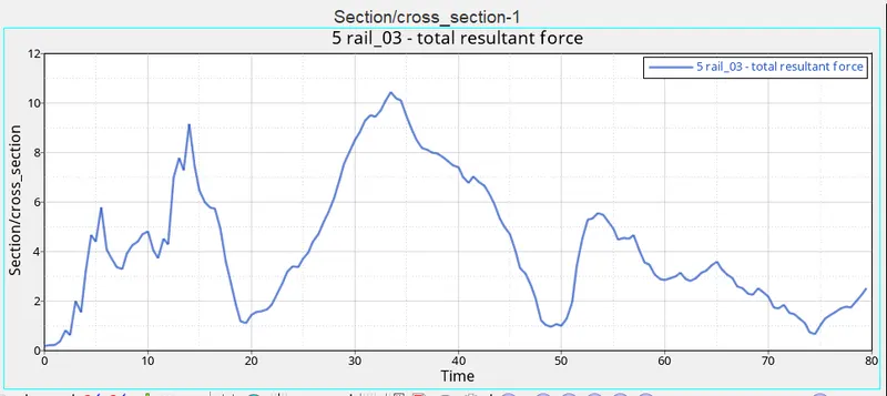
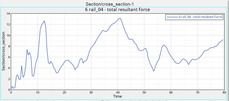
- Graph showing the Sectional force in the rails at first location.
- Graph showing the Sectional force in the rails at second location.
- Graph showing the Axial force received on the rails from bumper at first location.
- Graph showing the Axial force received on the rails from bumper at second location.
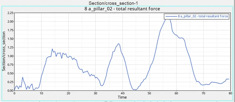
- Graph showing the A pillar cross section forces at first location.
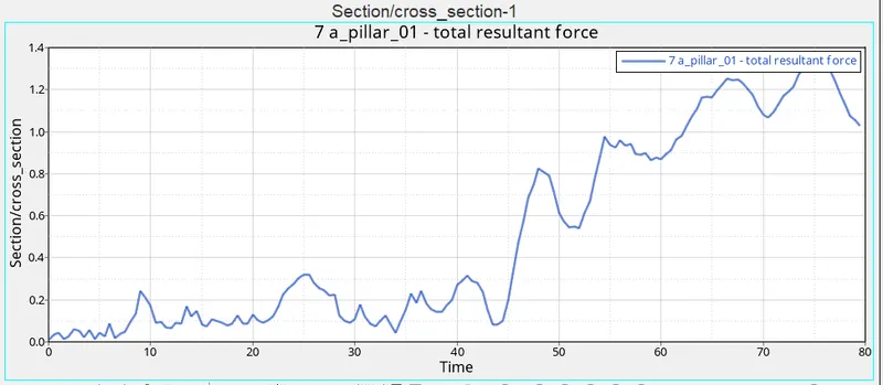
- Graph showing the A pillar cross section forces at second location.
Result
- From the simulation file it was observed that the mass and energy error are 0.00 % and -3.33% respectively in the model and these values are in the acceptable range for the simulation .
- The total time taken for the analysis was 19227.85s with toal number of the cycles of 305613.
- The max Von mises stress observed in model is 3.967e-1 kgmm-1ms-2
- The max Plastic Strain observed in model is 1.064
- The max Specific energy observed in model is 5.623e+4 kgmm2/ms2.
- All the graphs with the value of cross sectional forces on the four components in both left and right side are plotted.
- The graph for intrusion and accelerometer reading sa re also plotted as per the instructions.
Conclusion
Due to the limitation of the computation we have tried to mimic the full scale model with our current model with the copatibilty of the software version, for the same we tried to balance the mass of the assembly with a ful scale model of 700 kg.
As from the graph we can observe that at the cross sectional locations the forces observed are not equal , thus it can be cocluded that the model is not symmtrically stiff. as the value of sectional forces are not symmtrical.
Also during the entire simulation no major error or hourglassing is observed thus it can be concluded that the model result are satisfactory without any simulation error.
The process of this frontal crash simulation is of great importance as it plays a major role in defining the safety of the passenger as the most likely scenario of a car crash is frontal impact., from the simulation result it can be observed that the simulation performed is providing us with the satisfactory results as per our requirement.