Assignment 6-Frontal Crash Simulation Challenge
OBJECTIVE:
Frontal crash-BIW
- Check unit system and either follow[Mg mm s] or [Kg mm ms].
- Create appropriate interface ,friction 0.2 and recommended parameters.
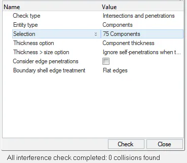
- Make sure of no penetrations and intersection.
- Correct rigid bodies if any issues.
- Create rigid wall with friction 0.1.
- Compare the model weight with the full scale 300k nodes model and use added masses to reach target weight 700kg while getting CG about the required range.
- Initial velocity 35 mph.
- Use model checker to ensure good quality.
- Time-step :0.5 to 0.1 microseconds.
- Run 80 ms.
Output requests:
- Sectional force in the rails at location of indicated node 174247.
- Axial force received on the rails from bumper.
- Shotgun cross sectional forces.
- A pillar cross section.
- Acceleration curve received on the accelerometer at base of B pillar (on B pillar rocker).
- Intrusions on the dash wall 66695,66244.
CASE SETUP:
First we will import the solver deck file neon_front_0000.rad in Radioss using Import
Solver Deck option.
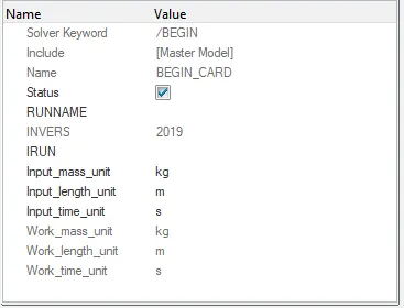
Check the unit system in BEGIN_CARD,here in this model the unit system is [kg mm ms].
Now we will check for penetration by using 'check penetrations' options in the Tools menu.
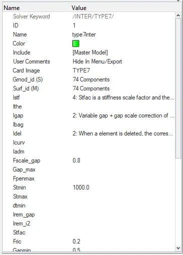
Now we will create interface 'interface' for this model, we will create Type 7 interface for all the components of the model as it is self-impacting.
We will go to Solver browser and we delete all the pre-exiting group of interface.
We create a new interface by selecting all the nodes all components for Slave nodes (Grnod_id) and master nodes (Surf_id). Then we will define all the
recommended parameters for Type 7 interface Istf = 4, Igap = 2, Idel = 2, Fscale_gap = 0.8, Stmin = 1 kN, Fric = 0.2, Gapmin = 0.5, Iform = 2
Rigid Wall:
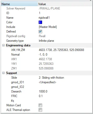
For creating rigid wall we will select the outer most node on the bumper and create a tempory node using 'temp node' option. Then we will right click in solver browser and go to Create > RWALL > PLANE.
We will givea gap of 10 mm in X direction as the wall should not be connected to the model.
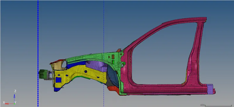
And then we will assign all the properties to the rigid wall.
Initial velocity:
In the solver browser go to Create > BOUNDARY CONDITIONS > INIVEL.
In INIVEL card, we will select all the components for grnd_ID. We will give the initial velocity of 35 mph or 15.6464 mm/ms in X-axis and mark the the velocity TRA that is translational.
Cross-sections:
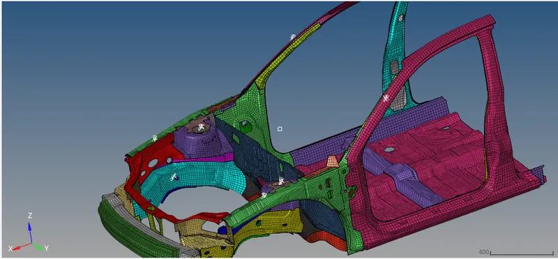
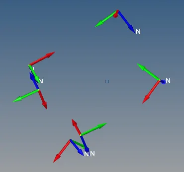
First we are going to create the moving frames on the points where cross-sectional force is asked to calculate. In order to create the frame we will go to create--> Frame--> Mov
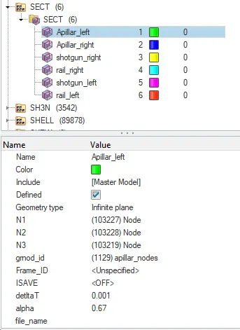
Now we wil create the sections so that we can check the forces on these points. To create the section we will go to the Create--> Sect--> Sect
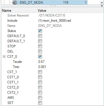
We are going to give the alpha value to be 0.67 and the delta T value to be 0.001.
Acceleration:
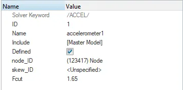
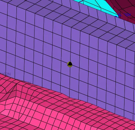
To create accelerometer, click in the Solver browser and navigate to Create > ACCEL. Then select the node on the B-pillar where we want acceleration result and specify F_cut value as 1.65.
Mass Balancing:
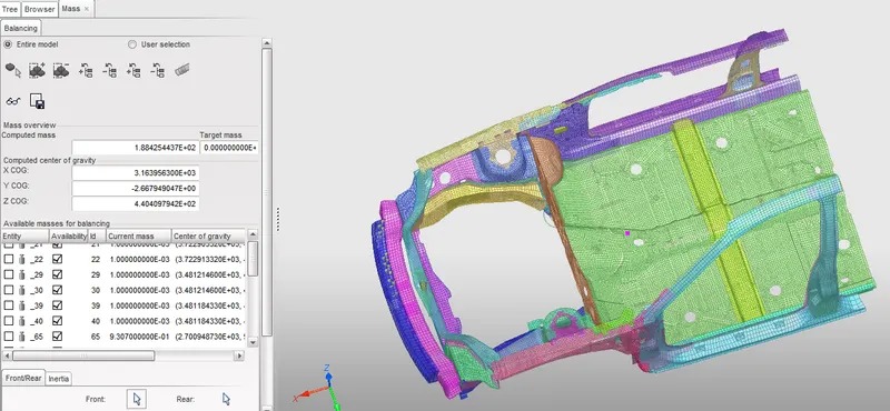
By checking the mass of existing model we can see that the mass of the vehicle is 188 kg and the CG of the vehicle is at the pink point.
We need to increase the mass of the vehicle to 700 Kg so we need to increase the mass of the model by keeping in mind the new CG location should come somewhere just behind the front row seats.
Now we will go to the solver browser we will right click and navigate to Create > ADMAS. In ADMAS panel, we will specify the required mass to selected nodes and for Mass type, we will select Mass/node option.
So we will create different weight at different locations similarly.
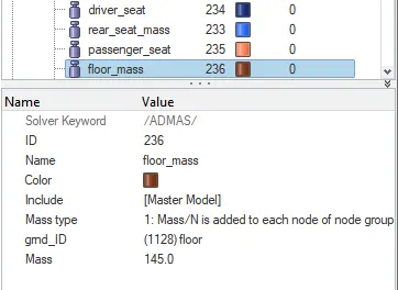
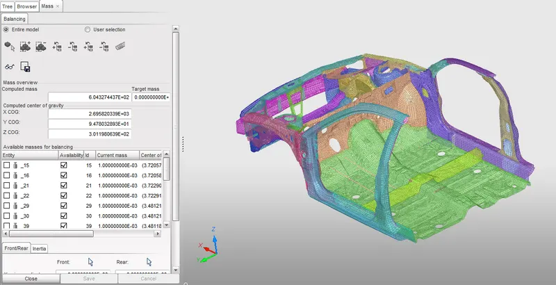
So we can see the Total mass of the vehicle as 600 kg.
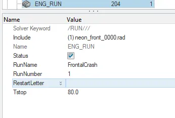
Time Step and Run time: For checking time step and and run time willwill go to Model browser and Open ENG_RUN card and ENG_DT_NODA
Model Checker –
To check the quality of the model,navigate to Tools > Model Checker > RadiossBlock.
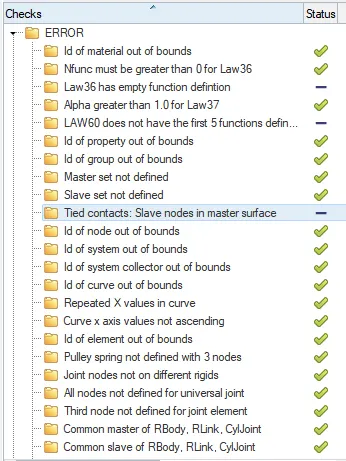
Run the model checker and in case of errors go for the Auto correct option.
Now go for to run the simulation. Navigate to Radioss in Analysis page. Save the model to a specified path and in options, type –nt 4 and click on Radioss to run the analysis.
SIMULATION AND RESULTS :
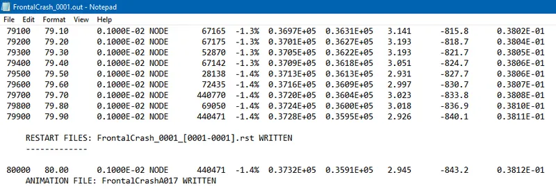
Check Energy error and Mass error, open the engine .out file of the model and check the last column for Energy and Mass error. Our Max Energy error comes out to be -1.4% which is acceptable. Total number of cycles are 80000 and time elapsed is 5534 sec.
For seeing results we will got to hypergraph.
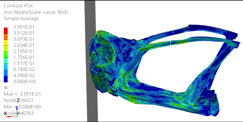
As this is reduced model we can see that the deformations are not realistic.
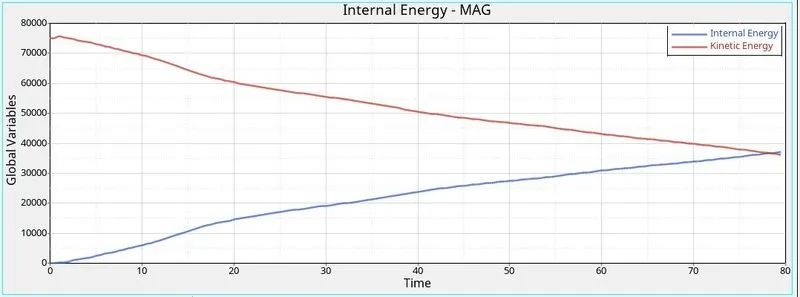
As the vehicle crashes and absorbs energy Kinetic energy starts to decrease and internal energy increaes.the energy error is very less so almost all the kinetic energy is getting converted to internal energy, moreover we have used QEPH elements so the Hourglass energy generated is almost zero.
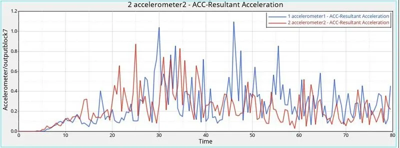
The acceleration readings on the left accelerometer is max 1.1 mm/ms^2 and on the right one is around 0.9 mm/ms^2 so the left B-pillar rocker experiences deformation faster as compared to the right B-pillar rocker.
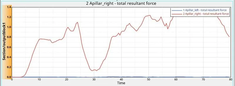
The resultant forces observed by the right A-pillar are much higher that the forces observed by the right A-pillar.
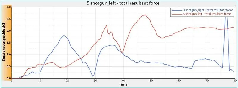
Initially the right shotgun experiences more forcs but as the time passes more forces are transmitted from the left shotgun.
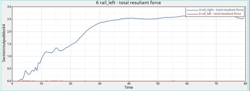
The right rail experiences most amount of forces as compared to the left rail.
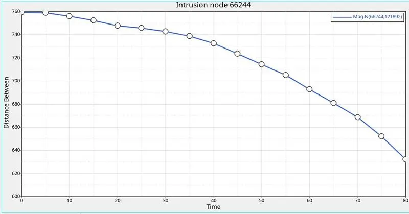
The intrusions measured by the spring on the node with ID 66244 is 760-630=130 mm
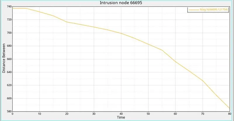
The intrusions measured by the spring on the node with ID 66695 is 738-685= 53 mm.
Conclusion: The model analysed is a reduced one so the the deformations are not realistic, also the model is getting rotated around the CG location so CG locations is also very important, We see that the forces experienced by thhe left half of the vehicle are some what less as compared to the right part, that can be due to uneven distribution of the load.