Assignment 6-Frontal Crash Simulation Challenge
Aim: Frontal Crash Simulation for given model and study of forces on various location and also study od intrusion to brake and accelerator pedal location .
Procedure:
Import the given model Using hypermesh>>radios solver >> import >>import solver deck>> select the path in file >> Import
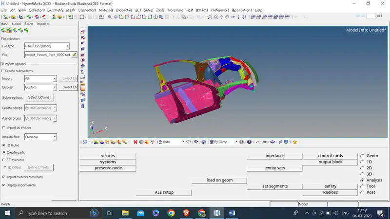
Task 1: Check unit system and either follow[Mg mm s] or [Kg mm ms].
Go to model>> card>> BEGIN_CARD
As checked we are following
Length: mm
Mass: Kg
Time : ms
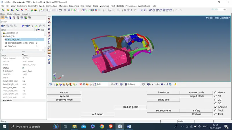
Task 2: Create appropriate interface ,friction 0.2 and recommended parameters.
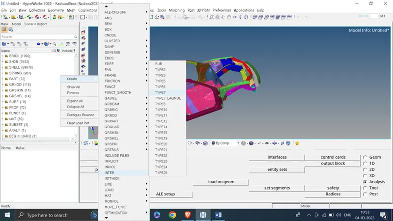
Right click on solver tab>>create > >inter>> type_7
Gmod_id (s): select all component (72)
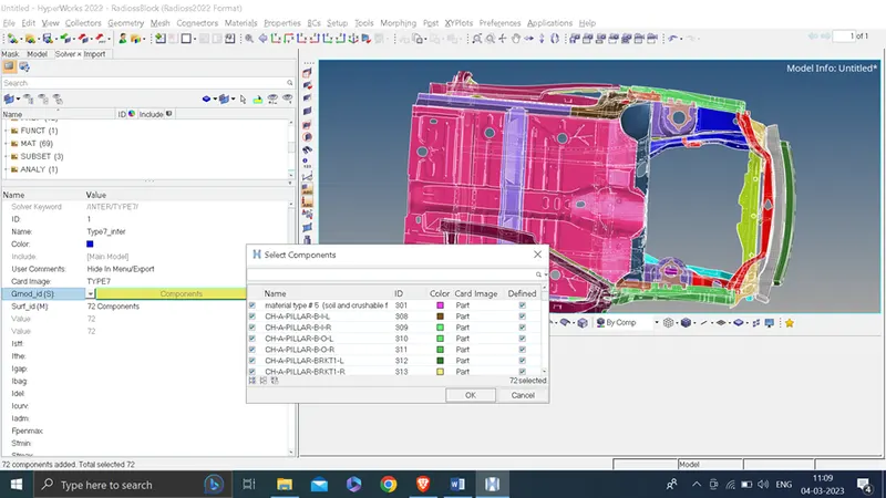
Surf_id (M): select all component (72)
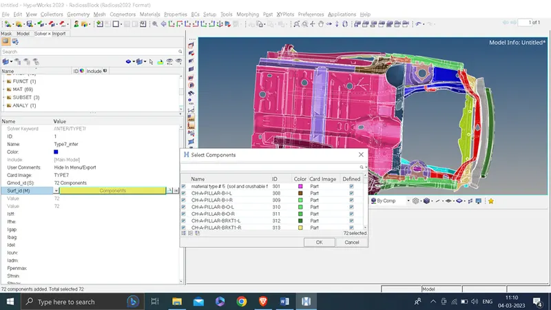
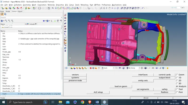
Istf: 4
Igap:2
Idel: 2
Fscale_gap :0.9
Stmin: 1
Fric: 0.2
Gapmin: 0.5
Task 3: Make sure of no penetrations and intersection.
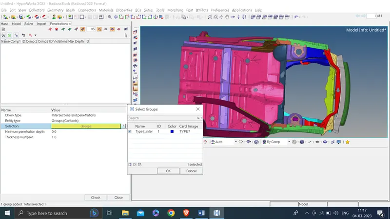
For this go to tool >> penetration check
Select type7_inter group
Click on check
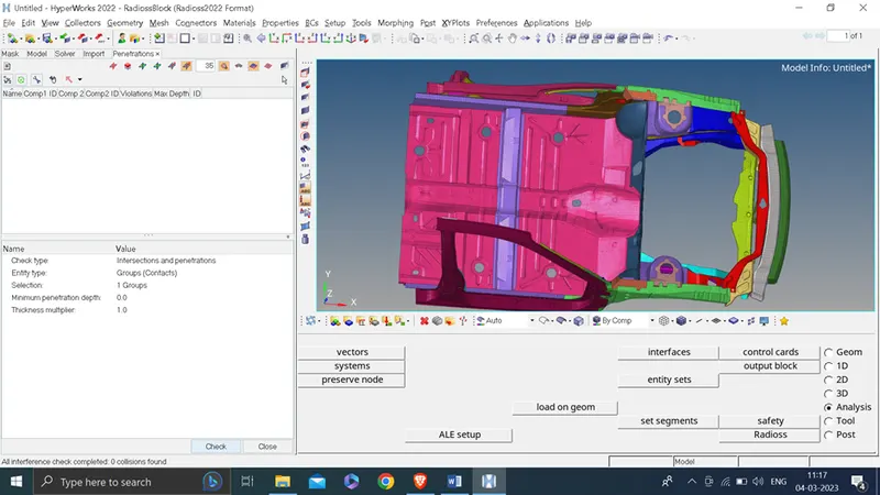
Thus we found zero intersection and penetration element
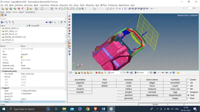
Task 5: Create rigid wall with friction 0.1.
For this we will 1st create outermost node to the front side of car and offset it with 50 mm
Geom>> temp node>> select node >> add
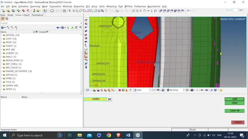
Now go to tool>>translate >> node >> select node and duplicate >> give direction as global X axis >> magnitude 50 >> click on translate two time so that node will translate 100 mm
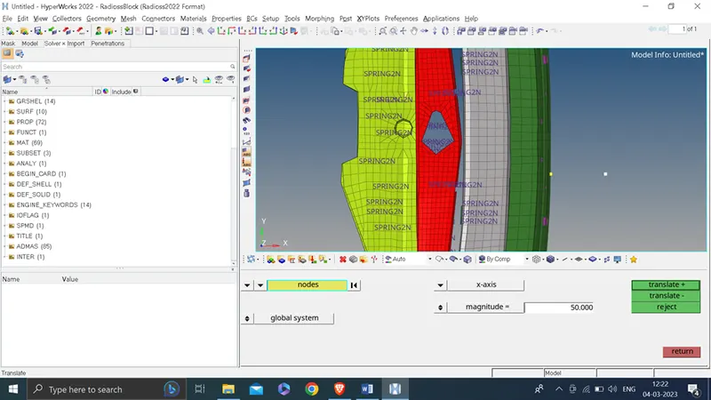
Now go to solver browser right click >> create >> Rwall>>plane
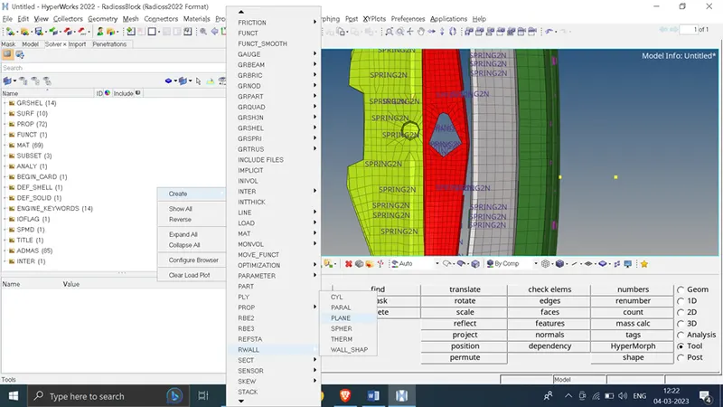
Set data as below
geometry wall : infinity wall
Engineering data : select node which created for rigid wall
Normal : -1 in x axis
Support:
Slide: 2 slide with friction
Dsearch : 2000
FRIC; 0.1
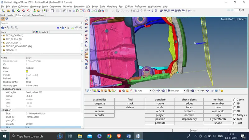
Rigid wall is create as shown below ‘
Task 6 : Compare the model weight with the full scale 300k nodes model and use added masses to reach target weight 700kg while getting CG about the required range.
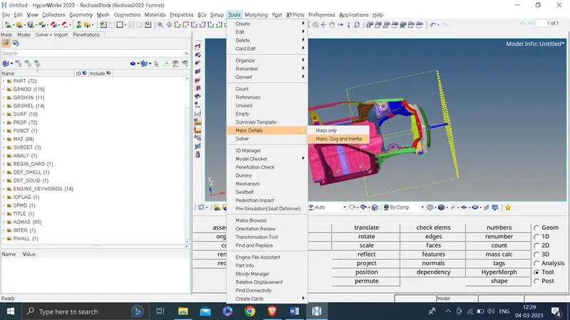
Now we will 1st check the total mass and COG of the vehicle
Tool>>mass details>> mass, cog and inertia
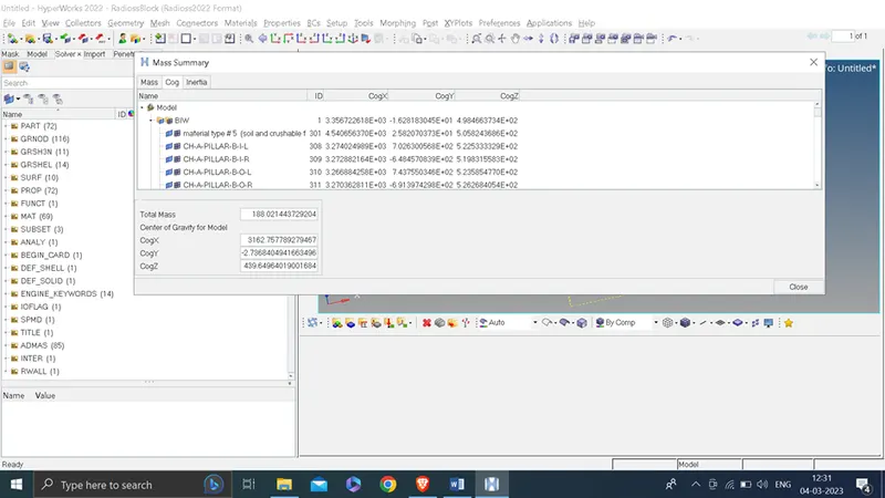
Total Mass: 188.021443729204
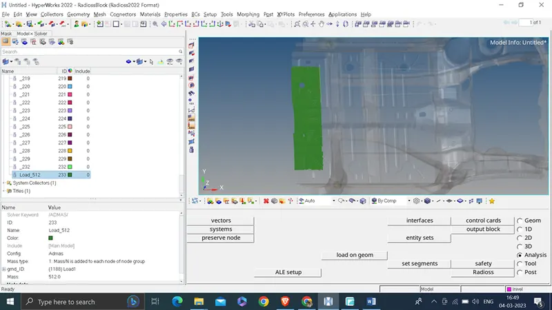
Required mass : 700 ; so we will add mass with magnitude of 512 kg
COG
To add mass
right click on solver browser >> create >> admas
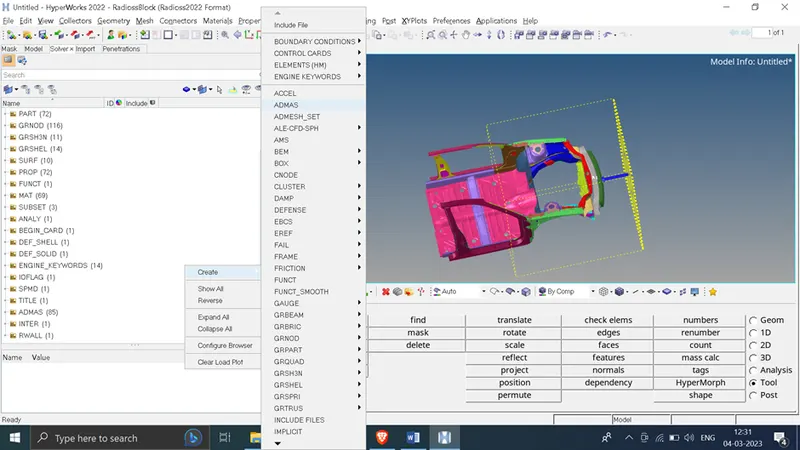
Mass type: 1 Mass/N is added to each node of the group
right click on Grnd_id: click on create /edit
Entity_id: select node as given below
Mass : 512
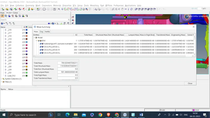
Now check again for mass and COG
Total mass is 700 kg
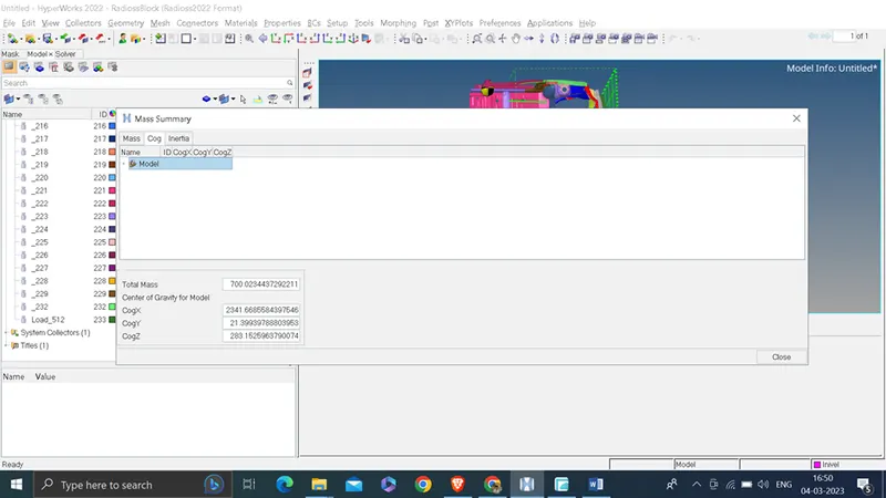
COG of vehicle
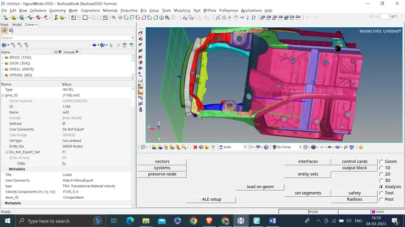
Task 7 : Initial velocity 35 mph.
To create initial velocity we will right click on solver >>create > > boundary condion >> INIVEL
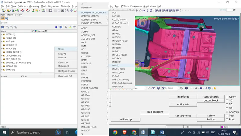
Convert 35 mph to mm/ms which is 15.65 mm/ms
Grnd_id : select all nodes of vehicle
Type: TRA Translational material velocity
velocity component : x-direction (15.65) ; y-0,z-0
Task 8: Use model checker to ensure good quality.
To perform model check
tool>>model checker >> radios block
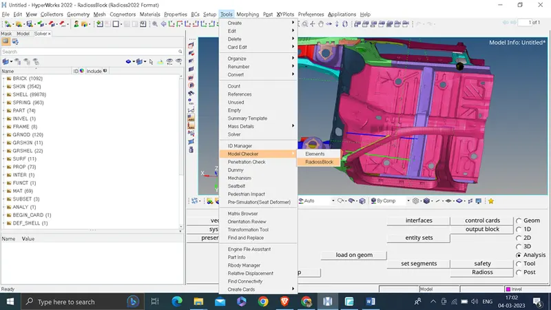
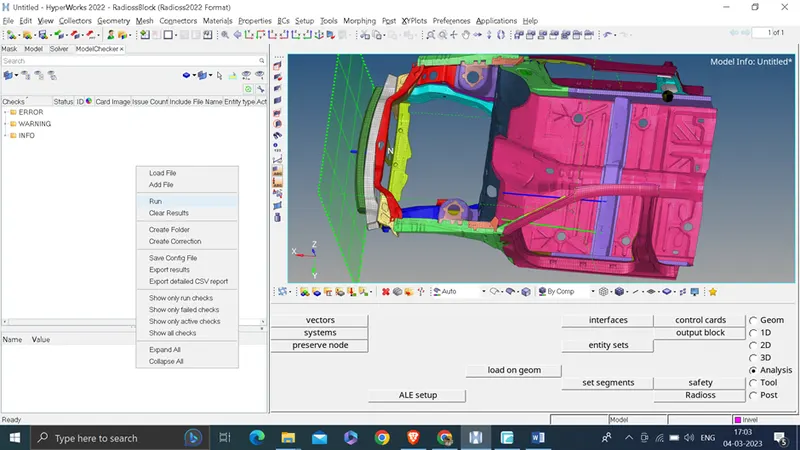
Right click on model checker and run
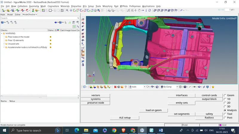
As we have run model checker and not found any error to solve , so we will proceed
Task 9: Time-step :0.5 to 0.1 microseconds.
To set this we will go to model browser >>Card>>ENG_ANIM_DT
Tfreq: 5 ms( this we will set to reduce simulation time)
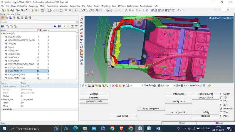
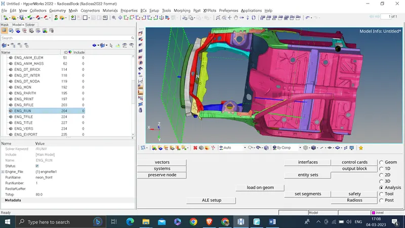
Task 10: Run for 80 ms
For this we will go to Model browser >> Card >> ENG_run
Tstop : 80
Task 11:
Output requests:
- Sectional force in the rails at location of indicated node 174247.
- Axial force received on the rails from bumper.
- Shotgun cross sectional forces.
- A pillar cross section.
- Acceleration curve received on the accelerometer at base of B pillar (on B pillar rocker).
- Intrusions on the dash wall 66695,66244.
Procedure: show a temp node for node id 174247
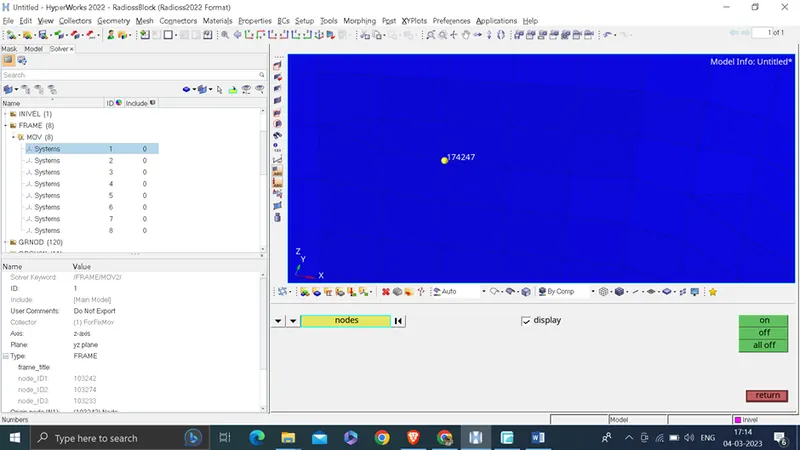
Now right click on solver browser >> create >> frame >> mov
Click origin as generated node , z axis and YZ plane node as shown below
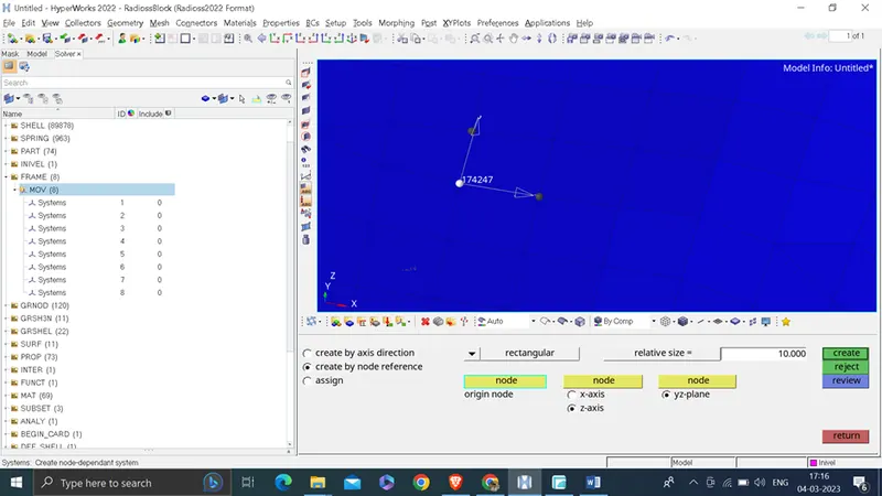
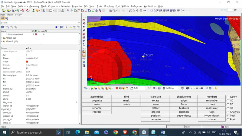
Now create section
To create section right click on solver browser >> create >> sect >> sect
Select N1, N2 and N3 as previous node which used to define the frame
Frame_Id: select 1 ( as we create frame have id 1)
DeltaT: 01.
Alpha: 0.628
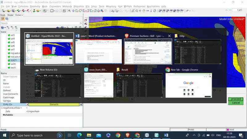
Gshell_id: right click and click on create/edit
And select elements as shown below
Now create Time history plot for output
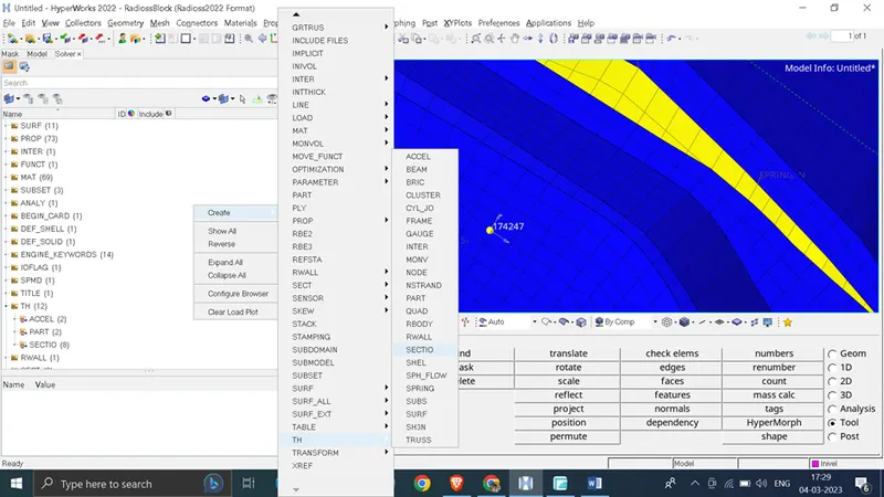
For that right click on solver browser >> create >> Th >>section
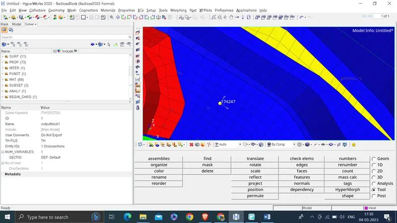
Enitiy IDs: select crosssection 1 ( which we created)
Num Varible : 1
Sectio: DEF
Now we will repeat same process for bumper , shotgun, A pillar on both side
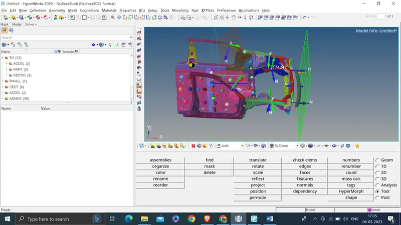
Now to create Acceleration curve received on the accelerometer at base of B pillar (on B pillar rocker).
We will create temp node on on below location ( below the B pillar)
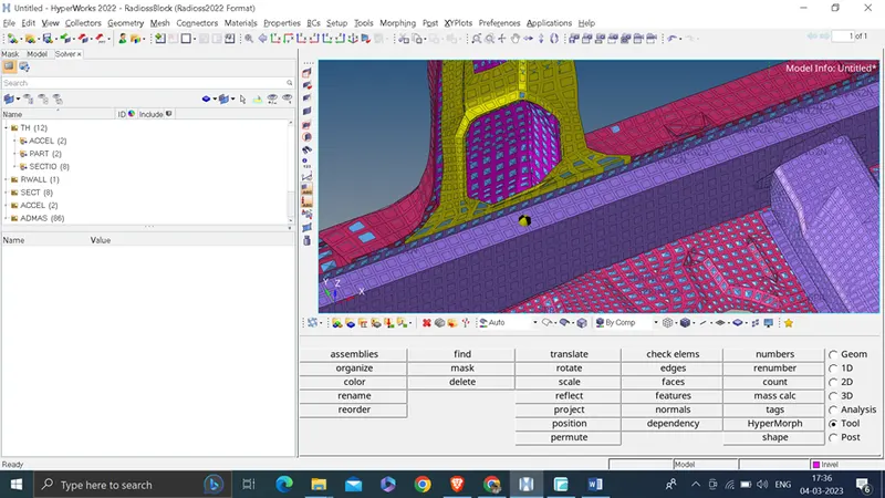
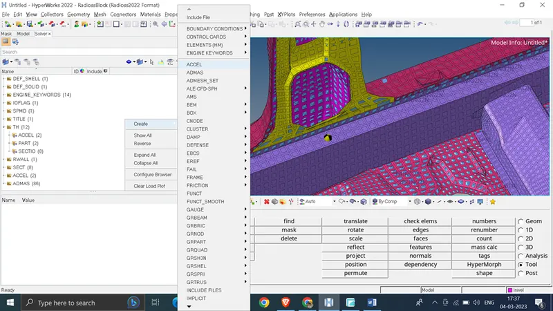
To create accelerometer right click on solver browser >> create >> accel
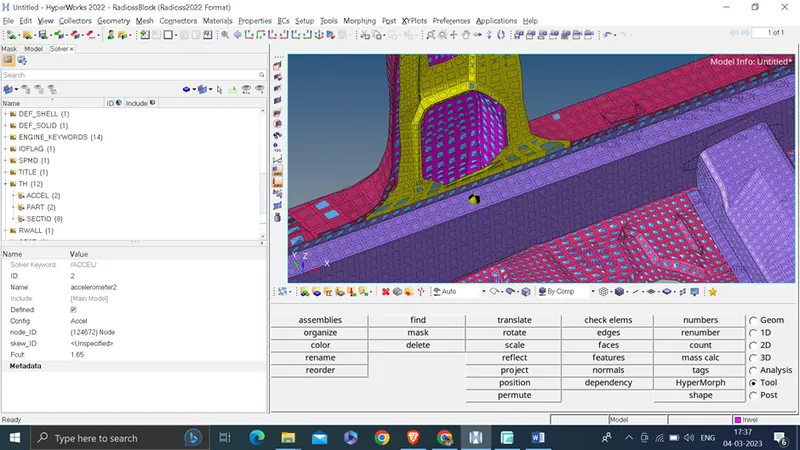
Node Id: select node
F_out: 1.65
Create Th out file
For that right click on solver browser >> create >> Th >> Accel
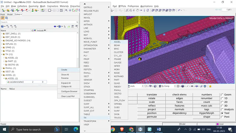
Entity Id : select accelerometer 1 ( which we created now )
Num_ Variable : 1
Accel :DEF
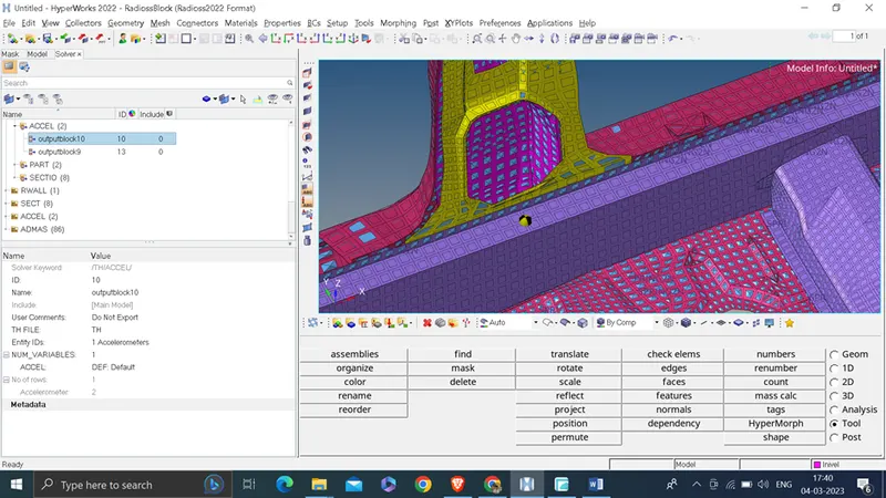
Create same for other opposite side
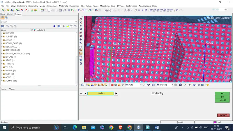
Now create Intrusions on the dash wall 66695,66244.
Now node visible for above node id
Now we will create two collector in model >> component to collect two weak spring with stiffness and mass minimum
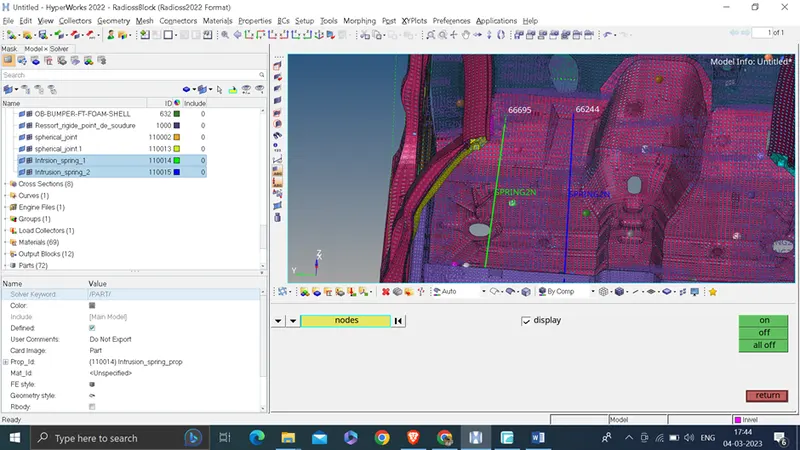
Create property for spring
Right click on model browser >> create >> material
Mass : 0.001
k1 : 0.001
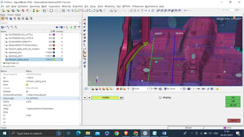
Assign this material to spring component
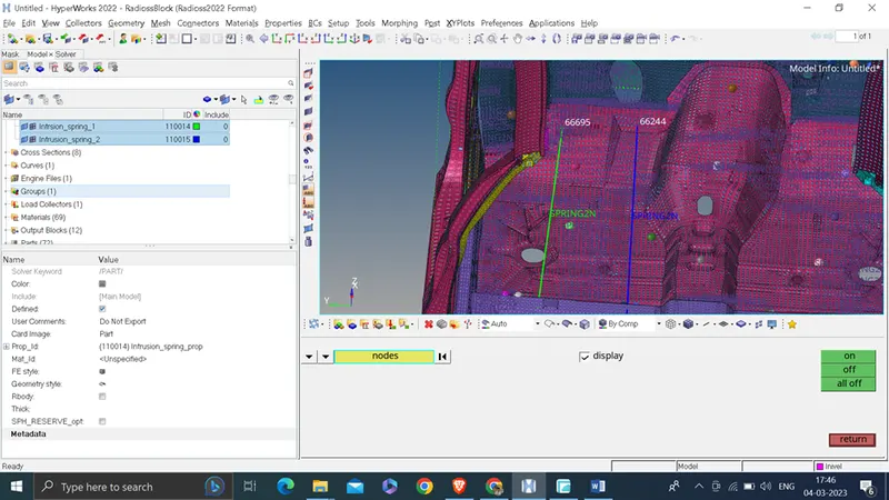
Now create 2 spring 1 in each collector as shown below
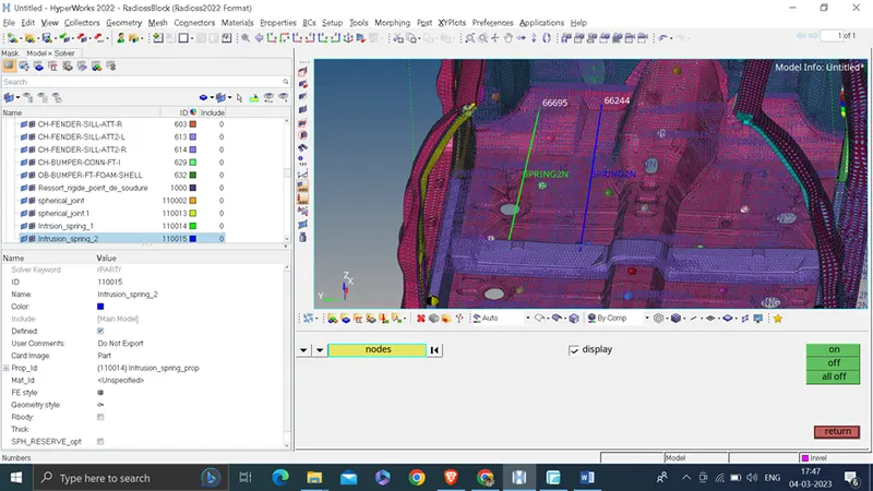
Now create time history plot for this spring
Right click on solver browser >> create >> Th >> Part
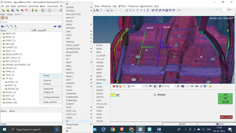
Entity id: select 1 component
Num_variable : 1
Part : DEF
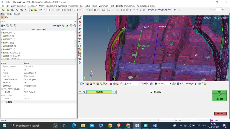
Create Th file for other component
Now export the model in required location ( select path )
export : all
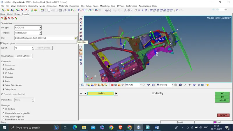
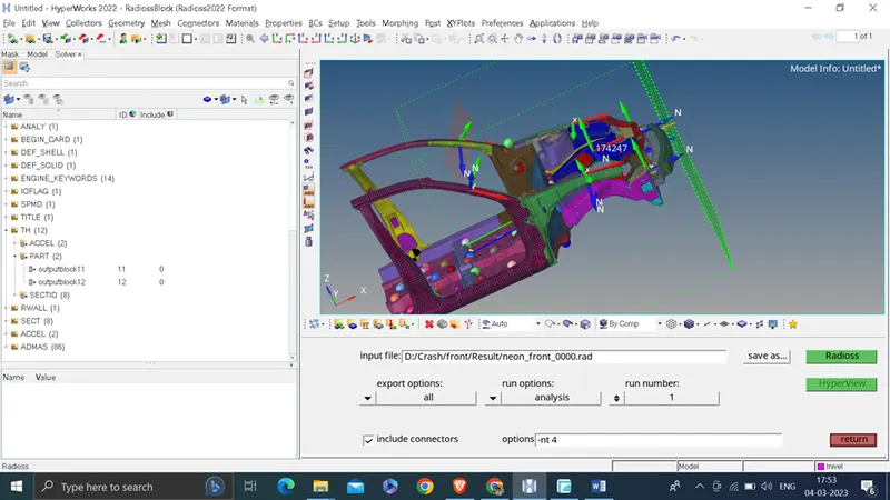
For run the simulation
go to analysis
Radioss
export option : all
Include Connector : checked
Option : -nt 4
click on radios
After simulation complete .
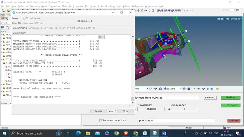
Time taken to run simulation: 1:06:03
Result :
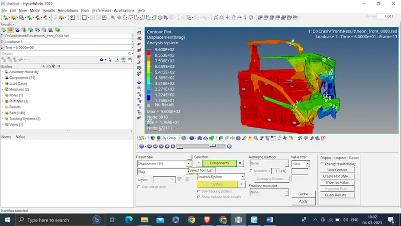
Displacement : Max displacement : 9.6E+2
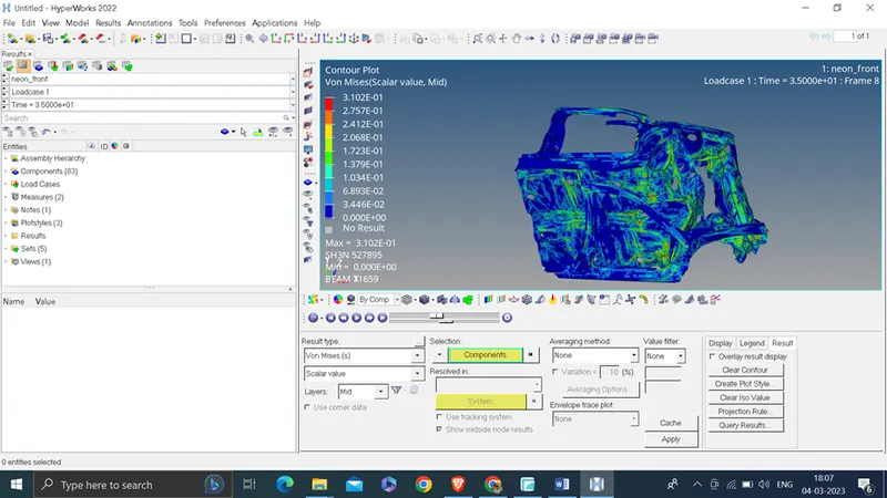
Von mises stress
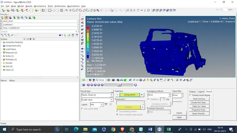
Plastic strain:
Energy Error : -1.7%
Mass Error : 0.2974E-01
Plot :
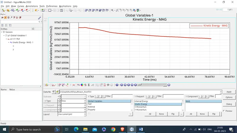
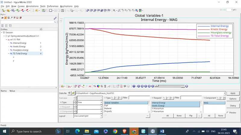
Internal Energy
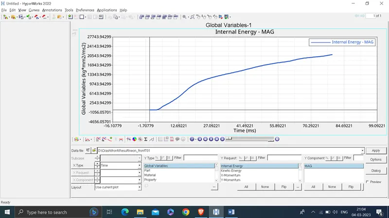
Kinetic Energy
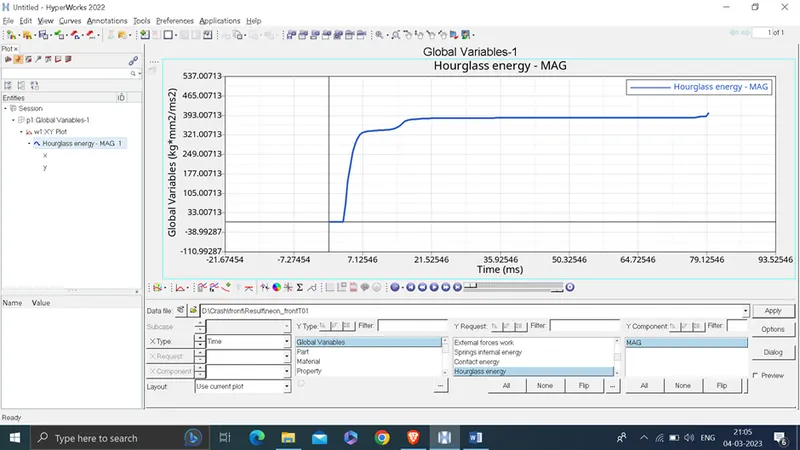
Hourglass energy
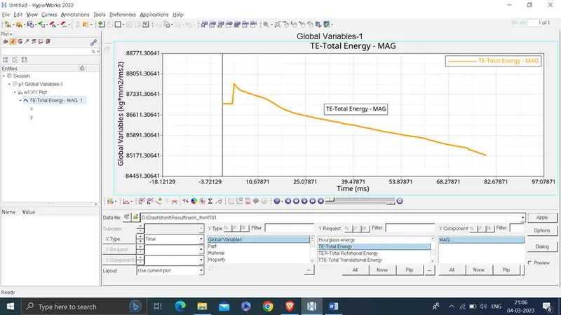
Total Energy
- A Pillar (Left ) cross sectional force
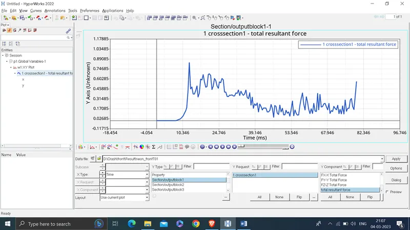
on the left A-Pillar the maximum resultant force experienced at cross section is 0.838 KN.
2.ShotGun (Left) Cross Sectional force
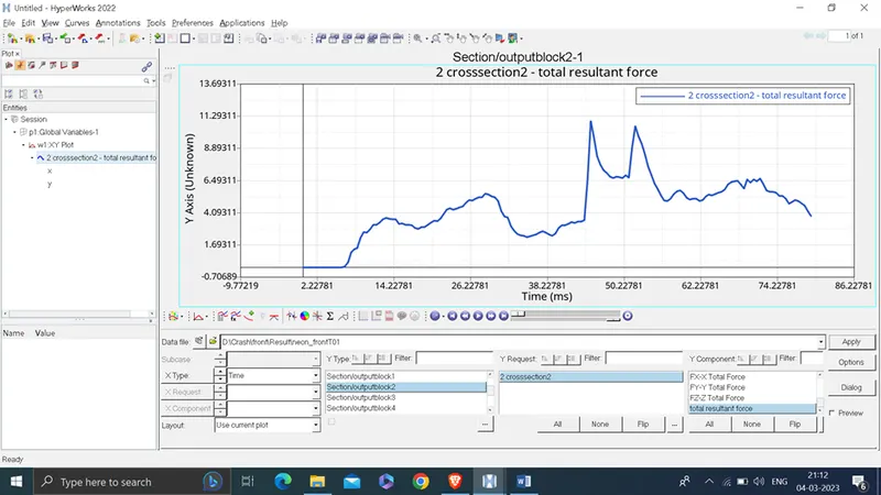
on the left shot gun the maximum resultant force experienced at cross section is 10.93 KN.
- ShotGun (Right ) Cross Sectional force
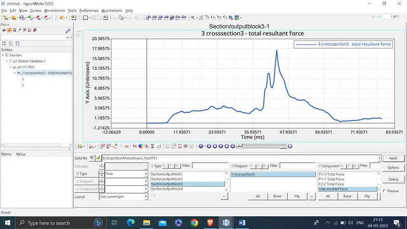
on the right shot gun the maximum resultant force experienced at cross section is 17.65 kN.
- A Pillar (Right ) cross sectional force.
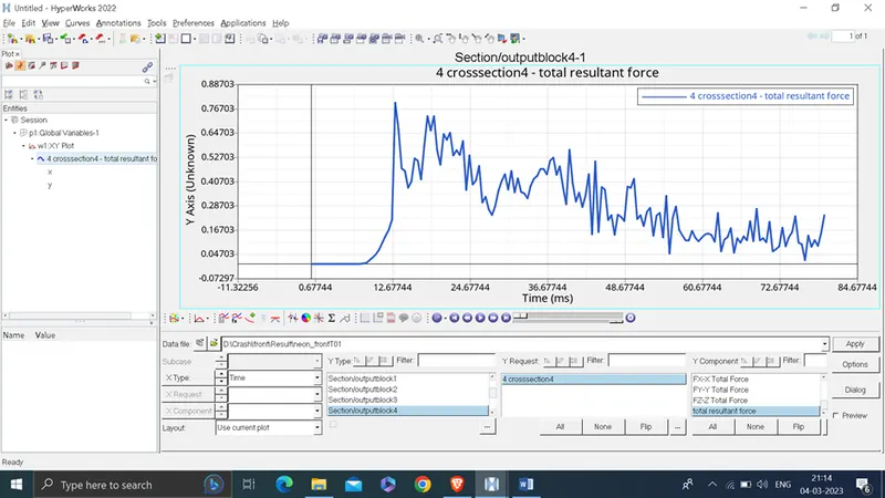
on the right A-Pillar the maximum resultant force experienced at cross section is 0.797 KN.
- Axial force received Bumper (left)
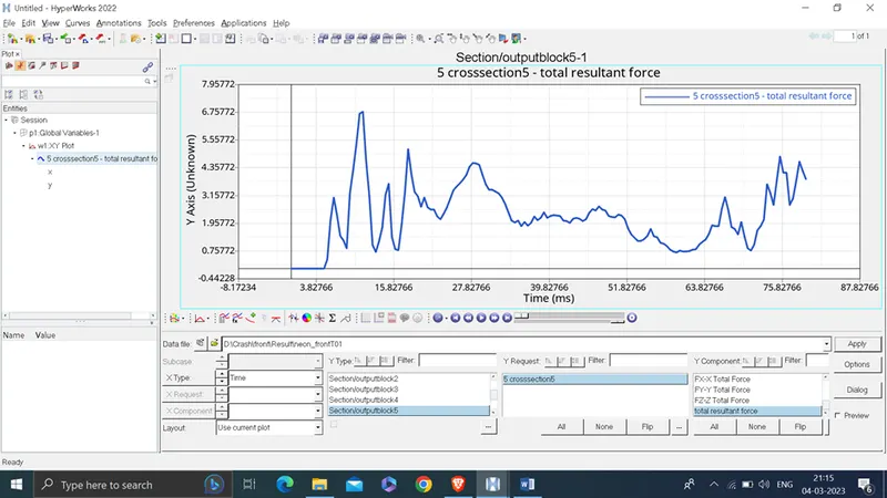
Axial forces received on the rails from bumper Left is 6.77 KN
- Axial force received Bumper (Right )
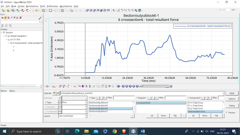
Axial forces received on the rails Right from bumper is 5.13 KN
- Sectional force received at the rail cross section (left)
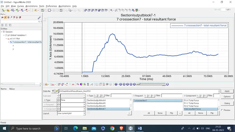
The sectional force experienced at the left rail 16.10 kN.
- Sectional force received at rail cross section ( right )
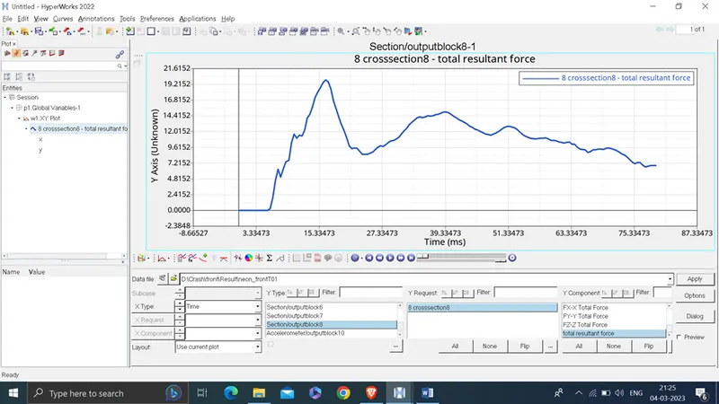
The sectional force experienced at the Right rail 19.90 KN
- Acceleration curve received at the base of B pillar (left)
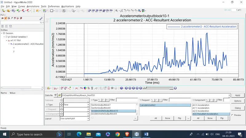
on the left base of B pillar the maximum resultant acceleration experienced is 1.818 mm/ms^2.
- Acceleration curve received at the base of B pillar (Right )
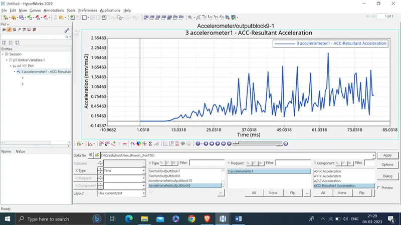
on the right base of B pillar the maximum resultant acceleration experienced is 2.10 mm/ms^2
total intrusion at node 66695;
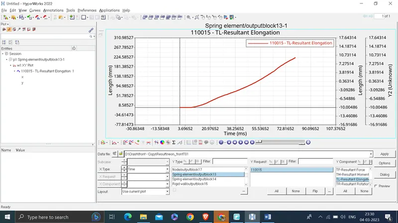
Total intrusion is 222.43 mm
total intrusion at node 66244
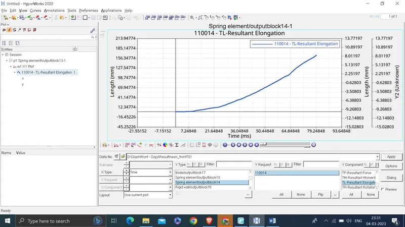
Total intrusion is 165.51 mm
Rigid wall force
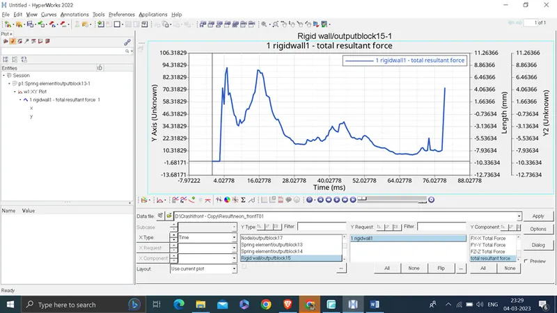
Conclusion : The given model was simulated for the frontal crash using Radios
The graphical results were plotted for all the test cases. From the simulation, it can be observed that there was minimum deformation in the cabin, and also minimum intrusion was found in the driver's seat area.