Assignment 6-Frontal Crash Simulation Challenge
Frontal crash-BIW
objectives
To set up the given simulation conditions on the BIW model for frontal crash simulation in HyperMesh/RADIOSS and discuss the results .
Check unit system and either follow[Mg mm s] or [Kg mm ms].
Create appropriate interface ,friction 0.2 and recommended parameters.
Make sure of no penetrations and intersection.
Correct rigid bodies if any issues.
Create rigid wall with friction 0.1.
Compare the model weight with the full scale 300k nodes model and use added masses to reach target weight 700kg while getting CG about the required range.
Initial velocity 35 mph.
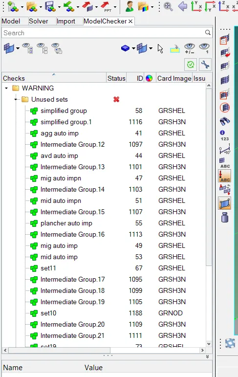
Use model checker to ensure good quality.
Time-step :0.5 to 0.1 microseconds.
Run 80 ms
procedure to import the solver deck
click on import option >select import solver deck>import the neon_0000.rad file
import solver deck
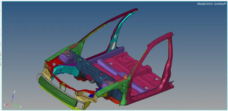
the model has been imported succesfully as shown above
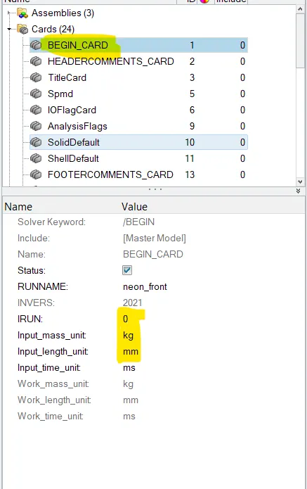
Check unit system and either follow [Mg mm s] or [Kg mm ms].
click on begin card and check the units in kg mm ms as shown in below image
2.Create appropriate interface ,friction 0.2 and recommended parameters
right click in model browser and select create option >select contact >name it as self contact
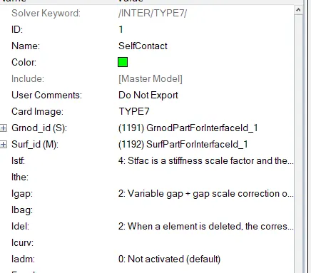
now click on the above created self contact a tab will open below the tab area , set the parameters stmin=1.0, istf=4 igap=2 ,idel=2 Fric=0.2(given) gap min=0.55 , inacti=6
click on grnod id(slave) and select all the components (72) as slave
click on surf id for master nodes and select all the components (72) as master

2.CREATE RIGID WALL
procedure to create rigid wall
select the model browser and right click on the tab area >select create option >select rigid wall>click on rigid wall a window will open just below the tab area .
from the engineering data click on arrow and select a node on the front bumper and hit proceed .change the xm value to 4700 so that a gap will be mantained between rigid wall and front bumper
from the normal specify the x coordinate -1 so that it normal will be opposit the direction of the motion

from the support just specify the below snap values
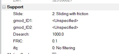
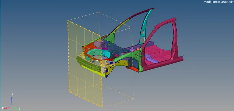
now the rigid wall has been created as shown in above snap
penetration check
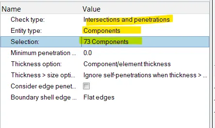
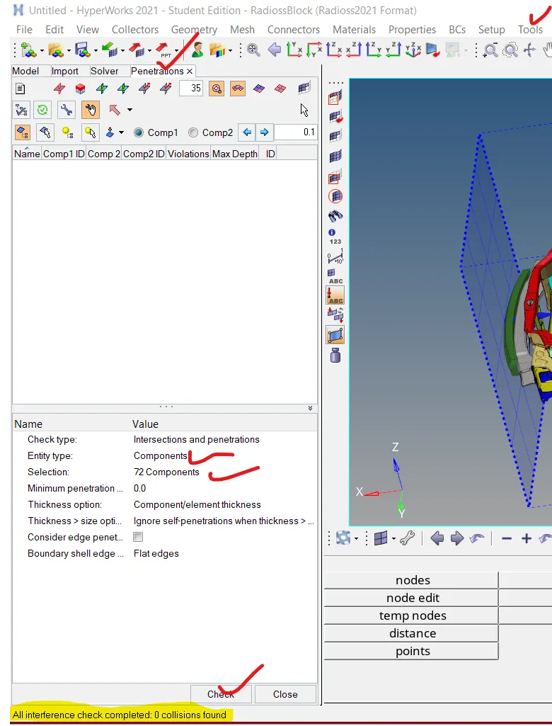
click on tools from the main menu >select penetration check , a window will open just below the tab area where we have to click on the selection and select all the components and in entity id select components. in check type make sure intersection and penetration is selected.
Now hit on check
INTIAL VELOCITY/INVEL
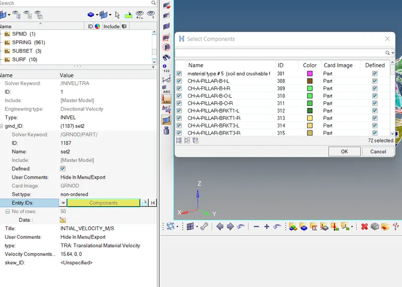
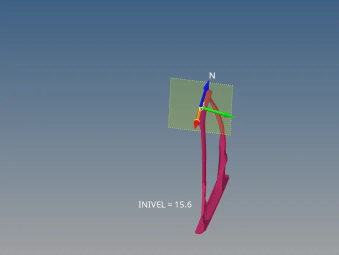
The velocity input for this simulation as per the Standards is 35mph so when we convert it to m/s by just multiplying it with 0.4470 and the input velocity will be converted to (m/s) 15.6464m/s.
To create a velocity
Go to solver browser >> Create >> boundary conditions (BC) >> Inivel
Define the Node group on which specified initial velocities are applied (grnd_ID1). For our simulation, we will be selecting all components
set the velocity component in x cordinate to 15.6
FRAME AND SECTION
We will be Creating Sections at A-Pillar, Shot Gun, rails, and the Bumper in order to Study the sectional forces. We have to know how the forces are transmitted from the Bumper to the Dashboard and the rate of deformation. It is done in order to ensure the safety of the passenger.
Certain components have to deform more than the other so that the forces are distributed correctly leaving very little force left to transmit inside the cabin.
FRAME
procedure to create frame .right click from the solver browser >click on create>select frame a window will open from the pannel >select the origin node ,select the x/z cordinate >select the the plane yz or yx as shown below
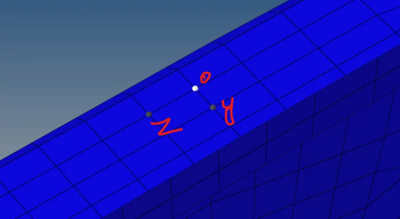
now the frame has been created
SECTION
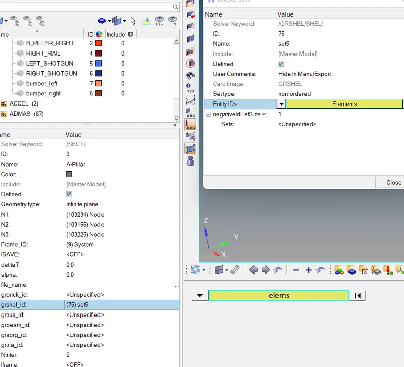
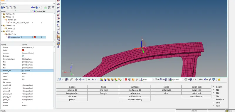
right click in the solver browser >select SECT>click on the section in the solver browser >select the 3 nodes N1 N2 N3 >select the frame ID and click on systems to select the frame >set the alpha =0.1 and dellta=0.6
Define the cutting plane by a group of elements and its orientation by a group of nodes (grshell_ID)
the section has been created as shown in below image
similarlly we can use the same procedure to create section and frame for the remaining components
SPRING ELEMENTS
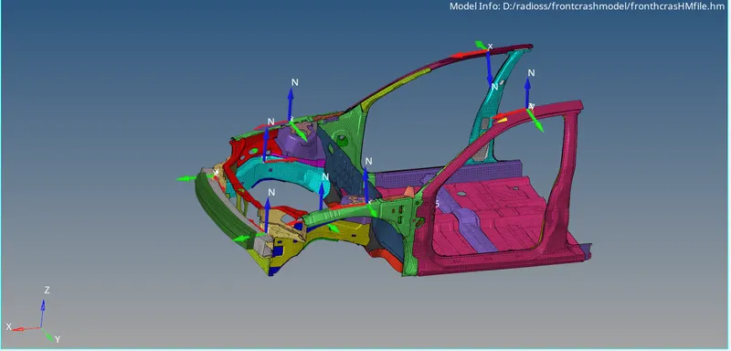
Intrusions on the dash wall 66695,66244.
we have to find the intrusions at node provided with respect to car body. So to find the results at the specified parts, create spring between the node provided and the base cross member of car,
first of all we are going to find out the nodes by their node id
click on temp node >select node by id >enter the node id >click on add
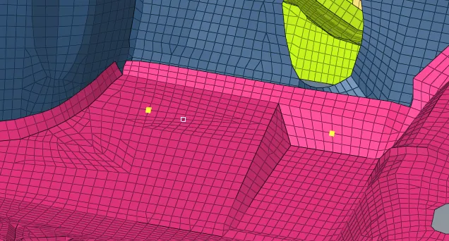
Now to create spring element we have to click on the 1D from the pannel >click on spring select the node that we have find out by node id select the 2nd node at cross beam
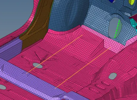
Go to model Browser >> Create >> Property >> Rename as Springs
After creating a property, a new tab will open there we have to select CARD image as P4 SPRING and Mass as 0.01, and Stiffness as 0.001 and assign all these properties to the spring.
Make sure to create a Time History file for these Springs Individually so that we can view the intrusions.
ADDING MASS TO SYSTEM
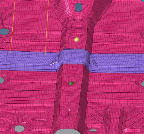
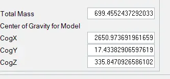
The mass of the given model was about 188 Kg, which is very less for a car model. This mass only made sense if we consider the model which is BIW. However, for running a simulation for the crash, we must consider a car model thus we must add mass to this model. We can add mass where other components will sit like the seat and passenger. The aim is to reach 700kg while maintaining a proper Centre of Gravity location and also to change the center of mass for the system it will help us to not lift from the rear wheel side while impact
Go to Solver browser > Right-click > ADMAS
Select type 1 which will distribute the given mass over the selected area
Select the nodes and keep on adding mass till the CoG reaches the desired position
CREATE ACCELERATION NODES:
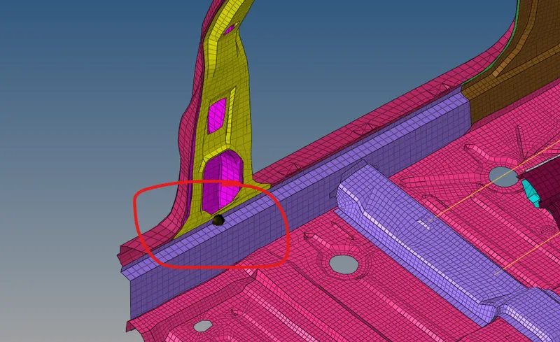
Creating Accelerometer at both sides of the B pillar.
An accelerometer is a basic technology that converts mechanical motion into an electrical signal. It is an electromechanical device that measures acceleration forces, whether caused by gravity or motion.
To create accelerometer
Go to Model browser >Create > Accelerometer > Select Node_ID > Select node >Proceed
This is done to get the Acceleration output of the Crash i.e., rate of deformation.
Output requests:
- Sectional force in the rails at location of indicated node 174247.
- Axial force received on the rails from bumper.
- Shotgun cross sectional forces.
- A pillar cross section.
- Acceleration curve received on the accelerometer at base of B pillar (on B pillar rocker).
- Intrusions on the dash wall 66695,66244.
output request/create TH part
Go to the solver browser > Right click> TH
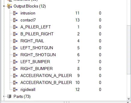
Under TH, we have a lot of options. We have requested INTER output for the Type-7 interface, SECTIO option for all the sections, ACCEL option for accelerometer, and SPRING option for intrusions.
Once we create all these TH cards, we have to select the respective elements for them.
For example, select spring elements for SPRING, accelerometer for ACCEL, and so on.
I have kept the variable as 1 and DEF in every card
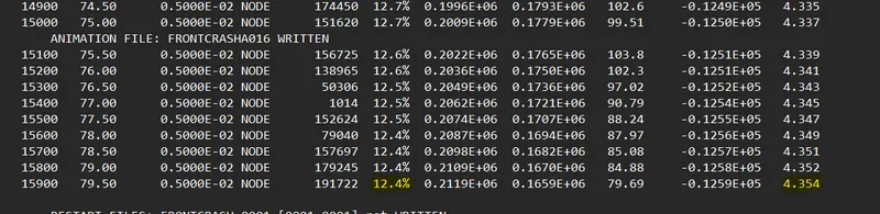
case 1
energy and mass error check
case 1
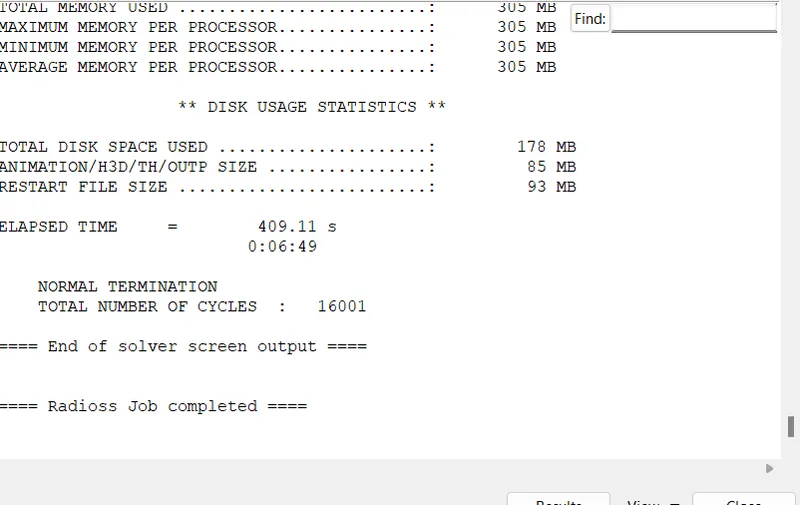
time step =0.005
model checker for the good accuracy only warning is showing we can ignore them
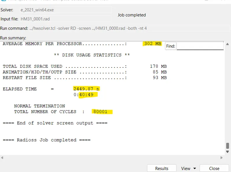
case 2
node time step=0.001
energy and mass error check
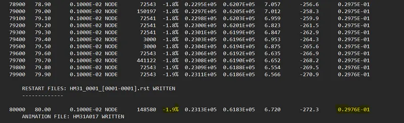
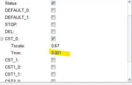
in the case 1 we got huge mass error and also the energy error are very high nearly about 12% we did a mistake by specifying the time step of 0.005 in case 1 the simulation takes 10 minutes to complete the job .Such high error values could mean that there was mass addition in the simulation to prevent time-step from being too small.In the case 2 we decrease the time step to 0.001 and there was negligible amount of mass addtion and also the energy dissipation was very low indicated by the negative sign in energy error.the case 2 simulation time was 40 min due to the lower time step
RESULT
we can analyse the results from hyper graph and hyper view
click on the client selector and select the hyper graph 2D or hyper view
we have to input the file T01 for hyper graph and H3D for hyper view
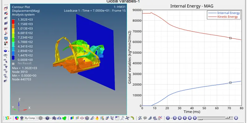
displacement KE ,Internal energy
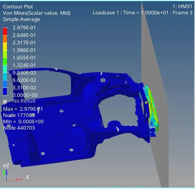
vonmises stress
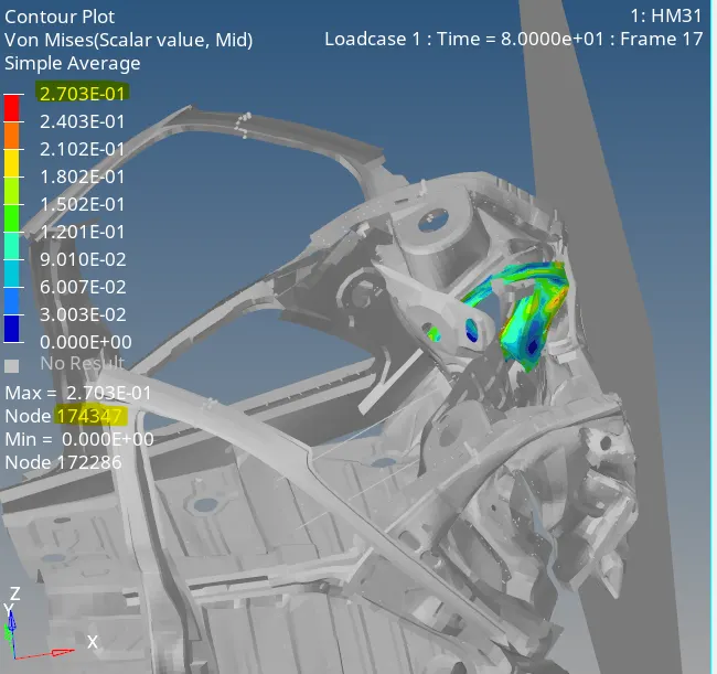
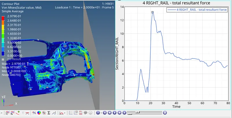
Sectional force in the rails at location of indicated node 174247
right rail cross sectional force
The maximum cross-sectional force at right Rail is 13 kN. The force acting on the rail is the force transmitted by the bumper during the crash. The force transmitted by the bumper to the rail is not equal as some of the force will be absorbed by the Bumper resulting in deformation.
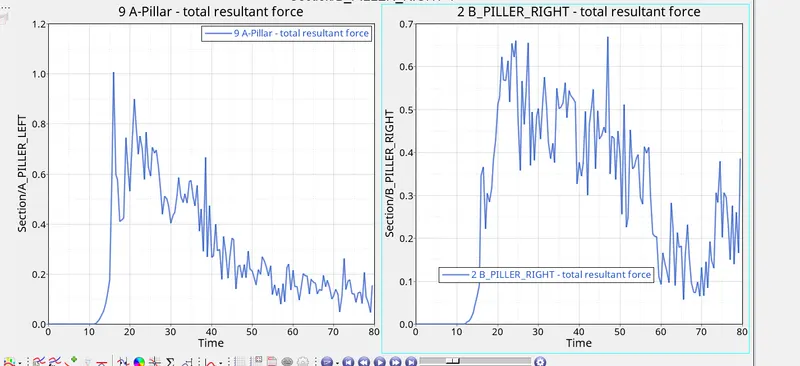
The maximum cross-sectional force at Left A-Pillar is 1kN whereas the maximum cross-sectional force at b-Pillar is 0.65kN . when the car hits the rigid wall, there will be some amount of force coming into the A-pillar at both sides. These forces coming to the A-pillar are nothing but the force transmitted from the rail and the shotgun. The force flowing into the LH and RH of the A-pillars will not be equal and hence the deformation of the elements will differ accordingly
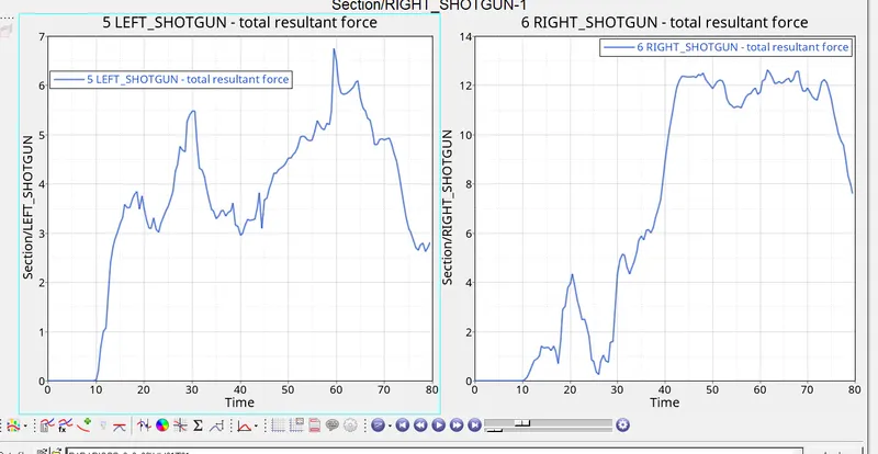
The maximum cross-sectional force at Left Shotgun is 6.9 kN whereas the maximum cross-sectional force at Right Shotgun is 12.5kN. The Force that occurred at the shotgun is the force transmitted from the rail section. The force propagation is not the same at both the rails and hence the amount of deformation at both the shotgun sections are different. Once the Compressive force reaches its maximum value it starts to deform rapidly.
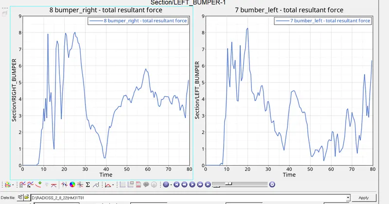
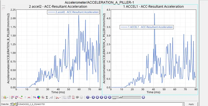
Maximum acceleration at accel2 = 2.1 mm/ms2 at t=60 ms
Maximum acceleration at RH = 4.25 mm/ms2 at t=40ms