Assignment 6-Frontal Crash Simulation Challenge
Frontal Crash Simulation
Objective:
To set up the given frontal model of the car and crash it against a rigid wall to obtain the desired result .
- Sectional force in the rails at location of indicated node 174247.
- Axial force received on the rails from bumper.
- Shotgun cross sectional forces.
- A pillar cross section.
- Acceleration curve received on the accelerometer at base of B pillar (on B pillar rocker).
- Intrusions on the dash wall 66695,66244
Case setup and execution:
- First we import the given model using the radioss solver deck.
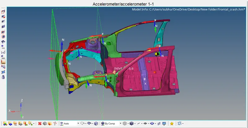
- Now we create a rigid wall for the crash. We can create this using right click in the model browser. After creating we select the node where we want to create the rigid wall and then enter the appropriate properties of the wall.
- Create a type 7 contact.
- Now we check for the COG and total mass of the model by going under the tools tab. We now do mass balancing by adding masses to make sure that the total mass is about 700. Now we check the COG again to make sure its at the right place.( Center of the model , near driver seat).
- Now we create intrusion at nodes 66695 and 66244 by using the temp nodes.
- For creating the section forces, we have to create a frame first, and then create the section. For this we go to the solver browser and right click to select the 'frame>mov' and then select the node1>node2>node3 appropriatly. Once this is created we again use right click to select 'sect' and then select the referance frame id. Now we enter the node1,node2,node3 id's here again, and select the elements for grshell id.
- Repeat step 5 for both A pillars, shotguns, rails and the bumper.
- Now we add two accelerometers at the base of B pillar. This can be done by using right click in the model browser.
- To get all our required outputs, we need to create an outputblock. This can be done in the model broswer using the right click. We create as many output blocks as required for us.(Rigid wall,accelerometer,intrusions,section forces,contact forces.)
- Create a boundary condition of Inivel and give the value of 15.6.
- Now go to the engine cards and make sure the engine run time is 80ms and change the engine_dt_noda to 0.0005ms.
- Finally we can check for any errors by going to the tools tab and selecting the model checker>radiossblock.
- If we get no errors we are good to run the simulation.Go to the analysis tab and hit radioss by selecting include connectors and giving number of threads as 4( -nt 4).
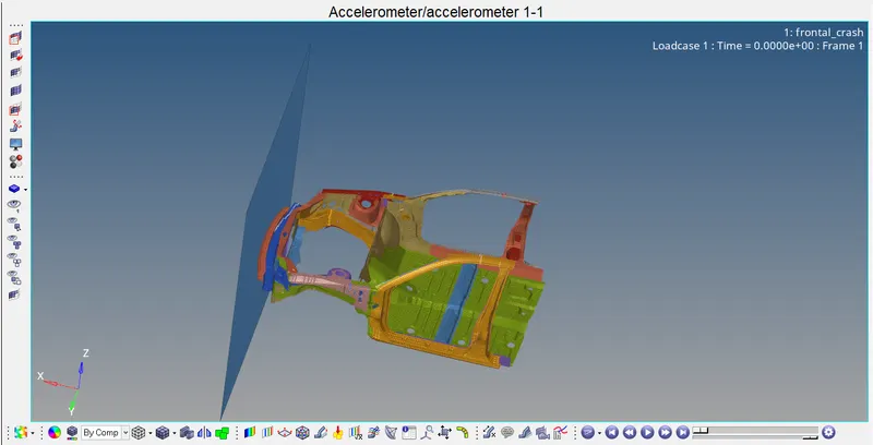
- After the simulation is done we can open the H3d file in hyperview and the T01 file in hypergraph2d and view our results.
Images and Graphs of the simulation:
Model setp:
H3d file:
Results:
- Energy plots
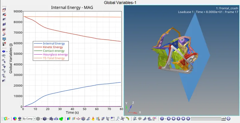
- The total energy is a contant throughout the entire simulation at 85000.
- Kinetic energy goes down from 85000 to around 62000.
- Internal energy increases from 0 to 23000.
- The hourglass and energy remains 0.
2. Contact Forces
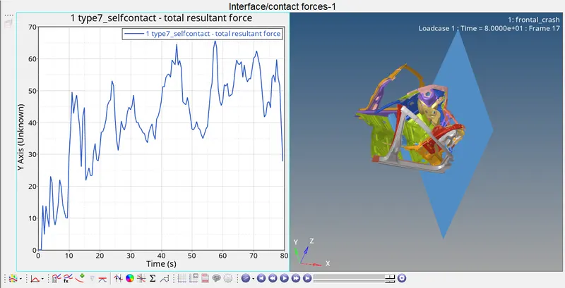
- This is the plot of a type 7 contact
- The highest value observed here is 65N.
3. Accelerometers
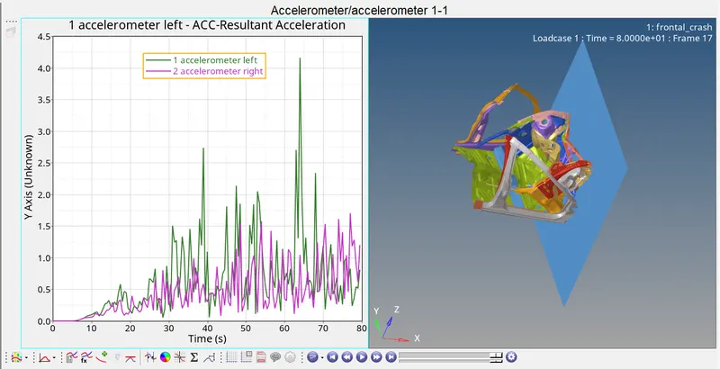
- The graph is completly irregular with lots of ups and downs.
- The highest value observed here is about the 1st accelerometer at around 4.2m/s^2.
4. A-pillars
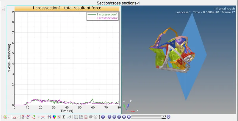
- The plots for the A pillars are totaly irruregular which implies the deformation is compltetly non uniform. Also we can observe that the deformation of the A pillar on the left is not the same as the deformation on the right due to the difference in the curves.
5. Shotguns
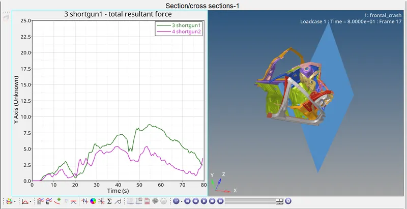
- The deformation of the shotgun on the left is comparatively higher than the deformation on the right. Once again we can understand that the impact of the crash on the vehicle is non uniformly distrubted, hence causing more damage to the left part of the vehicle more than the right.
6. Rails ( Rails 1 force is obtained at the node 174247).
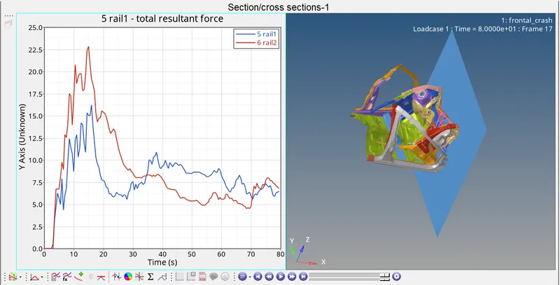
- The rail at the node 174247 undergoes lesser deformation than the deformation on the other side. The highest deformation occurs at the 2nd rail at about 23N.
7. Bumper
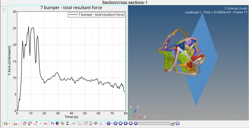
- The bumper is the first component that will be impacted when the crash takes place and is expected to observe the most of the energy and make sure that lesser amount of force is transmitted to the other components. Therefore we can observe that there is a huge increase in the graph at the start of the simulation and it goes down towards end.
8. Rigid wall
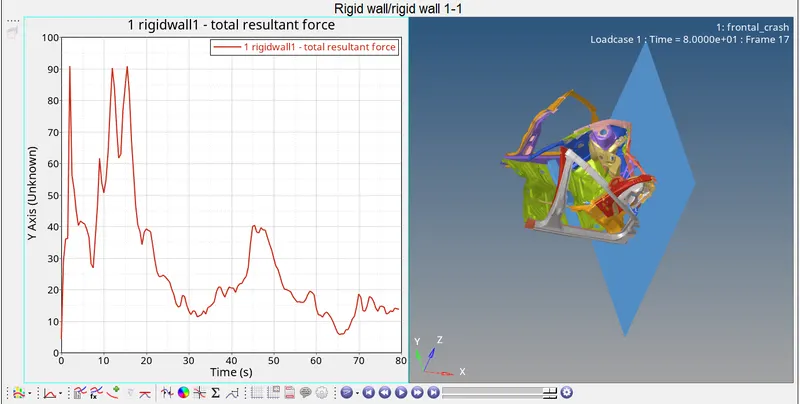
- The rigid wall force increases to the highest level at the initial time of the crash to a value of about 90N and then gradually comes down towards the end of the simulation.
9. Intrusions
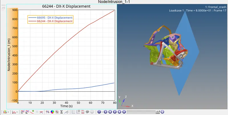
The Intrusion value for the node 66244 is about 90.
Intrusion calculation:
For NODE 66244:
The initial distance of the node from the referance point = 794.310(obtained using Node distance)
Displacement after the crash = 80.
Intrusion = 794.310-80 = 714.314.
CONCLUSION:
The given model has been succesfully simulated to obtain the desired results:
- Energy plots.
- Total energy-85000
- Kinetic energy-62000
- Internal energy 23000
2. Contact forces
- Type 7 contact
- Highest value 65
3. Accelerometers
- Highest value 1st accelerometer(left)-4.2m/s^2
4. Intrusion
- Referenace-794.310
- After simulation-80
- Final intrusion-714.314
5. Cross sectional Forces
- The plots have been obtained , and the curves for most of them are irregular.
- From this we understand that this is a non uniform deformation. The force gets transmitted to the inner body in a non uniform manner.
- The bumper observes most of the energy at the front which significantly reduces the damage caused in the inner part of the vehicle.
The entire simulation files are attatched in the form of an ZIP file below.