Assignment 6-Frontal Crash Simulation Challenge
#Project 1 - Frontal Crash Simulation Challenge
Aim:
To perform the crash on the frontal section of the car with wall and analysis where stresses are working on it.
Objectives:
Frontal crash - BIW
- Checking the unit system and either following [Mg mm s] or [Kg mm ms].
- Creating appropriate interface, friction 0.2 and recommended parameters.
- There should be no penetrations and intersections.
- Creating a rigid wall with friction 0.1.
- Adding masses to reach target weight 700kg while getting CG about the required range.
- Adding Initial velocity 35 mph.
- Running a model checker to ensure good quality.
- Time-step: 0.5 to 0.1 microseconds.
- Running 80 ms.
Procedure:
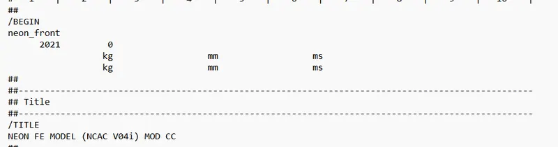
1) Check the unit system:
Open the given starter file to check the unit system.
2) Check the intersections and penetrations:
Go to Tools>Penetrations Check> Select the components
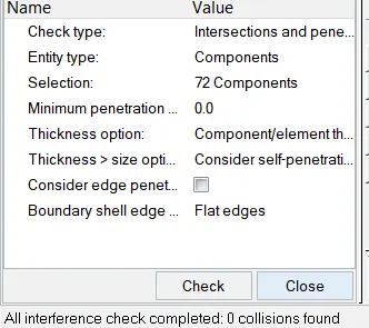
( There were no penetrations and intersections found in the model)
3) Interface creation:
Create a type 7 interface for all the components of the model. Go to Solver>Create>Inter>Type7. Set the recommended parameters.
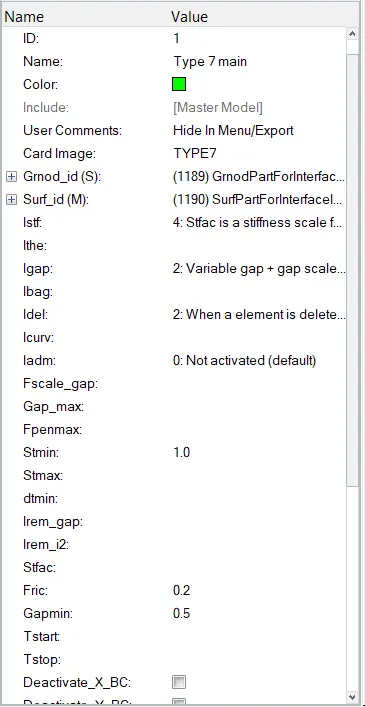
Select all the components in the master surface and slave nodes.
4) Rigid wall creation:
Create the outermost node on the bumper of the car using the temp node option
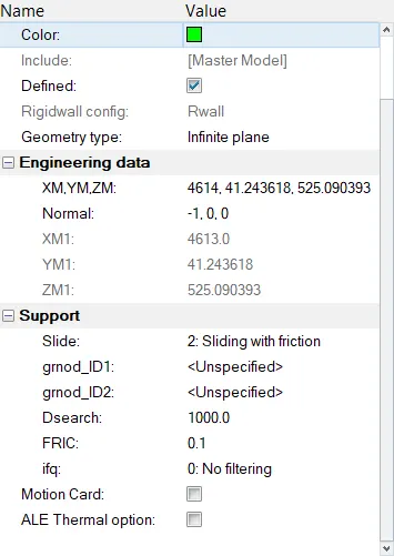
Right-click on the solver browser and go to Create>Rwall>Plane.
For the location of the rigid wall select the created temp node and provide a 10 mm translation on the x-axis so that wall cannot touch the model. Define the normal in the negative x direction.
5) Mass Balancing:
Go to Tools>Mass Details> Mass ,Cog and Inertia
Initially mass of the model is 188 Kg, in order to represent scaled model into full car model, the mass should be converted to 700 Kg.
Right click on the Solver deck and create ADmas card to add mass to the model.
An additional mass of 512 g is added to each node so that the full car model is represented.
(Here COG is located exactly near the driver's seat)
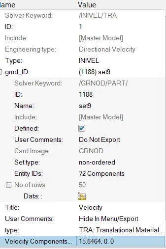
6) Initial Velocity:
To create initial velocity right click on the solver browser and then navigate to Create>BOUNDARY CONDITION>INIVEL.
Under INIVEL card select all the components as the entity for grnd_ID.
Specify the velocity of 15.6464 mm/ms in the x-direction.
7) Run Time and Time step:
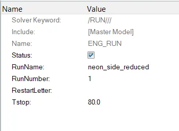
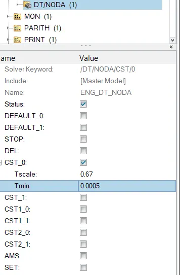
Go to Cards under Model browser, To check the run time open the ENG RUN card and set the Tstop as 80 ms. For the time step, open the ENG_DT_NODA card and change the Tmin value to 0.5 microseconds or 0.0005 ms.
OUTPUT REQUESTS:
SECTIONAL FORCES:
1. On RAILS:
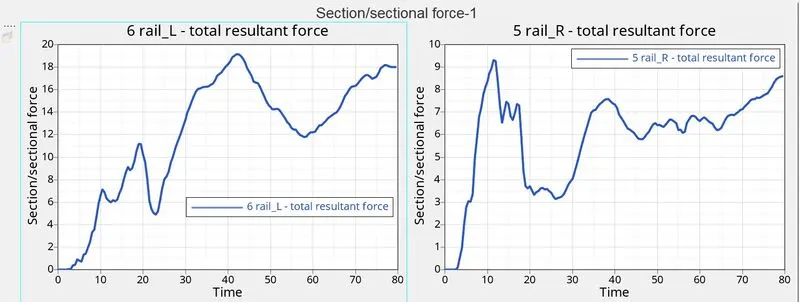
Sectional forces on rails VS Time
The maximum cross-sectional force at Left Rail is 19.1 kN/mm at t= 42ms whereas the maximum cross-sectional force at the Right rail is 9.31kN/mm at t=11.5ms. The force acting on the rail is the force transmitted by the bumper during the crash. The force transmitted by the bumper to the rail can be unequal due to which the force received at the LH rail may differ from the RH rail. During a crash, the rail will get into direct contact with the rigid wall which will increase the compressive force and then deform. Therefore, the compressive force drops down.
2. On Shotguns:
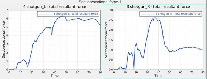
Sectional forces on shotgun VS Time
The maximum cross-sectional force at Left Shotgun is 6.33 kN/mm at t=46.5ms whereas the maximum cross-sectional force at Right Shotgun is 2.62 kN/mm at t=37.5ms. The Force that occurred at the shotgun is the force transmitted from the rail section. The force propagation is not the same at both the rails and hence the amount of deformation at both the shotgun sections are different. Once the Compressive force reaches its maximum value it starts to deform rapidly. Therefore, the Compressive force is decreasing as referred from the graph. As the crash happen continuously, the shotgun will come into contact with the Rigid wall as found in Animation, the rigid wall also exerts the force directly on to the shotguns and hence there is an increase in the Sectional force as seen in the graph.
3. On A-Pillars:
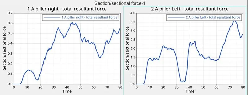
Sectional forces on A-pillar VS Time
The maximum cross-sectional force at Left A-Pillar is 3.66 kN/mm at t= 73.5 ms whereas the maximum cross-sectional force at Right A-Pillar is 0.608 kN/mm at t=44ms when the car hits the rigid wall, there will be some amount of force coming into the A-pillar at both sides. These forces coming to the A-pillar are nothing but the force transmitted from the rail and the shotgun. The force flowing into the LH and RH of the A-pillars will not be equal and hence the deformation of the elements will differ accordingly. During a frontal crash, the sectional force reaching the A-pillars are coming in from the rails and shotgun, hence the force at the A-pillars will be less when compared to the front sections. When the compressive force between the wall and car is maximum, the rail and shotgun get in contact with the rigid wall which causes the shotgun and rail to exert more force. This force then propagates to the A-pillars and hence the force reaching the A-pillar increases again.
Intrusion Spring:
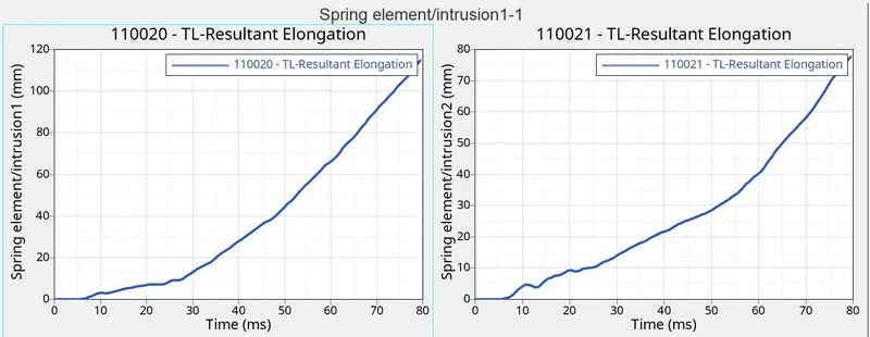
Intrusion spring VS Time
To check the Intrusion at the dash wall at the particularly given node, we have created the spring over the place. The intrusion at this particular node is calculated in order to check whether the crash will hamper the safety of the driver due to the deformation that occurred at the front portion of the vehicle. From the above graph, we can see that the maximum intrusion occurred in the spring (Node 66695,121754) during a crash is 77.629 mm and the maximum intrusion occurred in the spring (Node 66244,121868) during a crash is 114.82 mm. Practically this elongation referred to which extent the foot pedal or the passenger's legs will move once the crash is happening. From the animation, we can notice that there is not much deformation that occurred at this location and the elongation is also less. Hence, we can conclude that there are fewer injuries will happen to the Passenger/driver.
Acceleromter:
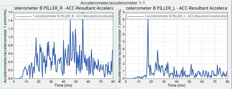
Accelerometer VS Time
As we all know that an Acceleration is the rate of change of velocity. To measure the acceleration, we have placed the accelerometer near the Rocker of B-Pillar on both sides. From the above graph, we can see that initially, the acceleration is constant before the vehicle hitting the rigid wall. Once the Car hits the rigid wall with the initial velocity, The acceleration of the vehicle during the crash is not constant across the structure. The front of the vehicle slows down immediately as it hits the rigid wall, while the rest of the structure decelerates at a slower rate as seen in the graph. As seen from the graph there is a sudden increase in the acceleration, this might be because of some vibration that occurs during the crash with respect to the point where the accelerometer is placed.
Maximum acceleration at LH = 8.40 mm/ms2 at t=17.5 ms
Maximum acceleration at RH = 1.59 mm/ms2 at t=55.5 ms
Axial forces on rail of bumper:
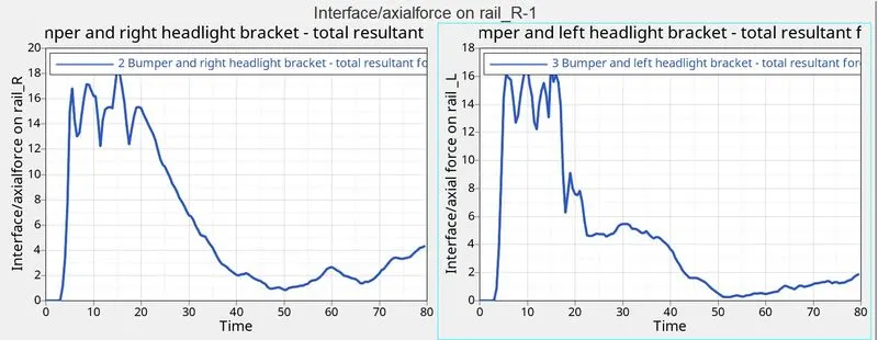
The force from bumper to rail VS Time
From the graph we can see that initially there is no axial force is transmitted from the bumper to the Rail. Once the Vehicle hits the rigid wall, first the Bumper will start deforming and transmitting the strain energy to the rail sections. From the graph, we found that the Maximum axial force received from the bumper to the Left hand rail is 16.89 kN at 15 ms and the Maximum axial force received from the bumper to the Right hand rail is 18.31 kN at 15 ms.
RESULTS:
- Frontal crash analysis was carried out on the given front half of a BIW model of the Dodge Neon as per the given requirements. The output requests were also generated after the creation of cross-sections in each of those regions. Acceleration and intrusion values were also measured at certain points of the model.
- The analysis also proves the importance of the crumple zone - which is the front portion of the BIW in this case. It absorbs most of the forces generated during a frontal crash and therefore, protects the occupant(s).