Assignment 6-Frontal Crash Simulation Challenge
Live session batch
Aim: To create deck setup for the frontal crash simulation of BIW of car and simulation to be carried out and discuss the results.
Procedure:
The Units system used in the simulation is found out by using the starter file.
The penetration is not there as it checked.
The type 7 Contact is created with the recommended option.
The contact between the bumper and the headlight is created using type 7 contact.
The rigid wall is created.
The initial velocity of 15.64 mm/ms^2 was applied to the nodes on the BIW in X-direction.
The intrusions are created.
The accelorometer is created.
The TH cards for the cross section is created.
The simulation is run using the radioss option.
Results and discussion:
Energy and mass error is seen in the output file to check whether the results are acceptable.
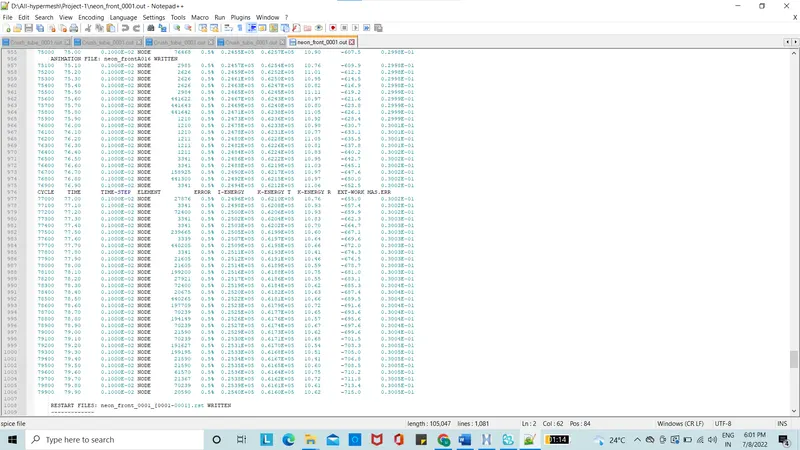
Figure 1: Output file
The energy error is 0.5% which is acceptable less than 1% and the mass error is 0.03 which acceptable.
Plot of internal energy and kinetic energy is taken into account to find out how the energy absorption takes place in the system. The internal energy is nothing but the distortion energy. The kinetic energy decreases as the system energy increase thereby increase in internal energy.
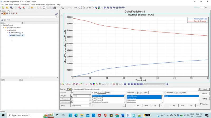
Figure 2: Internal and Kinetic energy
The Hourglass energy is negligible when compared to total energy. The kinetic energy when drops is absorbed into internal energy so that the total energy remain constant. Contact energy is the energy generated to avoid penetration.
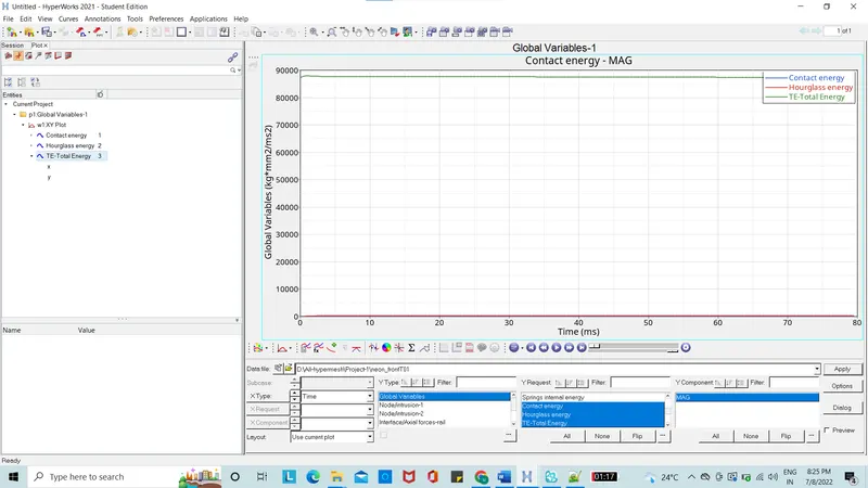
Figure 3: Hourglass, contact and Total Energies
Sectional Forces on the rails, shot gun and pillar A is taken into consideration to see what are the forces generated.
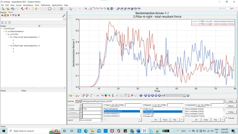
Figure 4: Pillar A-Cross sectional Forces
The Pillar A-cross sectional forces on the right pillar-A is 0.58KN at 21ms whereas the left pillar-A is 0.49KN at 15.5ms.
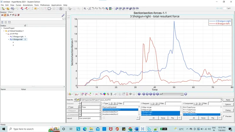
Figure 5: Shotgun Cross sectional forces
The Shotgun cross sectional force at right side will be is 17.5KN at 50ms whereas on the left side will be 13KN at 37ms.
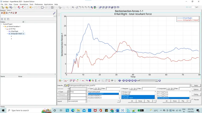
Figure 6: Rail Cross sectional forces
The rail cross sectional force on the right side is 26KN at 13ms and the on the left side which is also at the node of 174247 is 17KN at 35ms.
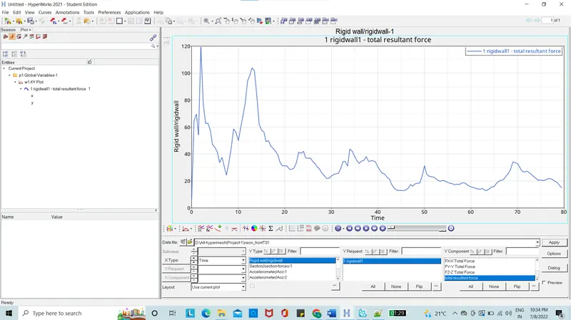
Figure 7: Rigid wall force
The rigid wall force is generated with 120KN at 1.2ms.
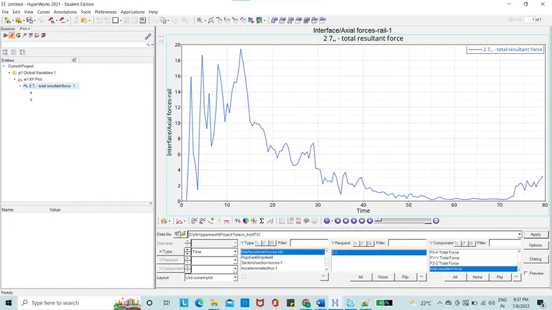
Figure 8: Axial forces on rail of bumper
The axial forces on the rail of bumper is 19KN at 13ms.
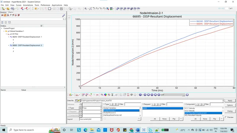
Figure 9: Resultant displacement of intrusion
The Intrusion at the particular position is checked so that the passenger and the driver are safe and how the legs of the passenger and the driver is move when the crash happens.
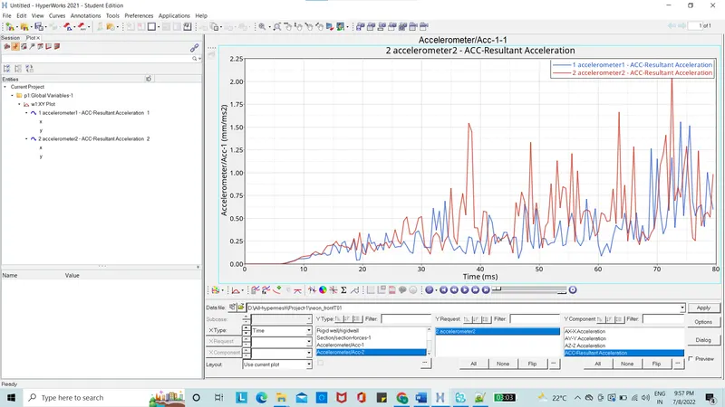
Figure 10: Accelerometer
The rate of change of velocity is accelerometer. To measure acceleration, accelerometer is placed near the rocker of B-pillar. The maximum acceleration at left side is 1.6 mm/ms^2 at 74ms and on the right side it is 2.1 mm/ms^2.
Learning outcomes
How to set up a frontal crash test in radioss
How to create cross section.
How the components deform and absorb energy
How the safety of passenger and driver is managed
How to check the energy error and mass error is to be balanced so that simulation obtained is correct
Debugging the errors in the simulation
Conclusion:
The simulation is carried out for the frontal crash for the given BIW in radioss solver the results obtained and validated. The results and graphs are plotted. It’s observed that the energy is absorbed the is significant deformation and the minimum possible damage to the passenger and driver.