Assignment 6-Frontal Crash Simulation Challenge
OBJECTIVE: To perform frontal crash simulation with the given car model and also plot the result from the output request.
PROCEDURE:
1. To import the given model to the radioss GUI.
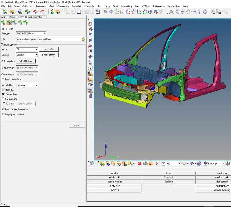
- Import> selecting file type as radioss>0000.rad>import.
- The file is imported.
2. To Check unit system.
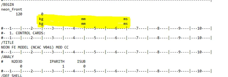
- We can check the unit system from the starter file or from the begin card.
3. To Create appropriate interface ,friction 0.2 and recommended parameters.
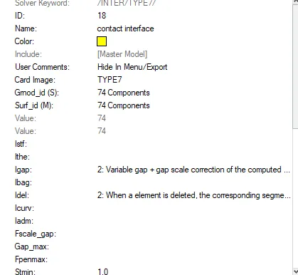
|
Ishell =24 |
QEPH 4 nodes shells are best combination of cost and accuracy. | |
|
Ismstr=2 |
Full geometric nonlinearities (default)with possible small strain formulation activation in RADIOSS Engine. | |
|
Ish3n=2 |
Standard 3 noded shell (C0)with modification for large rotation(default) |
|
| N=5 | Number of integration points set to 5 for accuracy bending. | |
|
Ithick=1 |
Thickness change is taken into account for accuracy. |
|
|
Iplas=1 |
Iterative plasticity for good accuracy. | |
|
Fric=0.2 |
Frictional forces. |
- Right click on the model tree> Create>contact, and provide suitable as above and delete the rest of the interface.
3. To check if there is any penetrations and intersection.
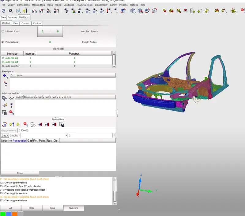
- The penentration is checked in hypercrash software
- To open Hypercrash >hypermesh>application on the tool bar> hypercrash.
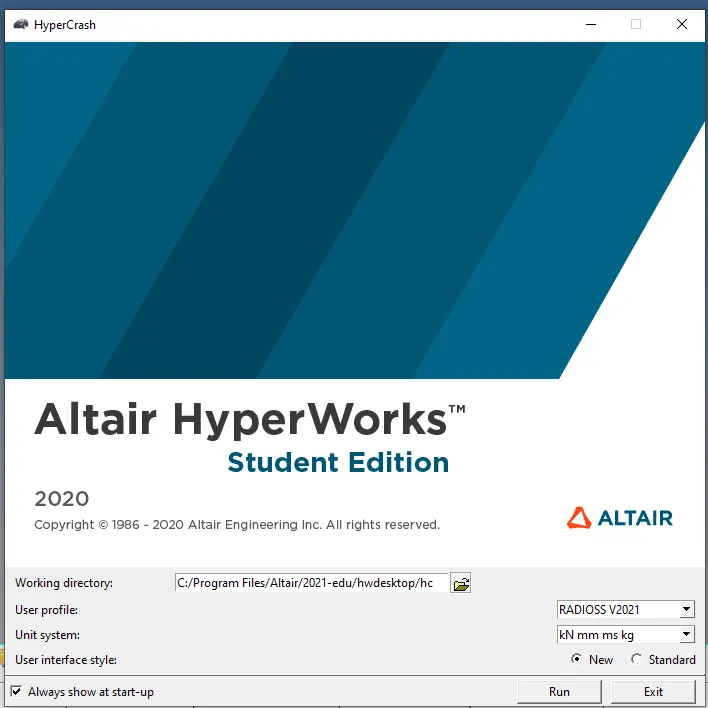
- Choosing the SI unit > To import the model> drag the file 0000.rad file to the GUI, the model will be imported.
- To check for pentration in Hypercrash .
- Quailty from hypercrash tool menu> Check all solver contact interface.
- There is no penetration found.
4. Correct rigid bodies if any issues.
- Removed all the unwanted rigid bodies form the model.
5. Create rigid wall with friction 0.1.
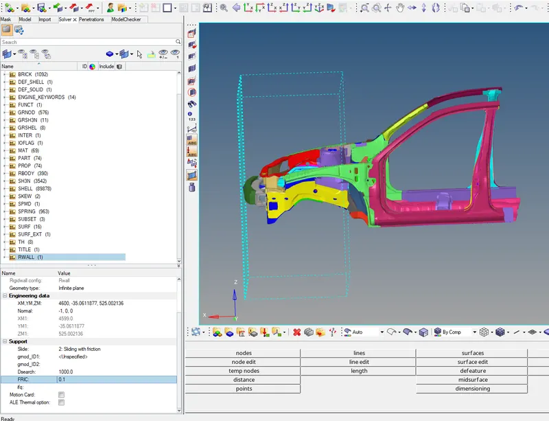
- In Hypermesh Right click on the model tree > Create > Rwall
- Geometry type- infinte plane> XM, YM,ZM- Selecting the middle of the bumper.
- Selecting the -1 as the normal.
- Slide> 2. sliding with friction.
- Dsearch 1000.
- Fric is 0.1
- The rigid wall is created.
6. To add masses to reach target weight 700kg while getting CG about the required range.
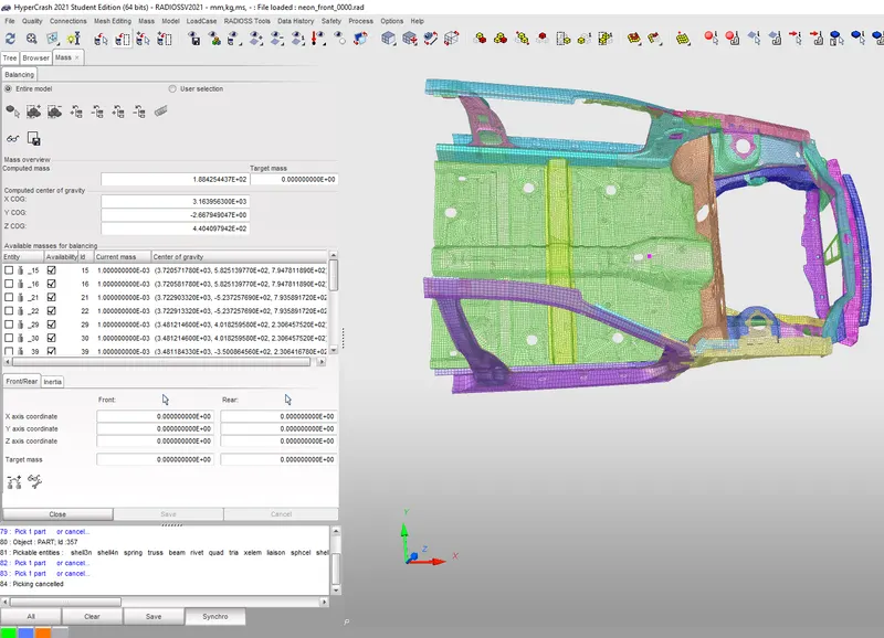
- Tool menu> Mass> Mass balancing , total mass is 188 kg of the half scale model and the COG point is around the centre console.
- Comparing with full scale model the mass should be 700 kg and cog point should be below at the end and in between passanger and co passanger seat.
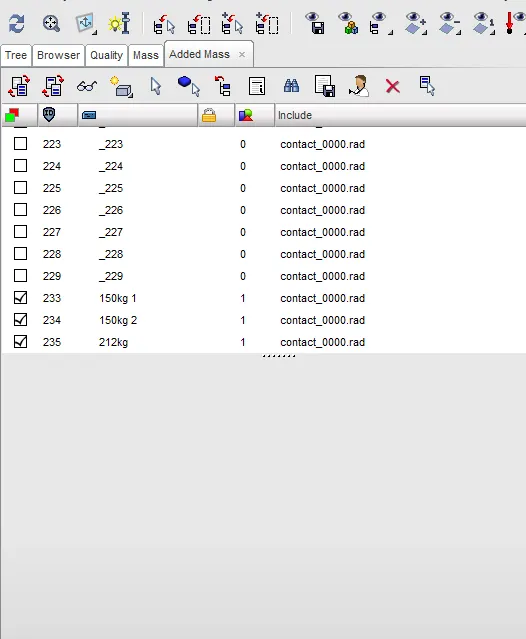
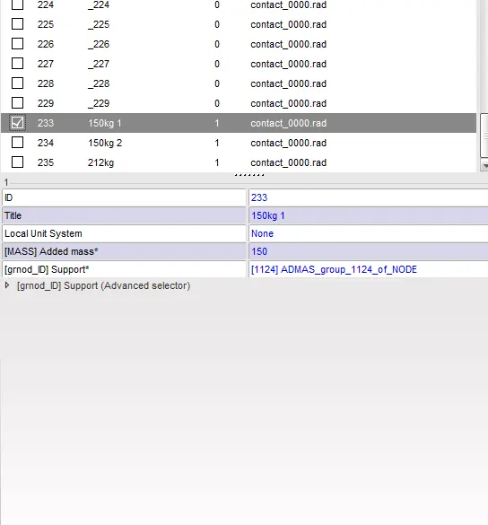
- In Hypercrash to add mass, Load case> added mass.
- Create new > Type1> mass> right clicking on support> selecting the nodes in graphics. to add the mass.
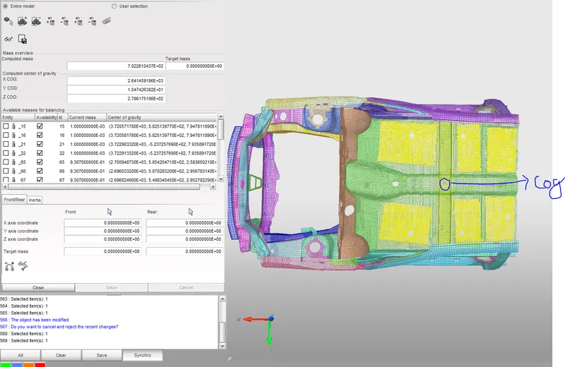
- Masses are added in such a way that total mass shoud 700 kg and COG as per determined.
- The mass added are 150 kgs are added at the 1st set of row , 150 and 212 are added in reset of the row
- Total 180+150+150+220=700 kg.
- The COG point is now shifted to the desired location.
5. Initial velocity 35 mph.
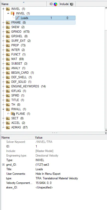
- To create the initial velocity card
- Right Click on the solver tree> create> Boundary condition> Inivel
- To convert 35MPH to MMPS
- 1MPH= 0.45MPS
- 35MPG =? 35x0.447=15.64
- Velocity component= 15.64.0.0 , in X direction.
6. Time-step :0.5 to 0.1 microseconds.
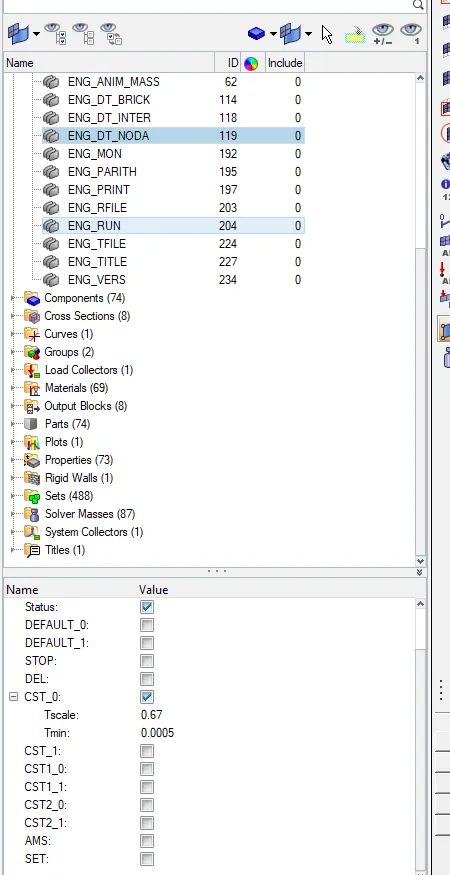
- Model tree>cards > ENG_Dota_Noda
- Given 0.5 Micro sec
- Converting 0.5 micro sec to 0.0005 milisec .
7. To Run the simulation for 80 ms.
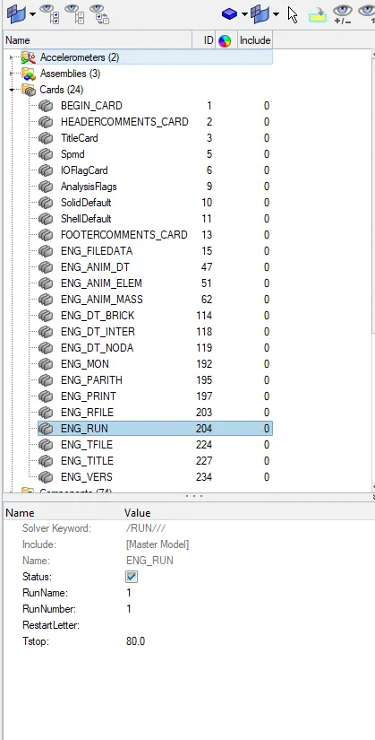
- Model tree>cards > ENG_Run.
- Tstop=80.0
8. Using model checker to ensure good quality.
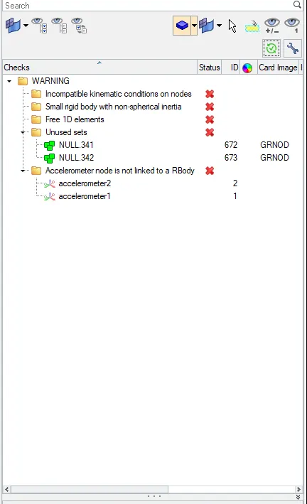
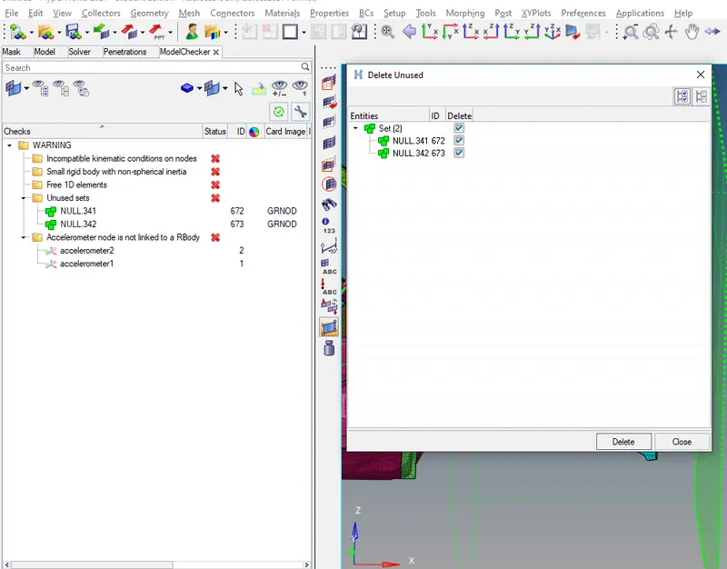
- Tools> Model checker> Radioss block>Run checker.
- There no error only warning.
- The warning can be ignored.
- The Unused set is removed by deleting from tools > unused.
9. Creating frame and section in respective position for output section
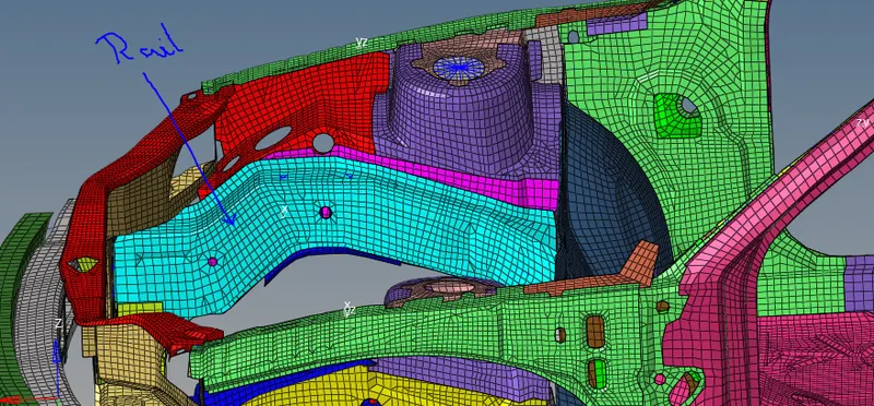
- By using Temp node to locate the position to create the section.
- Creating frame by right clicking on the solver browser >create> frame > mov selecting the node.
- Creating the Section on the rail, right click> create> Sect.
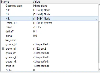
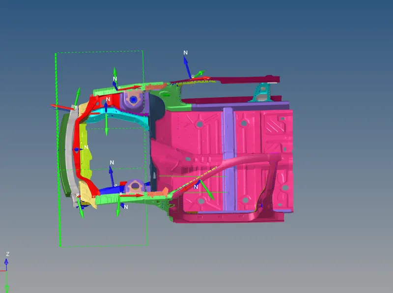
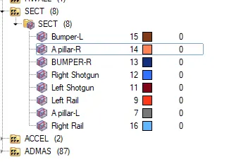
- Selecting the N1 , N2 and N3 respectively as per the frame.
- Right clicking on the grshel id > create and selecting the element.
- Frame and section is created for all the output request.
- Same procedure is followed for all the Output request.
10. To run the analysis.

- Hypermesh>analysis>Radioss>select the path to be saved.
- Include the connectors and -nt 4 to> Radioss.
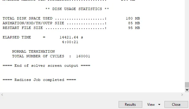
- Total Time taken to complete the Cycle is 4hrs.
11. To run the animation.
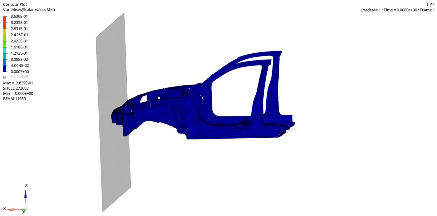
- Hyperview > Open >H3d File .
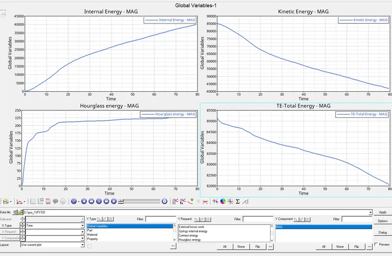
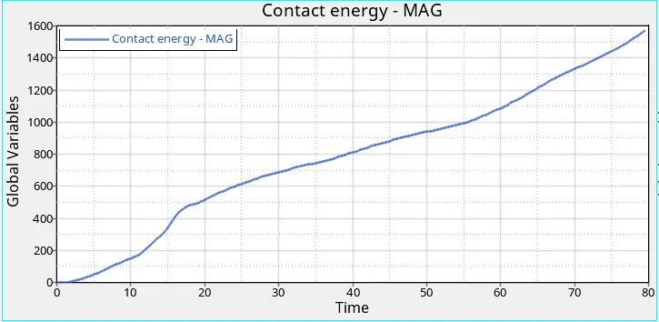
- The initial kinetic energy of the car is Maximum as soon as the model crashes into the the rigid wall the kinetic energy is reduced.
- As the kinetic energy reduces the internal energy increases.
Output Requests.
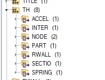
- TH cards are created inorder to plot the required output at that paritcular section.
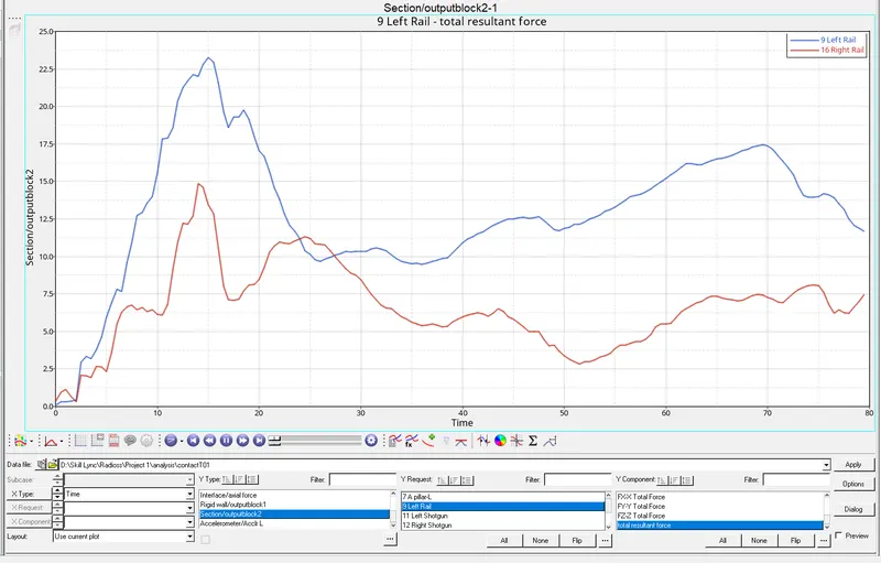
1. Sectional force in the rails at location of indicated node 174247.
- Using Hypergraph to plot the required output
- From the above graph we can see that the force on the left rail is more compared to right rail.
- At 14ms to 15ms the force has reached its peak in both the rails then the force is reduced.
2. Axial force received on the rails from bumper.
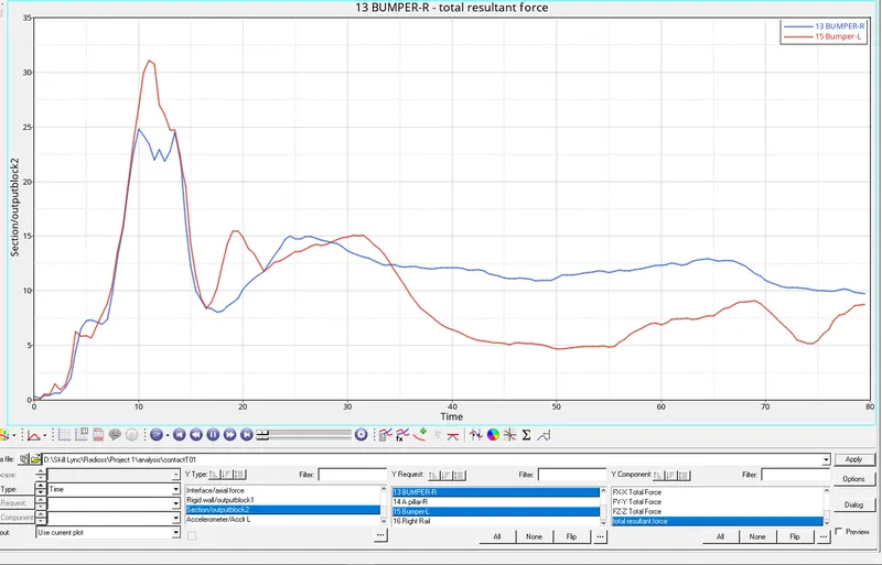
- The axial forces is initially 0 then increases as the car hits the rigid wall.
- The maximum axial force is 32kN/mm2 at 11ms.
- The force is transmitted from bumper to the rail and gradually decreases .
3. Shotgun cross sectional forces.
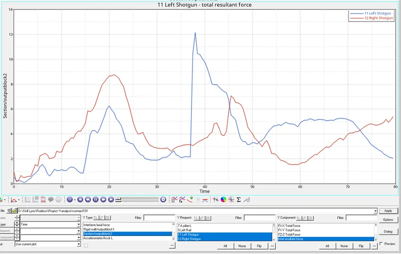
- The force on the left shotgun is more compared to the right shotgun.
- From the graph Maximum force on the left shotgun is 12KN/mm2 at 38ms and in the right it is 8.8KN/mm2 at 22ms.
- From the animation we can also see that left shotgun has undergone more deformation.
4. A pillar cross section.
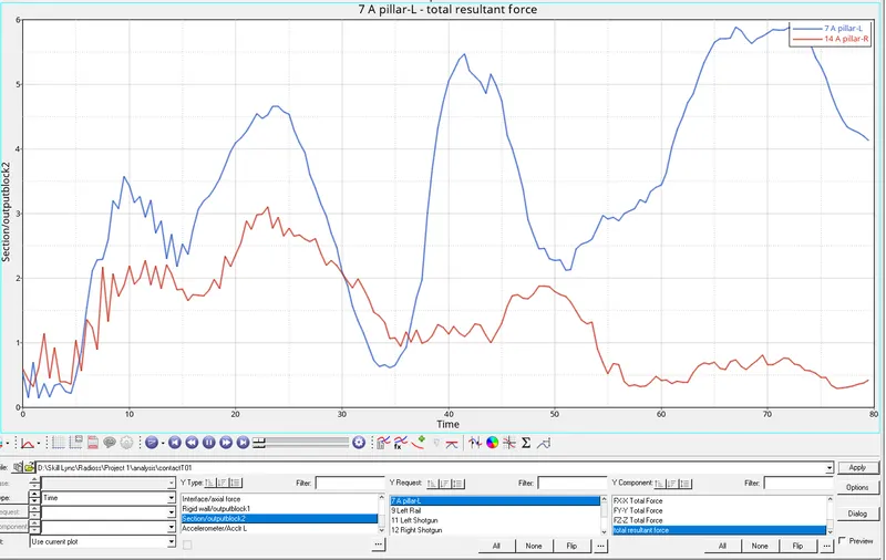
- The maximum force on the Left A pillar is 5.5KN/mm2 at 70ms.
- The maximum force on the right A pillar is 3.1KN/mm2 at 22ms.
- Here the deformation is higher in the left A pillar.
5.Acceleration curve received on the accelerometer at base of B pillar.
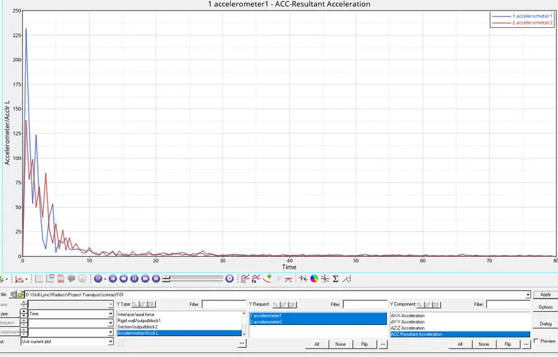
- From the above graph the Accelertaion has increased and decrease as the body hits the rigid wall and deaccelerates.
6. Intrusions on the dash wall 66695,66244.
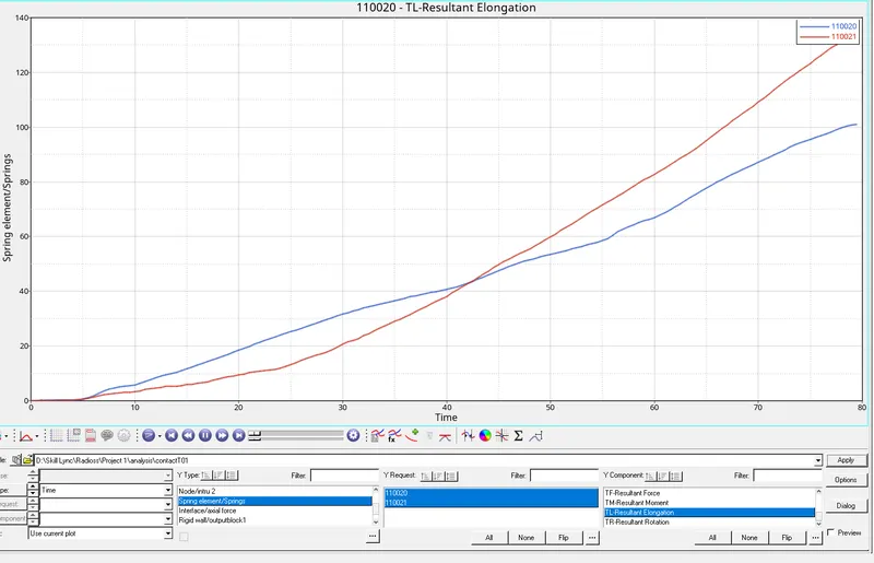
- Spring is created to check for the intrusion.
- The Maximum elongation is 101mm and 137mm respectively where the intrusion is very small as seen in the animation.
Conclusion:
- The force is reduced as the as it transmits from one component to another.
- Initially the maximum force experienced on the bumper is 32KN/mm2 > maximum force experienced on rails is 23kN/mm2 >maximum force experienced on shotgun is 13kN/mm2>maximum force experienced on Apillar is 5.5kN/mm2.
- So as the component deforms the force is absorbed and reduced as it travel from one component to another.
RESULT:
Performed the frontal crash simulation with the given car model and results are poltted as per the output request.