Assignment 6
Assignment 6
Question
Frontal crash-BIW
- Check unit system and either follow [Mg mm s] or [Kg mm ms].
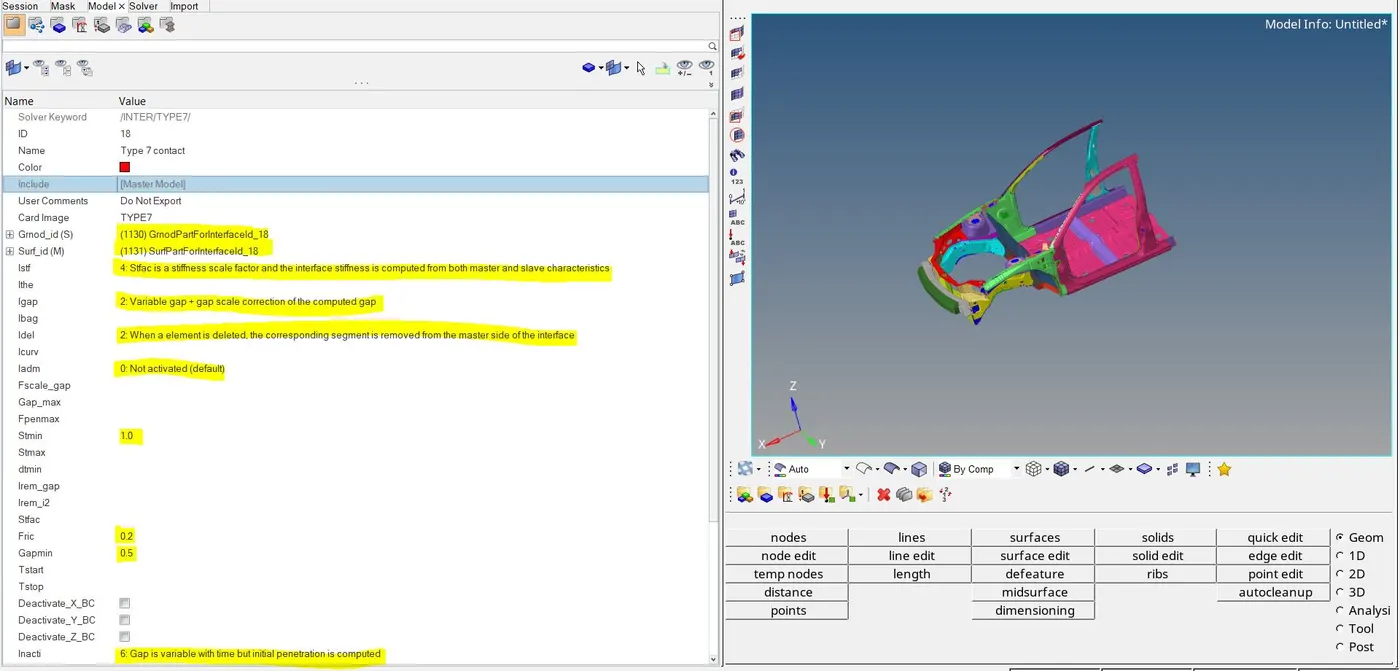
- Create appropriate interface, friction 0.2 and recommended parameters.
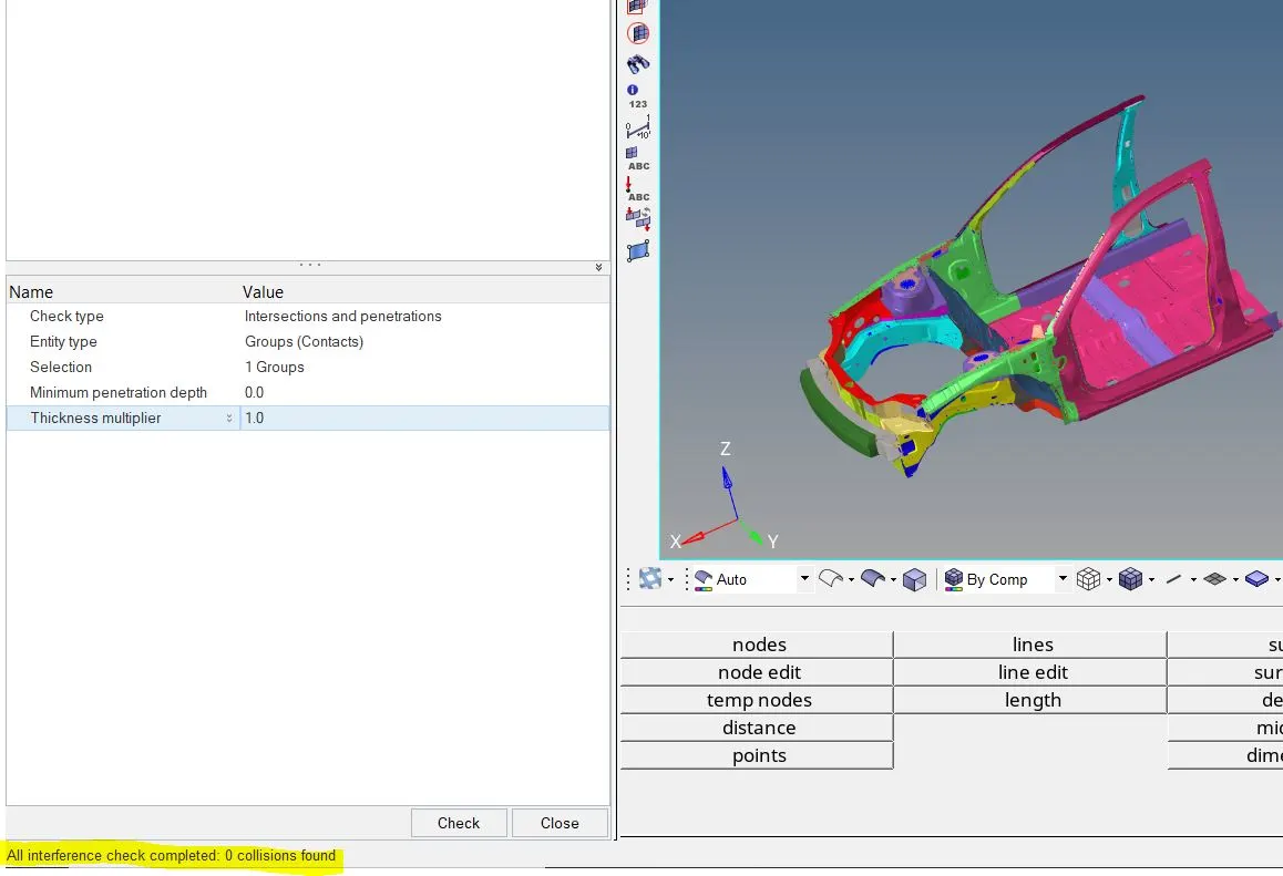
- Make sure of no penetrations and intersection.
- Correct rigid bodies if any issues.
- Create rigid wall with friction 0.1.
- Compare the model weight with the full scale 300k nodes model and use added masses to reach target weight 700kg while getting CG about the required range.
- Initial velocity 35 mph.
- Use model checker to ensure good quality.
- Time-step :0.5 to 0.1 microseconds.
- Run 80 ms.
Output requests:
- Sectional force in the rails at location of indicated node 174247.
- Axial force received on the rails from bumper.
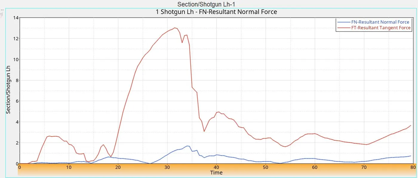
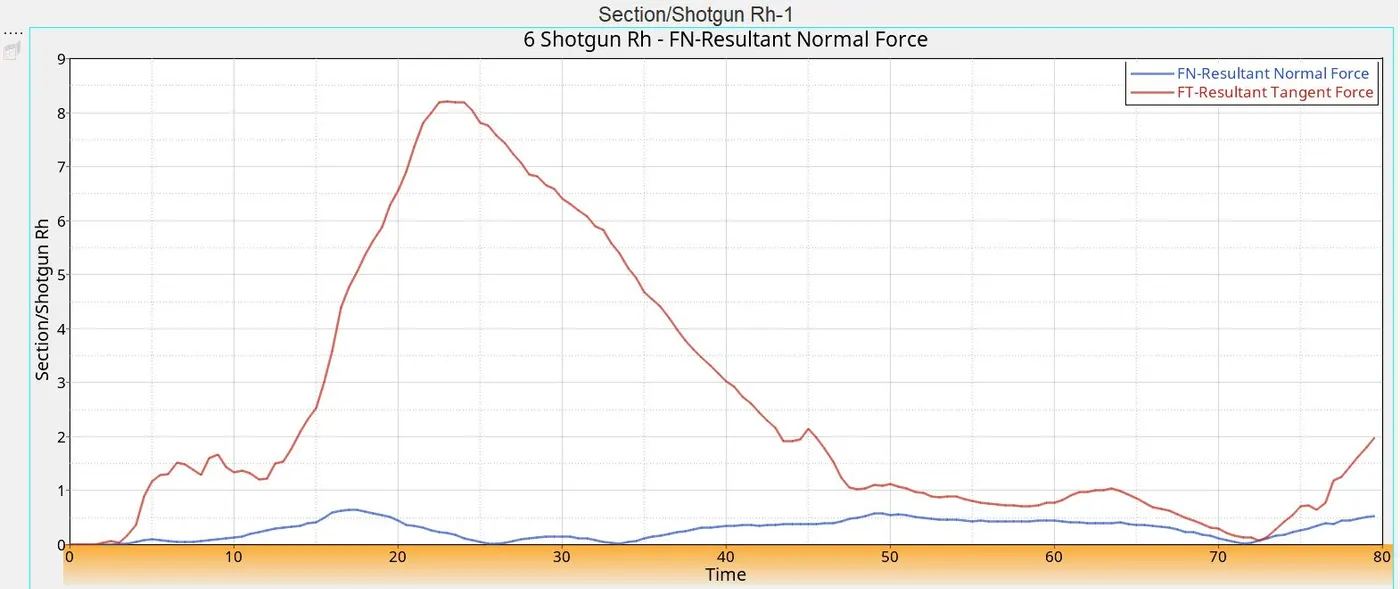
- Shotgun cross sectional forces.
- A pillar cross section.
- Acceleration curve received on the accelerometer at base of B pillar (on B pillar rocker).
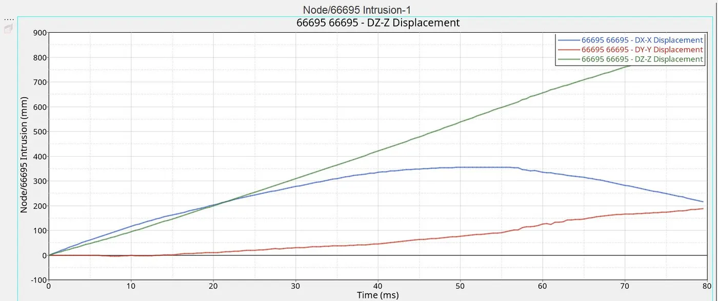
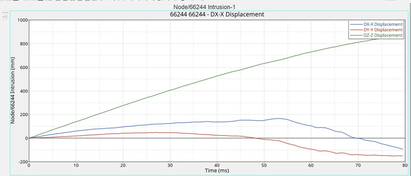
- Intrusions on the dash wall 66695,66244.
Note:
- Submit your simulation files including time and h3d files.
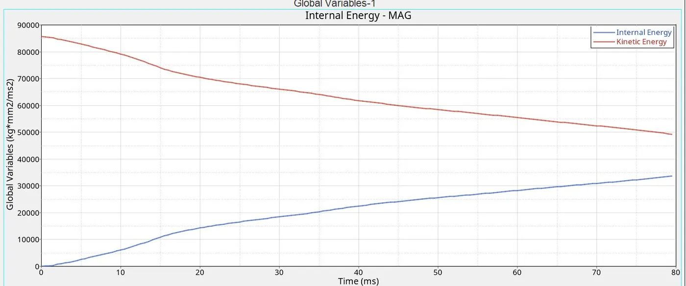
- Plot energies and notice any difference.
- Explain your errors and how to rectify?
Objective
To perform a frontal crash test for the given BIW (body in white) model and analyse the deformation and various types of forces produced during the crash. In this project, the velocity of car is set as 35 mph (standard car speeds for frontal crash as per FMVSS norms). The obtained outputs from the analysis are:
- Sectional forces in the rails at the location of indicated node 174247
- The axial force received on the rails from the bumper
- Shotgun cross sectional force
- A pillar cross section
- Acceleration curve received on the accelerometer at base of B pillar (on B pillar rocker)
- Intrusions on the dash wall 66695,66244
Introduction
The crash test is usually done in order to design the vehicle for crash energy management with the objective to reduce the occupant injuries. There are various types of crash test (frontal crash, roof crash, side crash) that are performed on a vehicle. In post processing, the data obtained from the crash testing is usually in terms of forces, stresses, displacements etc. that can analyse. The completion of the simulation is performed in hypermesh using radioss solver. The case setup is done in hypermesh and for post-processing, hyperview andhypergraph 2D is used. Different types of energies, Von-Misses stresses, plastic strains, acceleration curves and forces graphs are computed.
Initially the vehicle has been set to crash on a planar rigid wall. As the name suggests, the rigid wall is non-deformable and fixed. Different sections are created on parts of the vehicle body in order to analyse the forces. Along with this, accelerometer is created at the bottom of the B-pillar on the rocker, on the both sides. The mass balancing has been done on the body to get the COG just at the bottom of driver seat or on the rail.
Case setup:
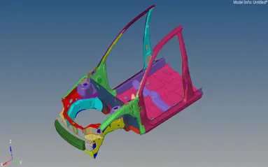
The given model is in. rad format. Due to the restriction of node in Hypermesh student edition, only partial model (up to B-pillar is taken for consideration).
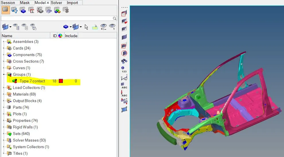
In hypermesh, under model -> groups, all the type 7 interface cards were present in the model were deleted and only one type 7 cards are created for all components. In the slave node and master node segments, all the nodes of the model were selected.
Penetration check
The given model is checked for any penetrations. It is the necessary way to remove the initial penetrations that is present in the model.
Tools -> Penetration check ->
Rigid wall creation
After completion of penetration check, the rigid wall is cretaed in front of the vehicle body. The rigid wall is basically non-deformable (non-yielding) retaining wall defined by user master node and a group of slave nodes.
View-> Browser-> hypermesh->solver
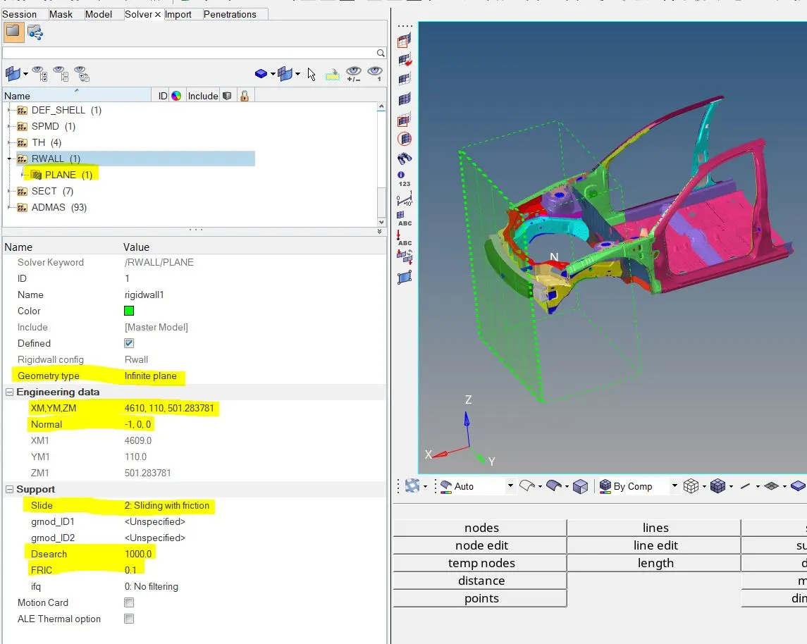
There are four types of rigid wall – out of four, the infinite plane rigid wall is created.The Dsearch( i.e., the search distance between for the slave nodes is kept as 1000mm). The type of rigid wall is set on Type 2: sliding with friction with a friction value of 0.1. A small virtual gap is kept in between the rigid wall and the bumper for illustration purposes.
Mass Balancing:
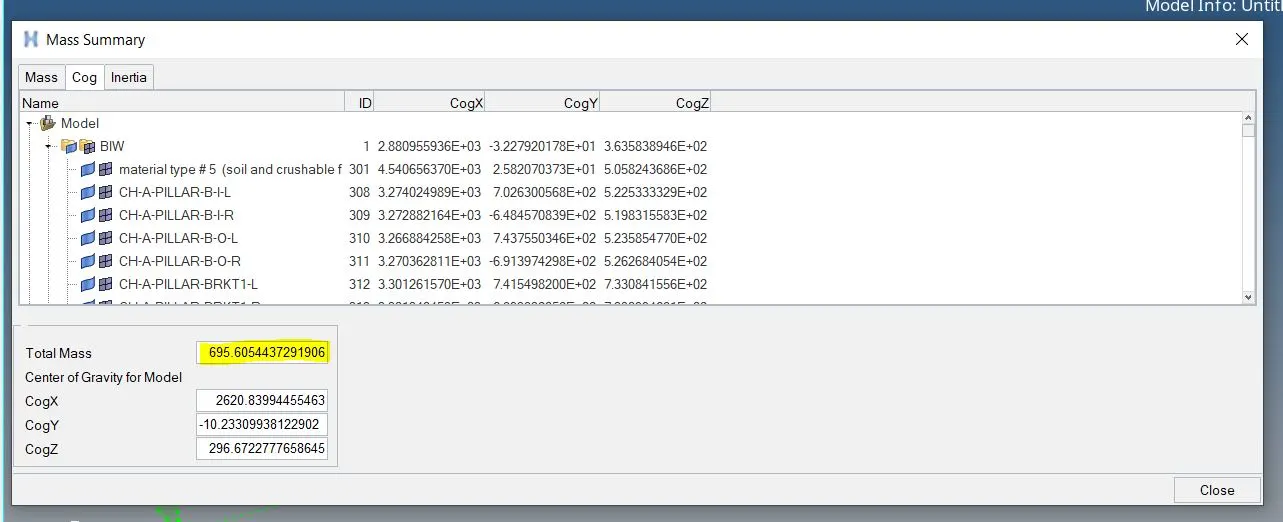
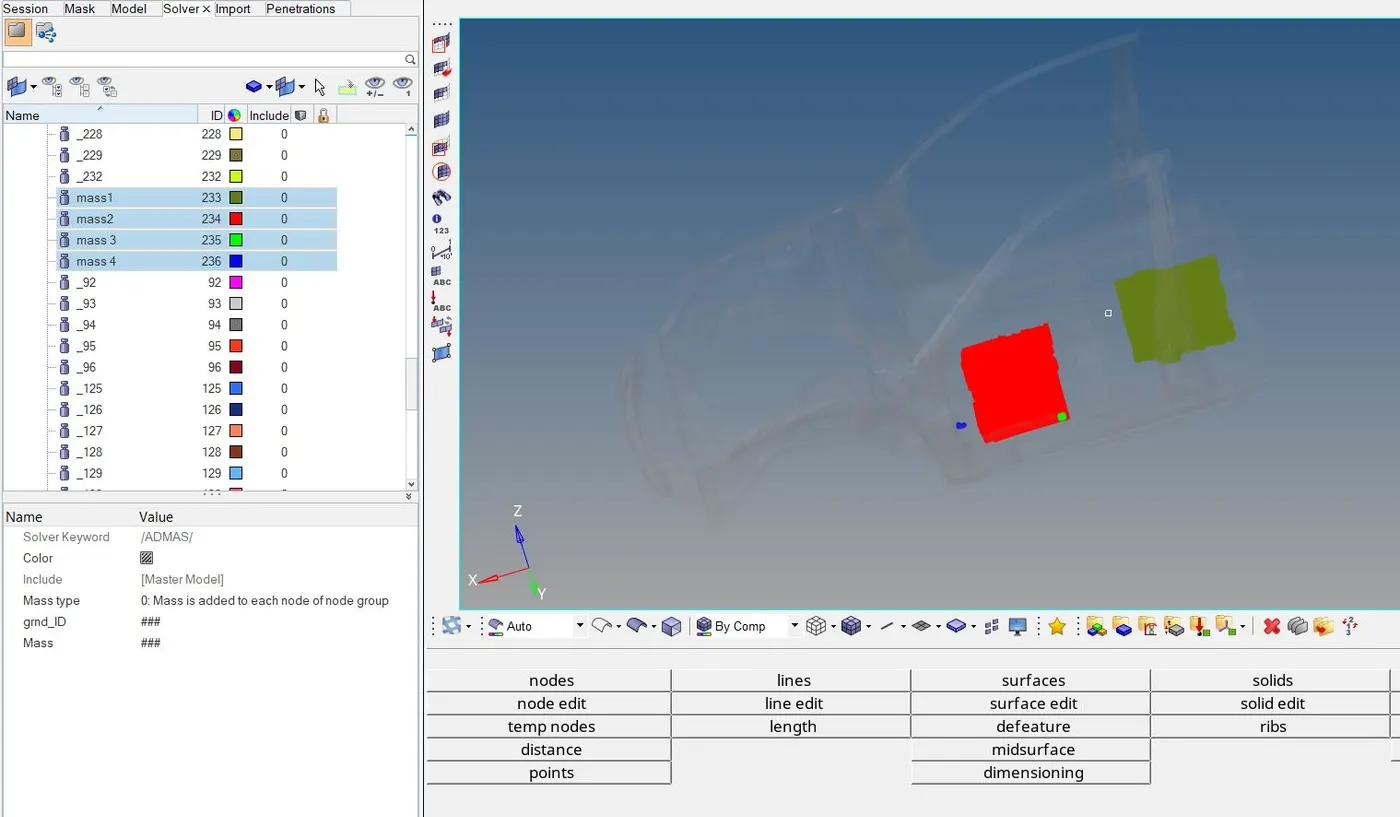
The initial mass of partial model provided with 188kg, while the target mass is around 700kg. The remaining mass is added manually on the body by trial and error. After trial and error, the COG came exactly on the rail, under the driver’s seat. The new mass after the addition became 695.6 kg.
Initial velocity
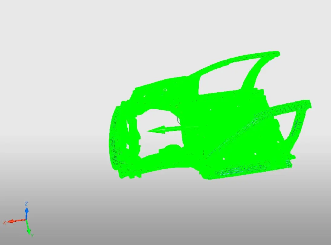
In this project, the velocity of car is set as 35 mph (standard car speeds for frontal crash as per FMVSS norms).
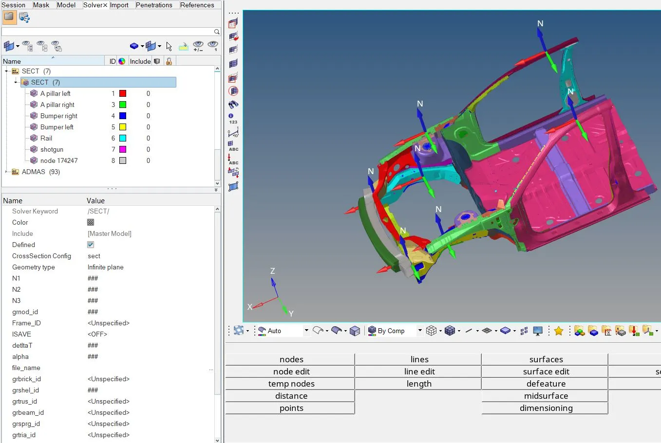
Sections
Sections are used to identify the value of the forces passing through the portion of the component.
The obtained outputs from the analysis are:
- Sectional forces in the rails at the location of indicated node 174247
- The axial force received on the rails from the bumper
- Shotgun cross sectional force
- A pillar cross section
- Acceleration curve received on the accelerometer at base of B pillar (on B pillar rocker)
- Intrusions on the dash wall 66695,66244
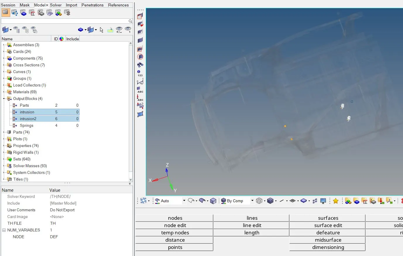
Intrusions
The diplacement of the specific node can be identified by opting for the intrusions parameter. In this node, for which the diplacement has to be claculated is specified.
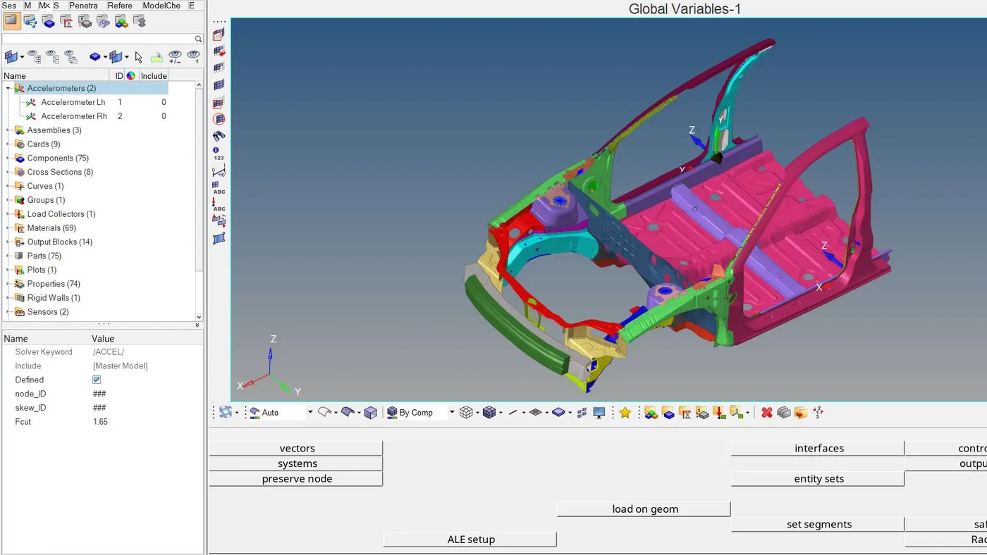
Accelerometer
After the instrusions, the accelerometer is created at the bottom of the B-pillar on both sides.
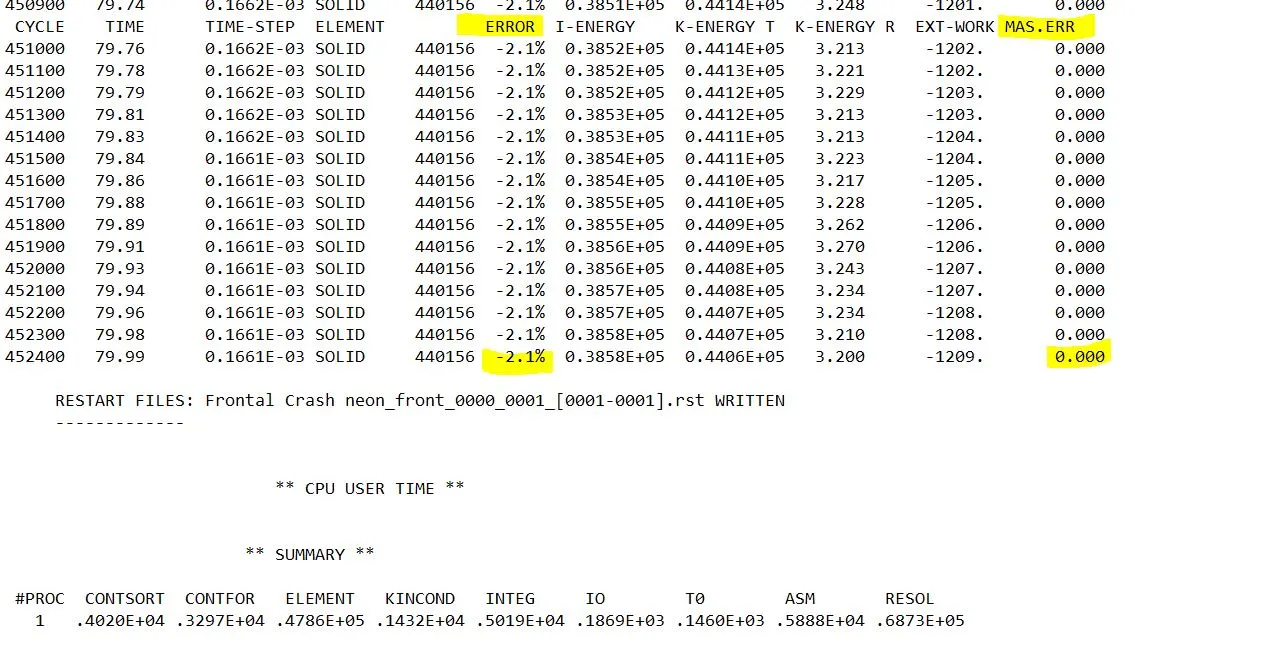
Energy error and mass error
Displacement
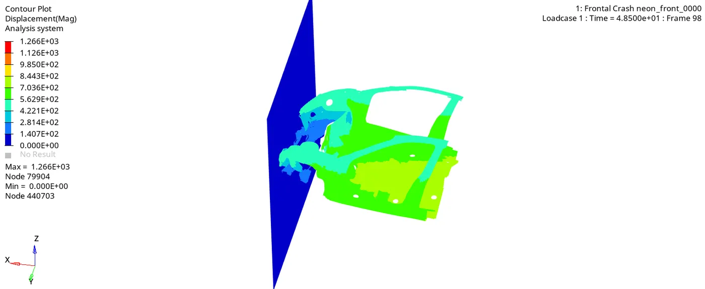
The maximum amount of displacment in the model is found to be 1266 mm at the 79904 node.
Von-misses stress
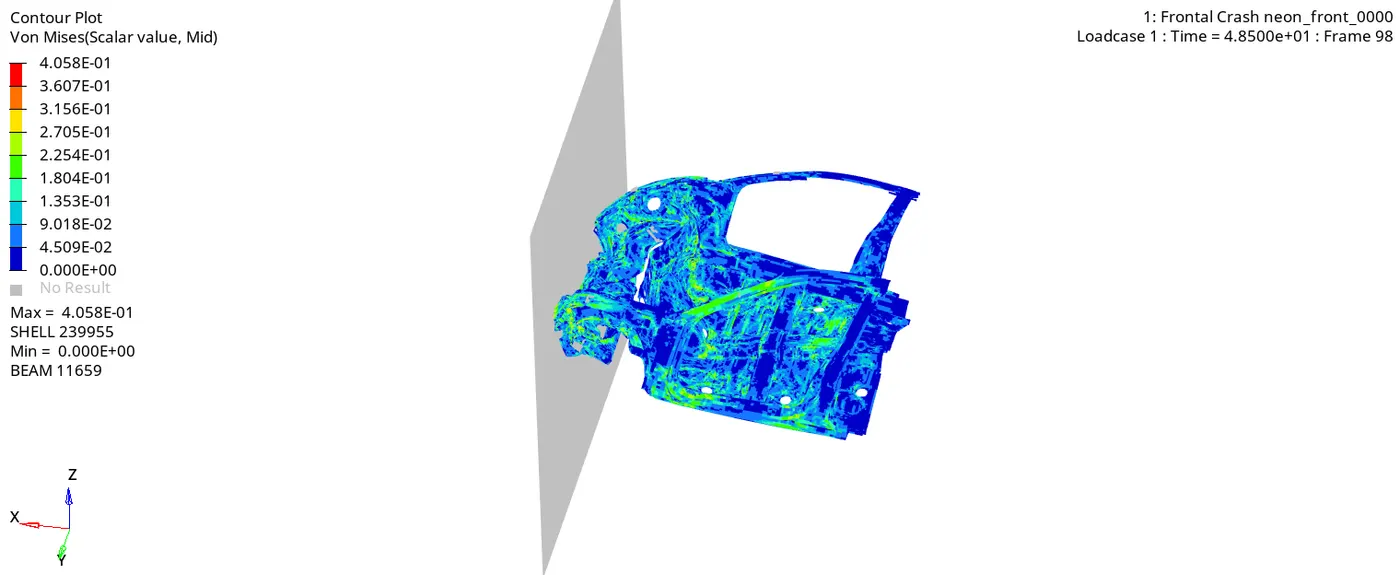
The maximum amount of stress in the model is found to be 0.4058 kN/mm^2.
Plastic strain
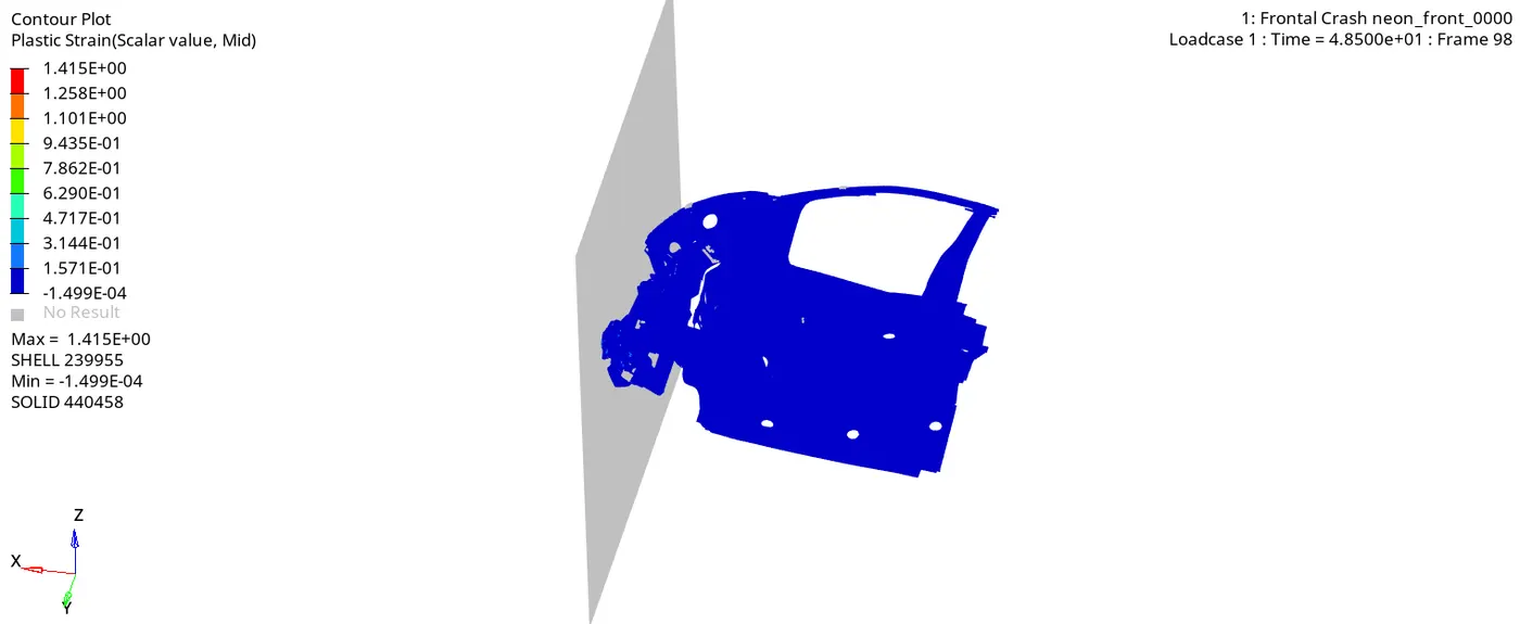
In hypergraph 2D, various energies and forces are analysed.
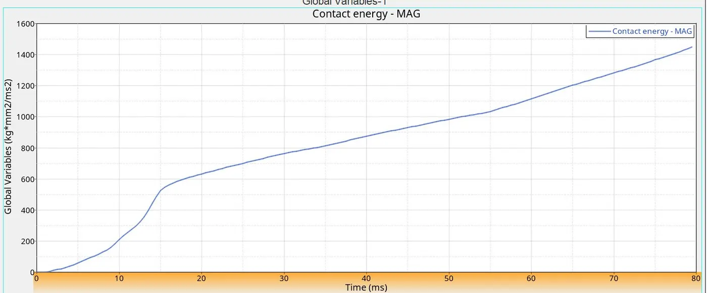
Result and conclusion
The maximum amount of energy is being absorbed by the crumple zone in the front portion. Due to this, only few amount of energy is transferred to passenger compartment. The sectional forces is plotted for created sections. It is understood from the project that most amount of energy should be absorbed before entering the passenger compartment.