Assignment 6
1) Types of turbocharger:
There are 5 types of turbocharger in practice.
(i) Fixed Geometry Turbocharger
(ii) Wastegate Turbocharger
(iii) Variable Geometry Turbocharger
(iv) 2 Stage Turbocharger
(v) E-Torbocharger.
(i) Fixed Geometry Turbocharger:
A Fixed Geometry Turbocharger is a simple turbocharger where no geomterical variations can be achieved according to the requirement.
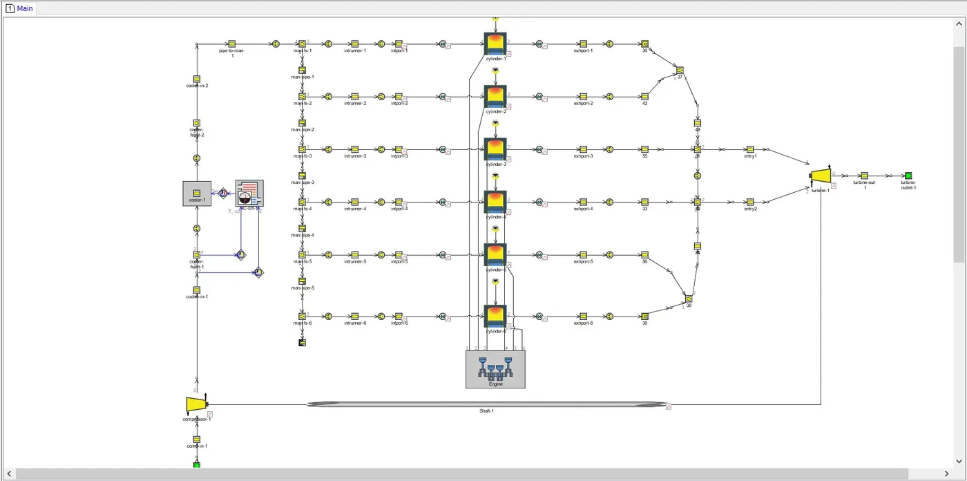
The above model can be found under File>Tutorials>Engine Performance>Turbocharging>Turbo_Step5-final.gtm
(ii) Wastegate Turbocharger:
A Wastegate Turbocharger provides a Bypass route to prevent the Turbine and Compressor from reaching extreme speeds that will lead to mechanical failure. It uses a mechanical diaphragm spring actuator to control bypass orifce diameter.
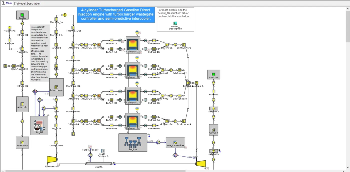
This example model is located under the following directory
File>Examples>Engine_1D_Gas_Exchange_Combustion>Gasoline>SI_4cyl_GDI_Turbo>SI_4cyl_GDI_Turbo-WOT.gtm
(iii) Variable Geometry Turbocharger:
A Variable Geometry Turbocharger uses Vanes that are controlled eletronically to reduce or increase the exhaust gas flow rate through the turbine. It helps in reducing Turbo-lag.
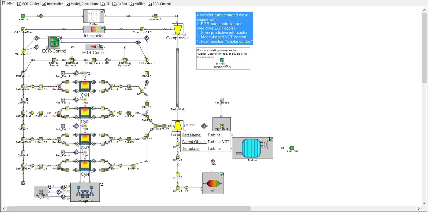
This example can be found under File>Examples>Engine_1D_Gas_Exchange_Combustion>Diesel>Diesel_VGT_EGR>Diesel_VGT_EGR.gtm
(iv) 2 Stage Turbocharger:
A 2 -Stage Turbocharger uses two compressors and turbines that are connected in series. This construction helps the engine to produce more power.
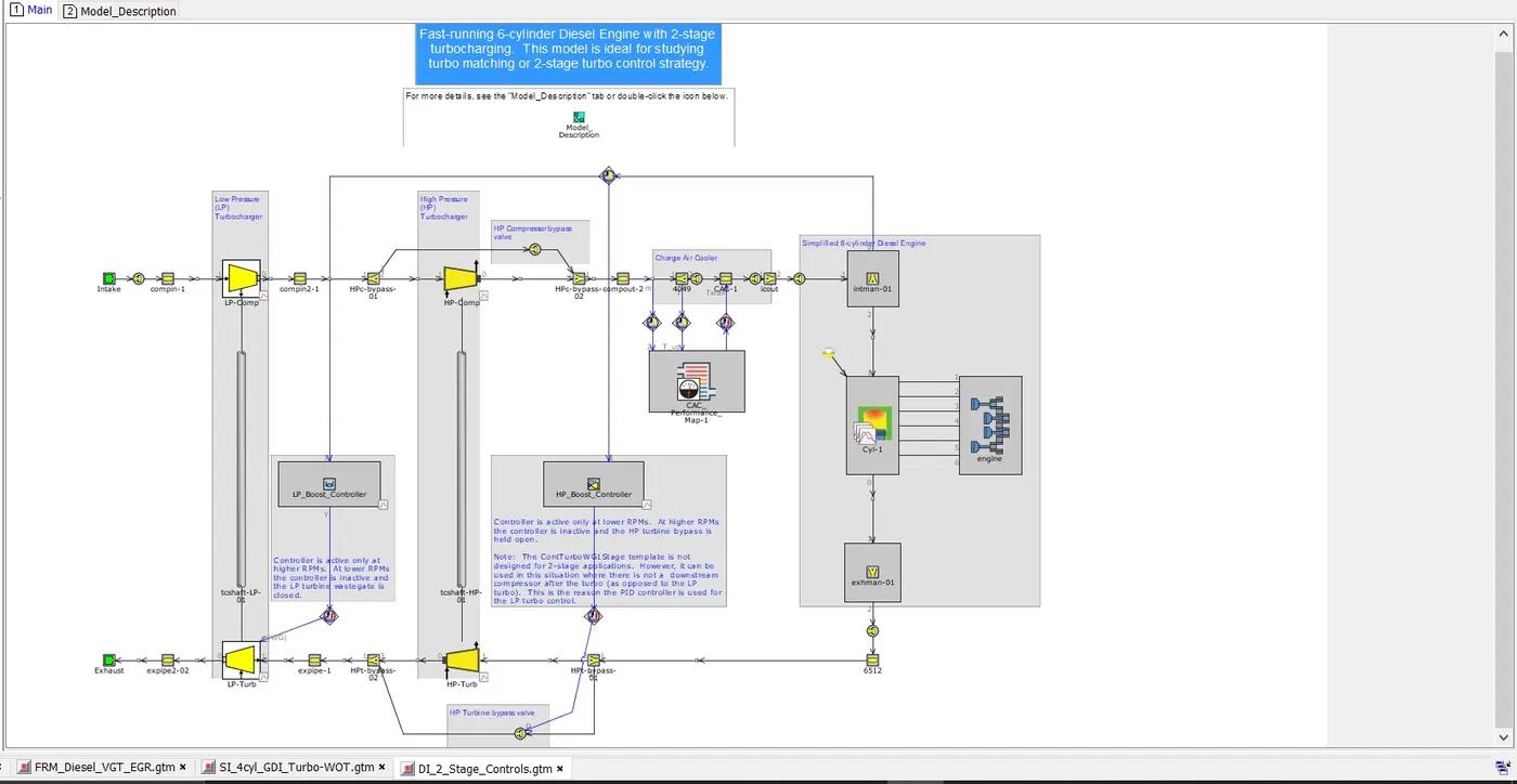
This model can be found under File>Examples>Engine_1D_Gas_Exchange_Combustion>Boosting>Turbo_Matching>DI_2_Stage_Controls.gtm
(v) E-Turbocharger:
This turbocharger helps in reducing Turbo-lag drastically. This type uses an electric motor to run the compressor before the exhaust gases reach the turbine thereby reducing Turbo-lag to almost zero.(I am not able to locate an example for this type of Turbocharger)
2)Explore Tutorial 6 & 7:
(i) Tutorial 6:
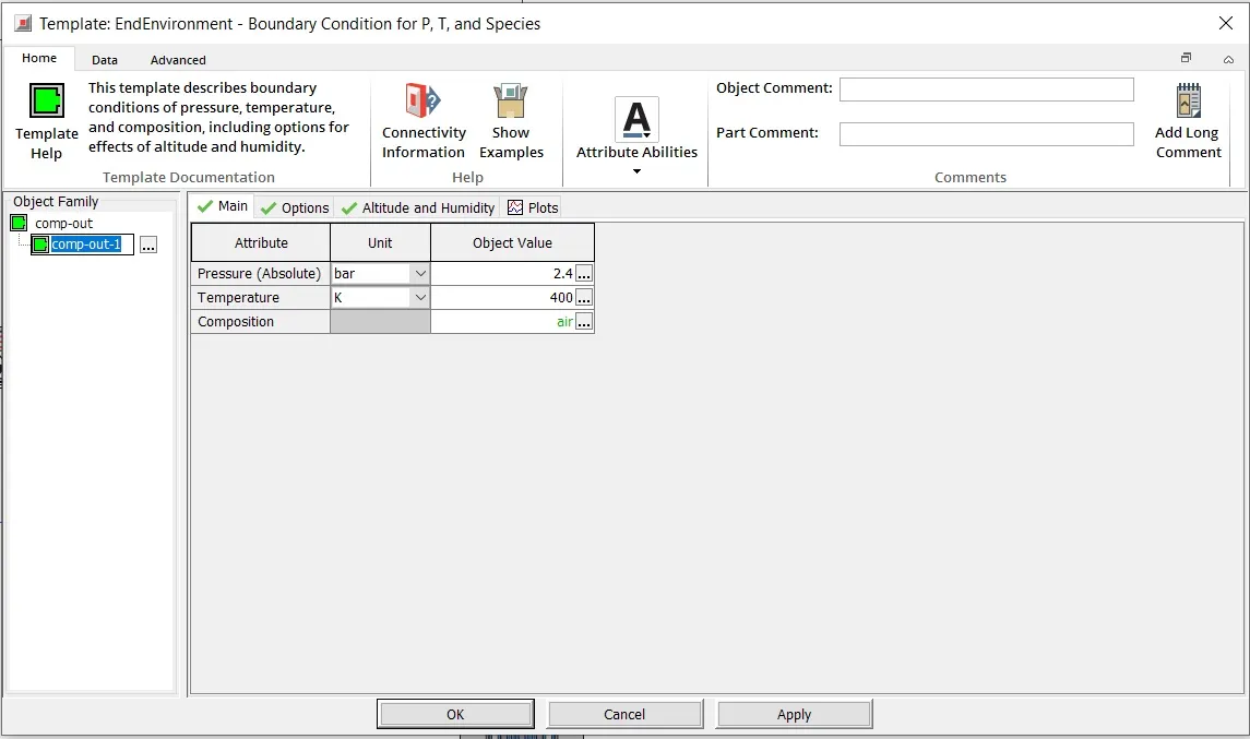
Below is the tutorial model. This model is a 6 Cylinder Naturally aspirated engine, but with high ambient inlet pressure.
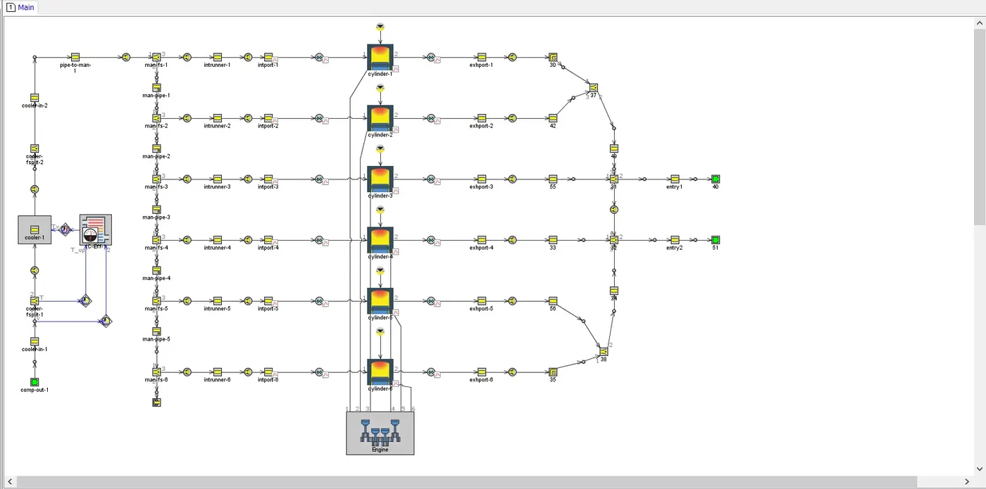
The following images provide details of the model
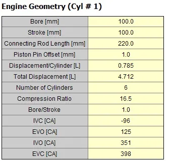
(a) Engine Geometry Specs: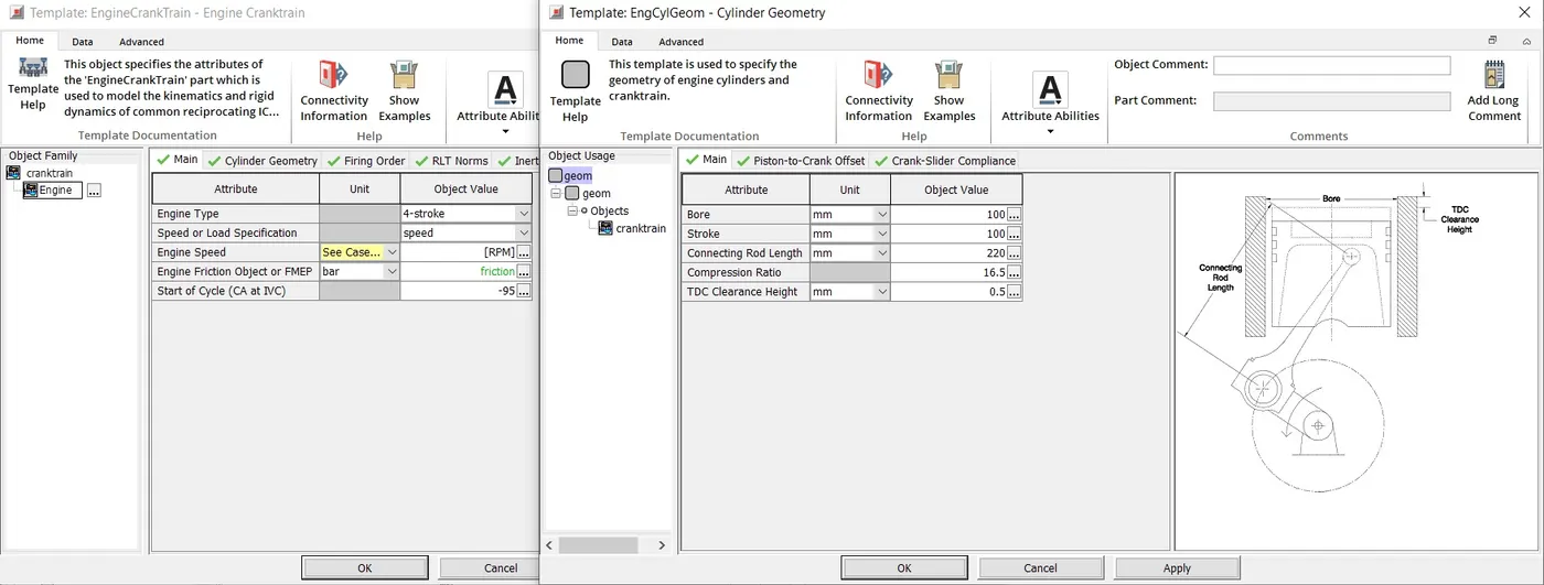
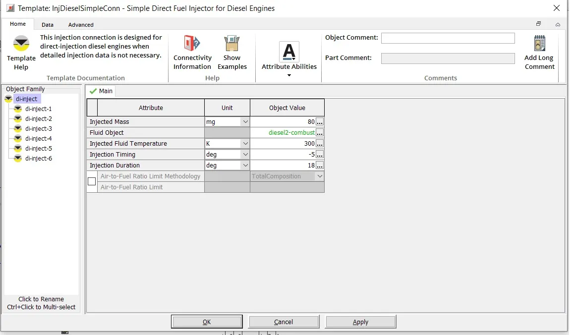
(b)Fuel Injector Specs:
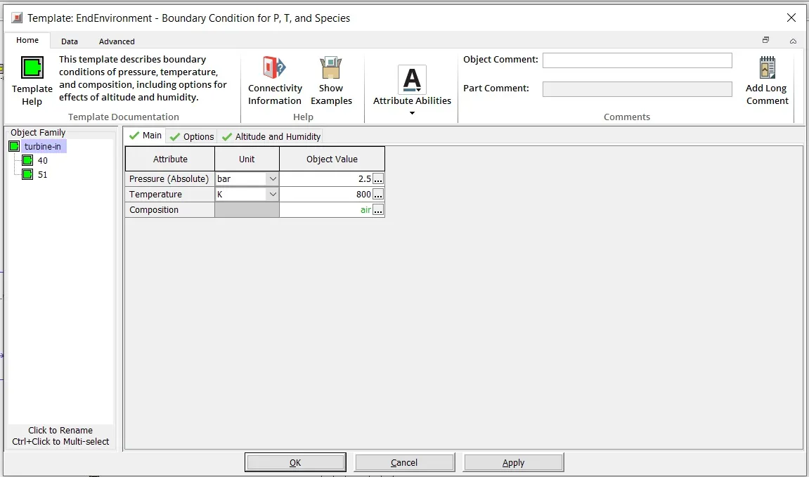
(c) Ambient Inlet & Outlet details:
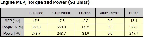
(d) Simulation Results:
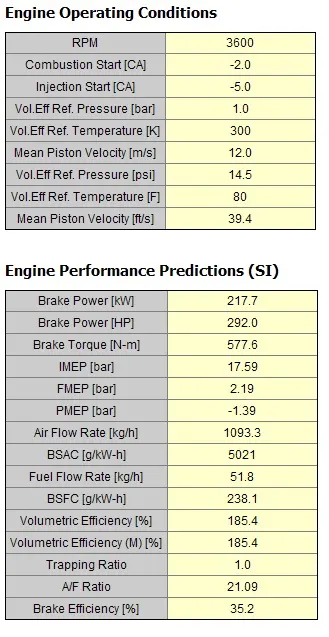
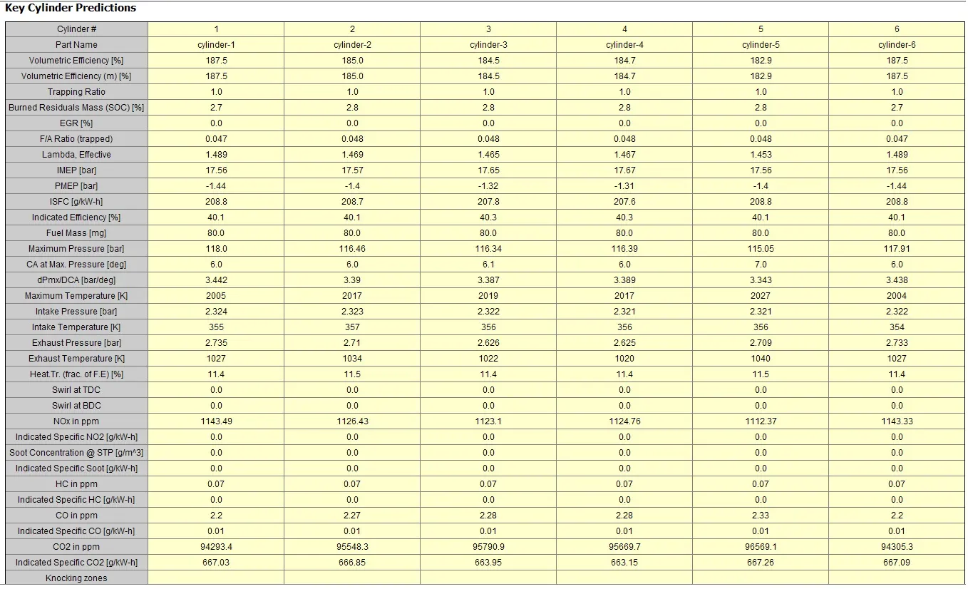
The model was run at 3600 rpm, which was the only written case. No other case was tried.
(ii) Tutorial 7:
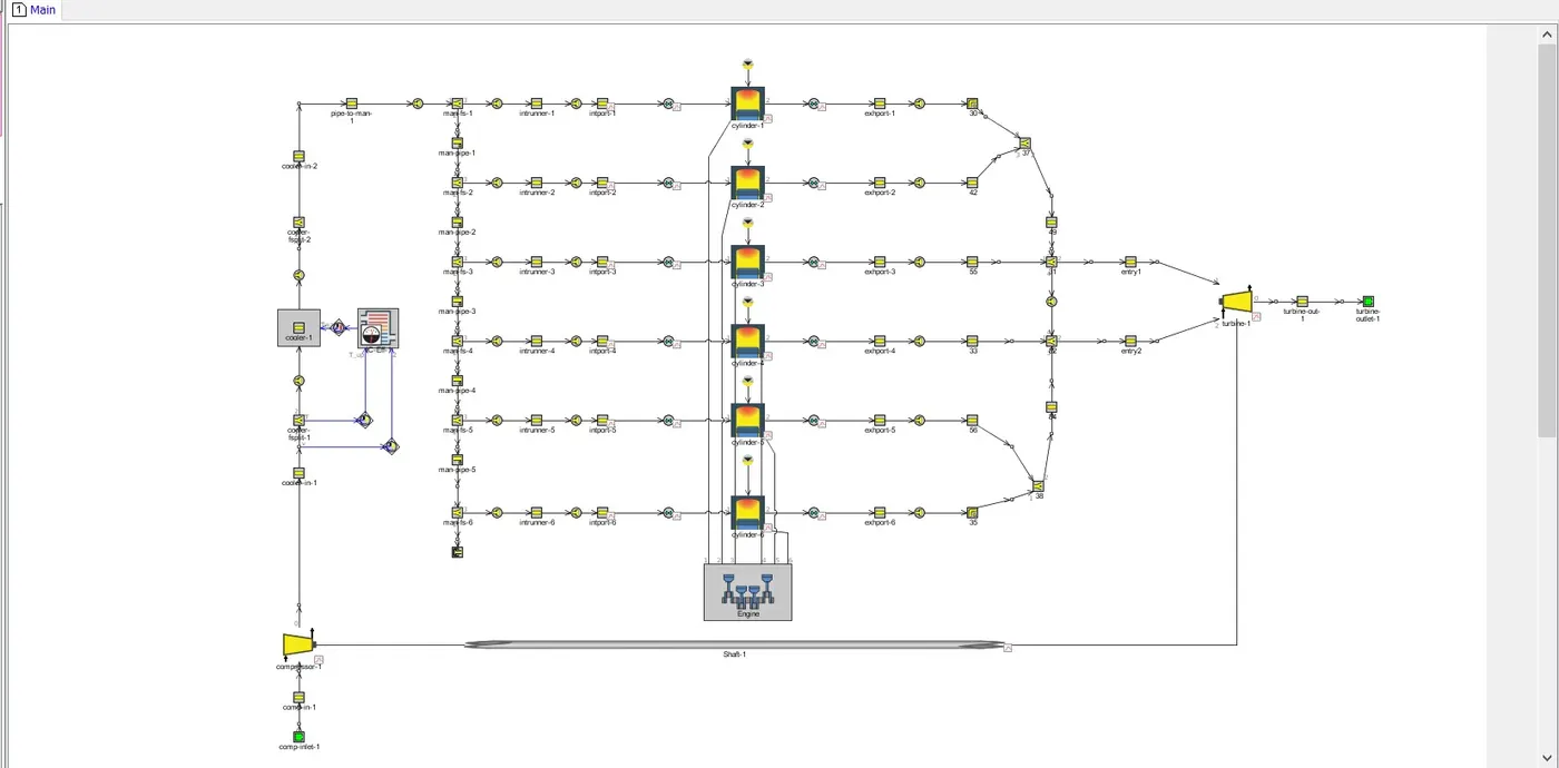
In this tutorial, it provides step-by step details for Turbocharger configuration. It includes 5 Seps in total. Below is the image that shows the model in Step 5
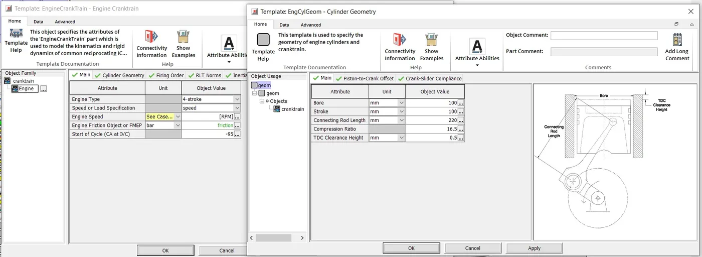
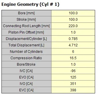
(a) Engine Specs:
(b) Injector Specs:
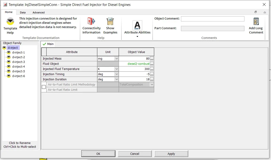
Upon comparing Injector and engine specs of tutorial 7 with that of tutorial 6, it can be noted that, both model uses the same specs for Injector and Engine.
(c) Ambient Inlet & Outlet conditions:
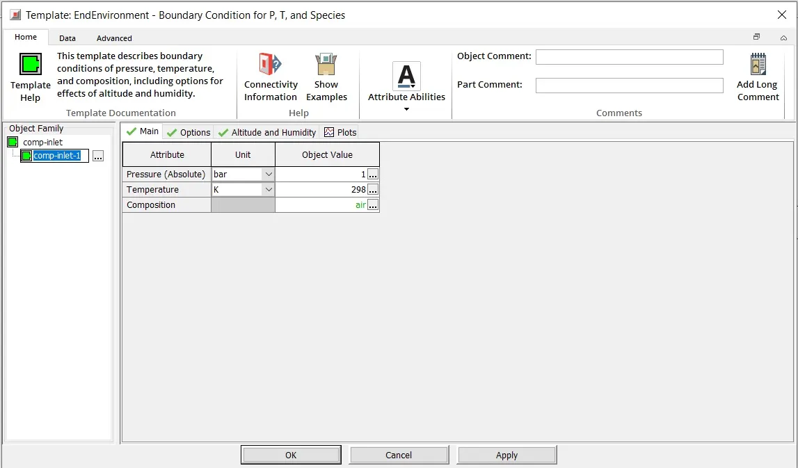
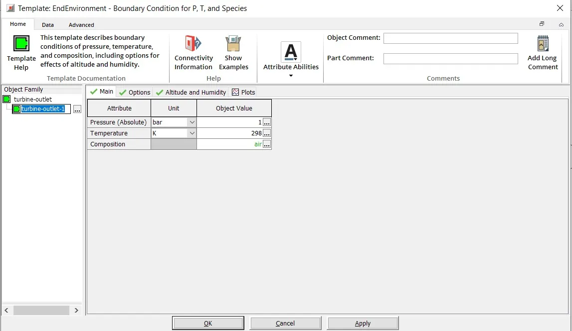
(d) Turbocharger Specs:
The following image provides the specs for turbine
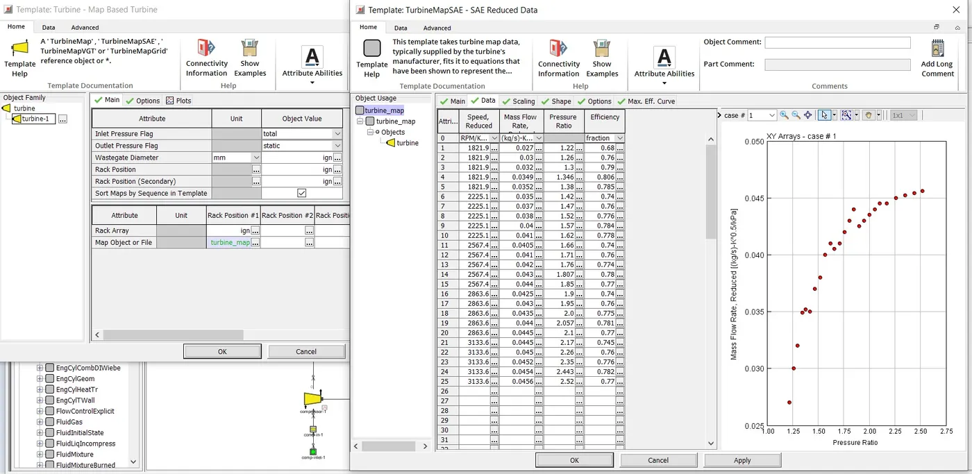
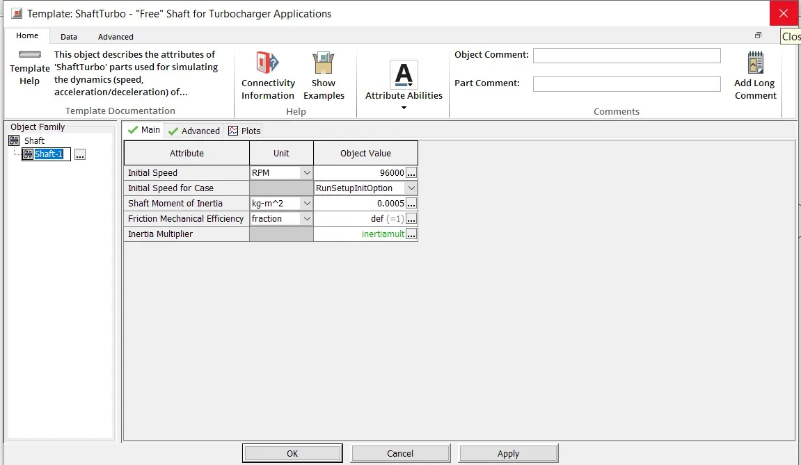
The next image provides specs for Shaft
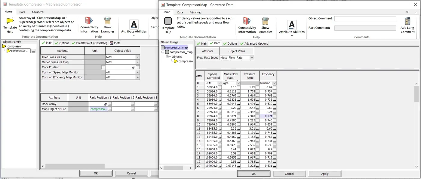
The last image provides details of Compressor
The above model was run at 3600 rpm which was already provided within the model case setup.
The following images shows the performance results.
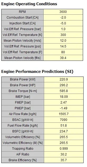
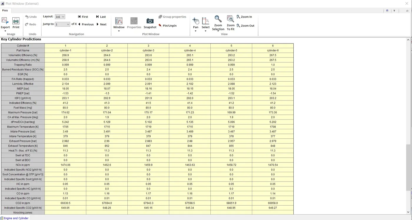
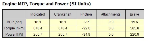
After comparing the performance results of the above model with tutorial 6, various differences can be observed. For example, the Brake Power has increased approximately by 3 kW and Brakke Torque has increased by approximately 8 Nm. Similarly various other performance changes is seen between the two models.
The next image shows the performance of Turboharger.
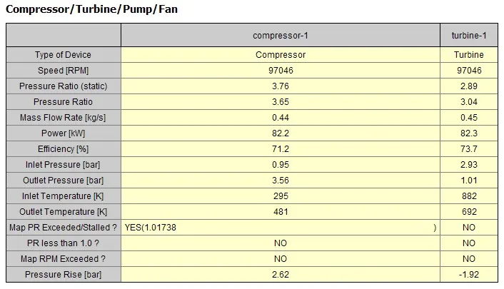
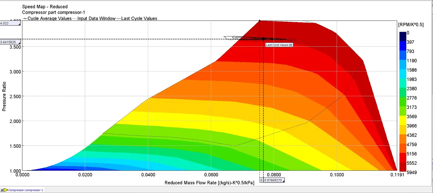
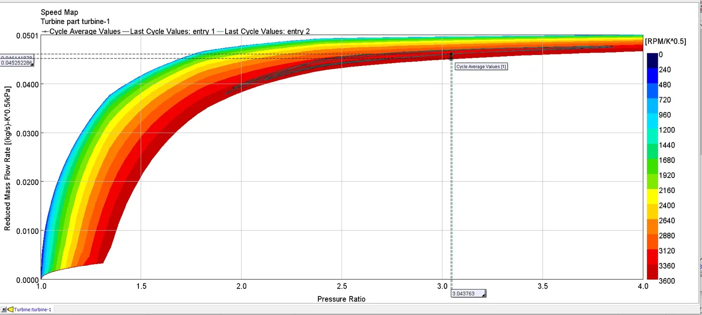
3) The following plots show the operating point of Compressor and Turbine that was obtained by doing simulation of Tutorial 7
Compressor Operating Point:
Turbine Opertaing Point:
4) Advantage of Variable Geometry Turbine:
Variable Geometry Turbocharger has lesser Turbo lag than a Fixed Geometry Turbocharger. Also when the engine is switched on the vanes can be adjusted to increase the exhaust gas pressure when flowing through the turbine, thereby reducing the the time taken for the Turbocharger to reach optimal Working Point. It also is useful for operating an engine at high altitude, where the ambient pressure is normally low. In this case, a fixed geometry turbocharger won't produce the required high density air that is reuquired to burn the injected fuel, which leads to efficiency losses. But, with VGT the vanes can be adjusted to run at high inital speeds and increase turbine and compressor speed which will compensate for the available ambient low pressure air.
5) Diesel VGT EGR:
The required model can be found by following the directory given below
File>Examples>Engine_1D_Gas_Exchange_Combustion>Diesel>Diesel_VGT_EGR>Diesel_VGT_EGR.gtm
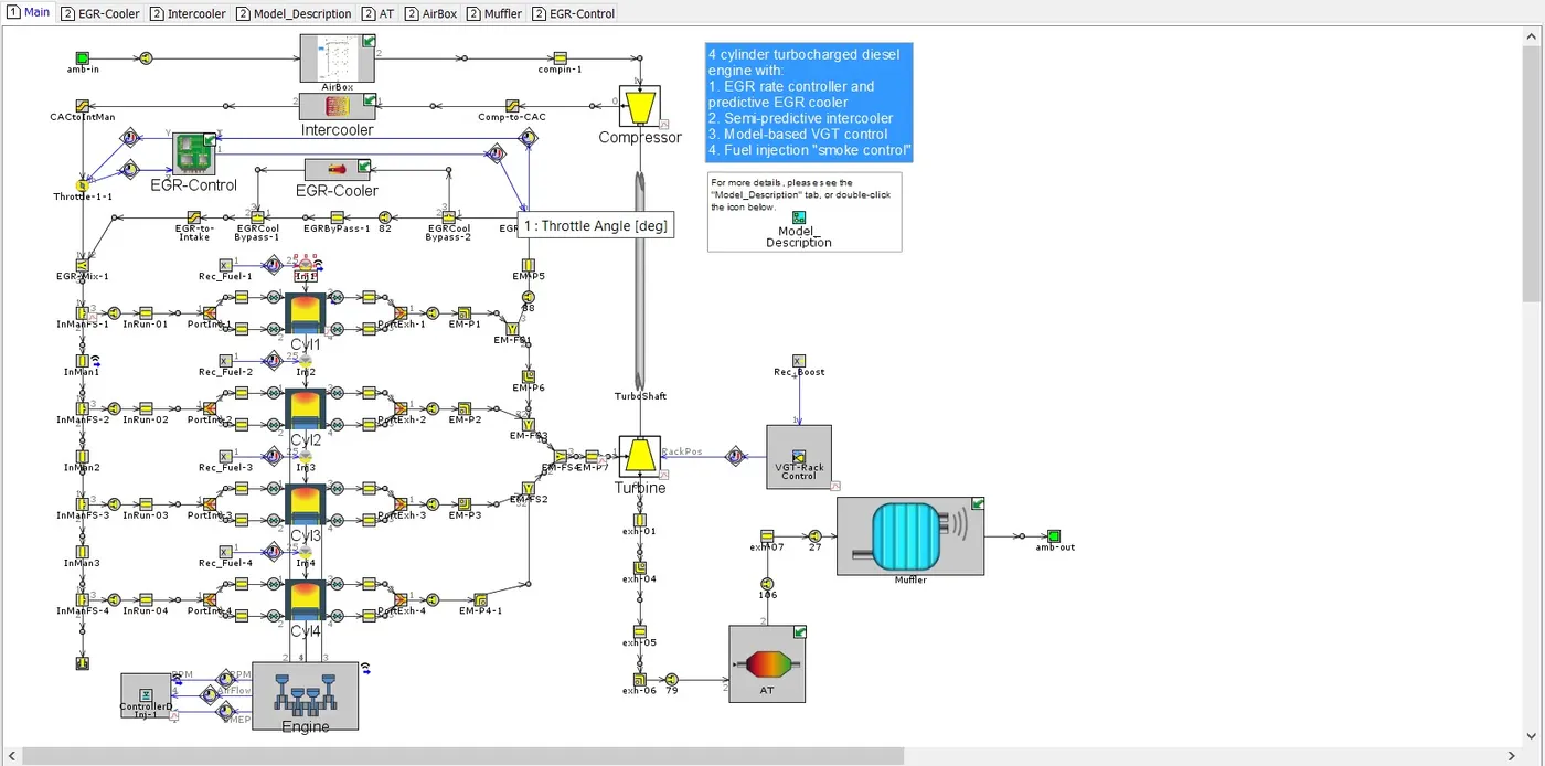
A detailed description about the model can be found under the "Model Description" tab. Some of the important details are described below.
(a) Engine:
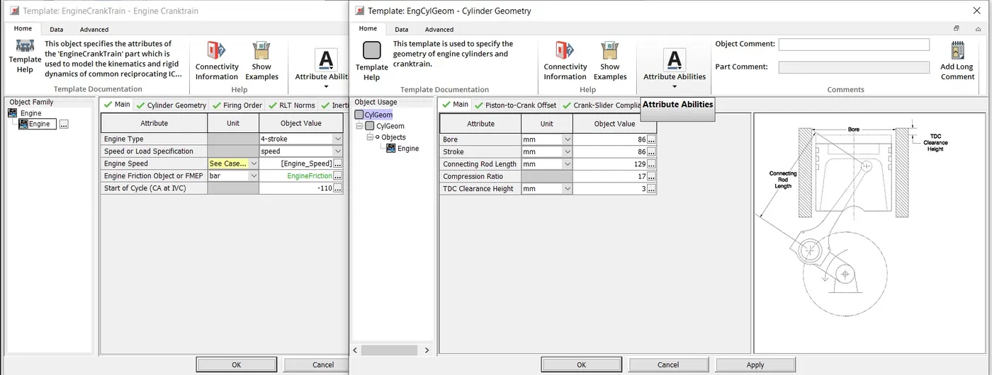
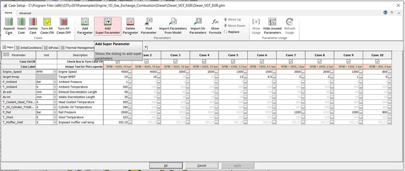
The engine is a 4 stroke, 4 cylinder, 2 litre engine with the above shown geometry specs. Combustion model used here is DIPulse method. Also predictive combustion method is used here. The engine will run at 10 different cases, out of which 6 different speeds are at full load, three are at part load and one is at idle speed. The image below shows the case setup.
(b) Intercooler:
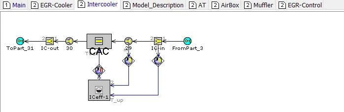
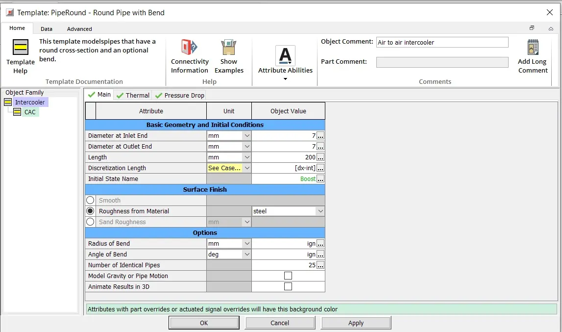
The Intercooler model and specs are shown above. This Intercooler runs on Semi-predictive method as the Heat Exchanger data is not available.
(c) Fuel Injection System:
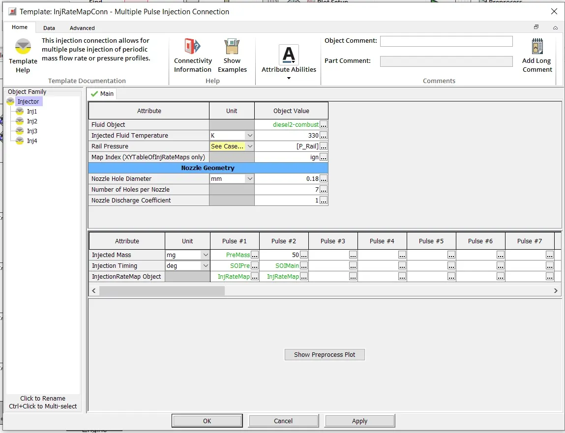
The injection method used here is Pulse injection system that is controlled by actuators which functions based on Engine speed and Pedal postion. This method is used here to prevent smoke production.
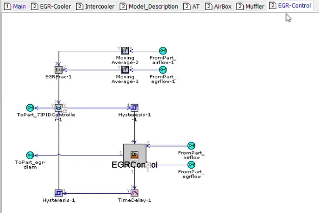
(d) EGR System:
An EGR is used to in this model to reduce pollutants by redirecting some amount of exhaust gases back to the intake manifold. This is poosible due to the pressure difference between intake and exhaust manifold. The EGR valve diameter is controlled using an actuator according to the requirement. In this model, the EGR is designed to allow a maximun of 40% of exhaust gases to be present in the Intake air.
(e) Turbocharger:
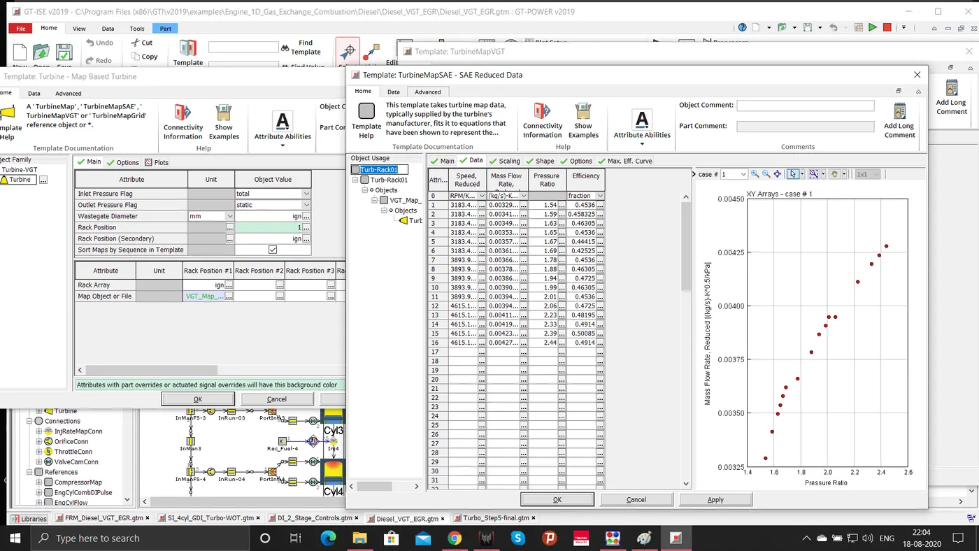
The above image shows one of the Turbine operating maps and specs.
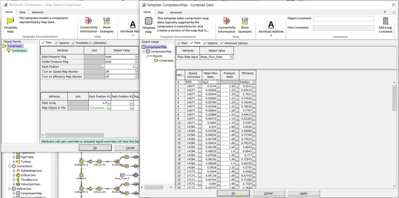
This image shows the specs and opertaing map of Compressor.
For Turbine, there are in Total 5 maps for various operating conditons. The rack or vane position is controlled by an actuator which is controlled by a controller unit.
With this I conclude my 6th Assignment.