Assignment 11
1) Simulation Results two different discretization lengths:
The single cylinder Diesel model was run with tow discretization lengths and the required comparisons are shown below.
(i) Simulation Time:
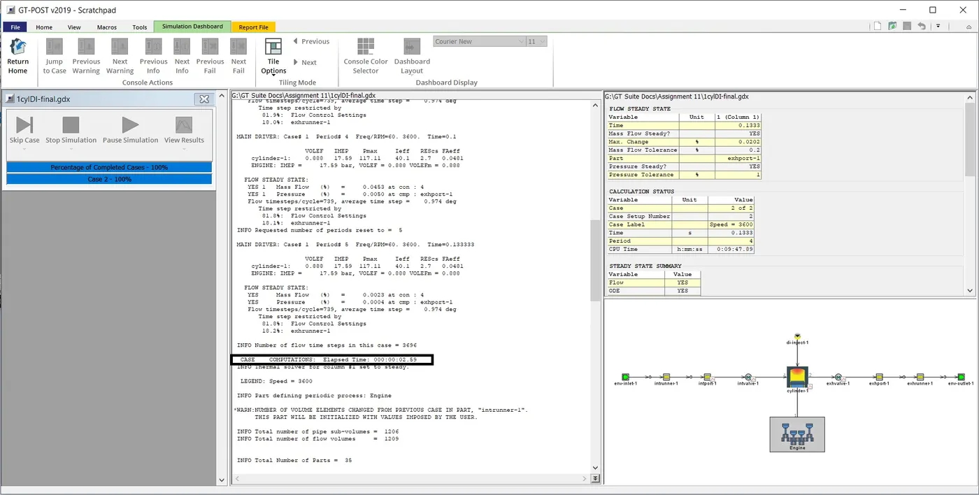
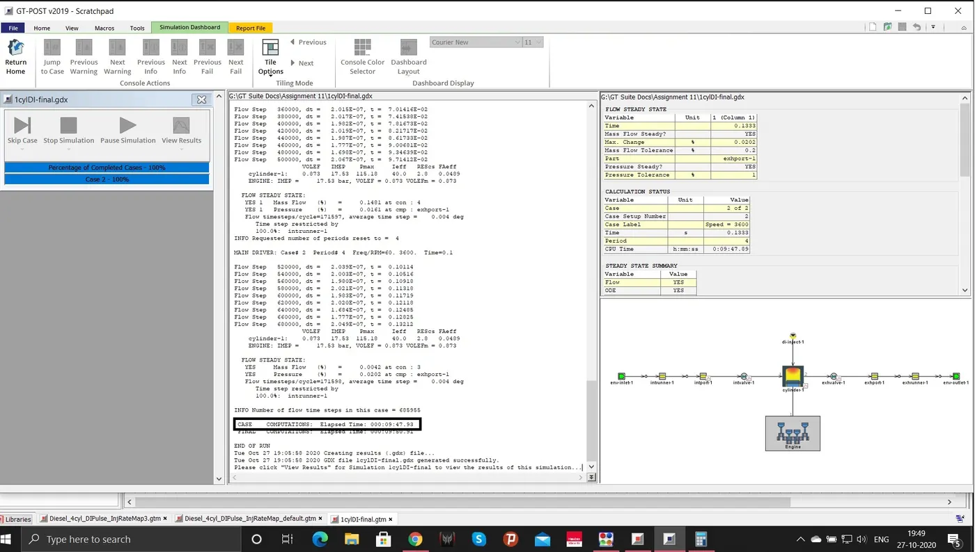
As seen in the image above, the simation time varies by a huge marigin. Case 2 with a discretization length of 0.1mm incresed the simulation time drastically.
(ii) Torque & BSFC:
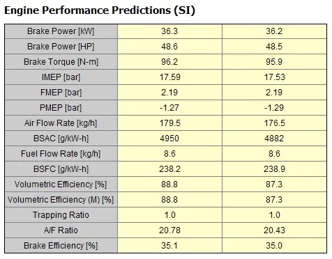
The difference observed is negligible when the difference in simulation time is considered.
(iii) Max In-Cylinder Pressure:
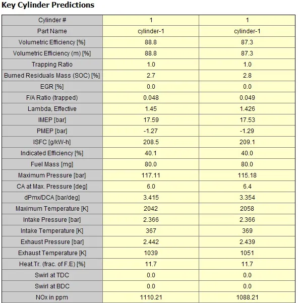
The same can be observed here. A difference of around 2 bar is identified.
2) Exploring Tutorial No.2. Discretizing Intake Manifold:
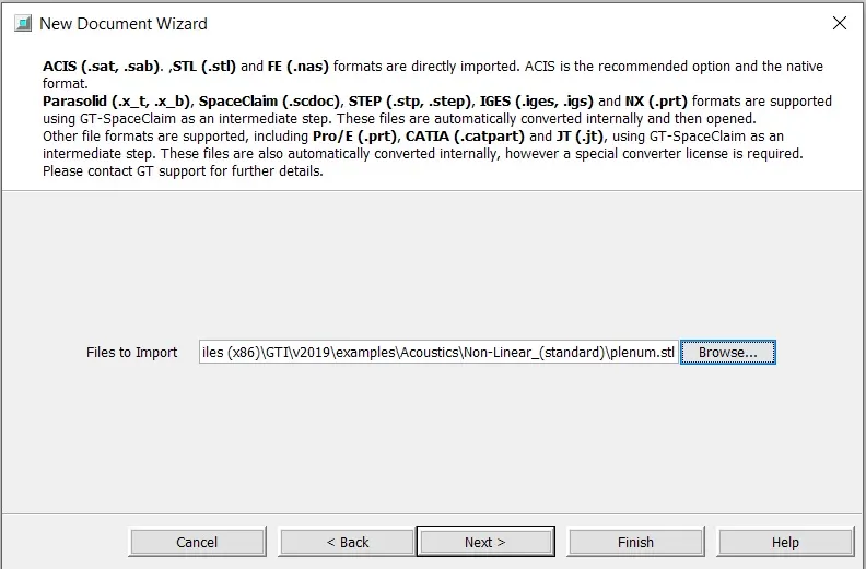
The first step involves importing a Shell from a STL file. It can be done by clicking import button at Home tab. The following dialog box appears where the required file can be chosen.
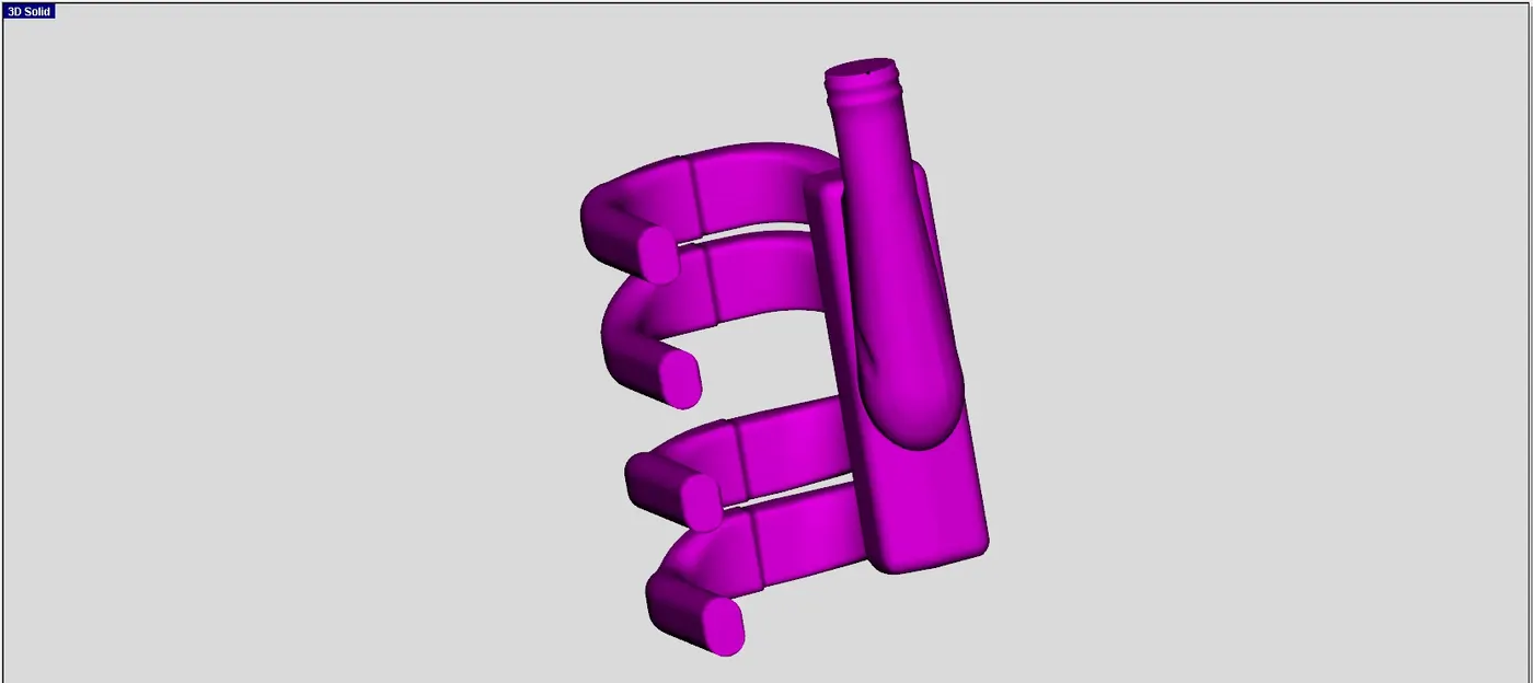
The Imported mesh part is shown below.
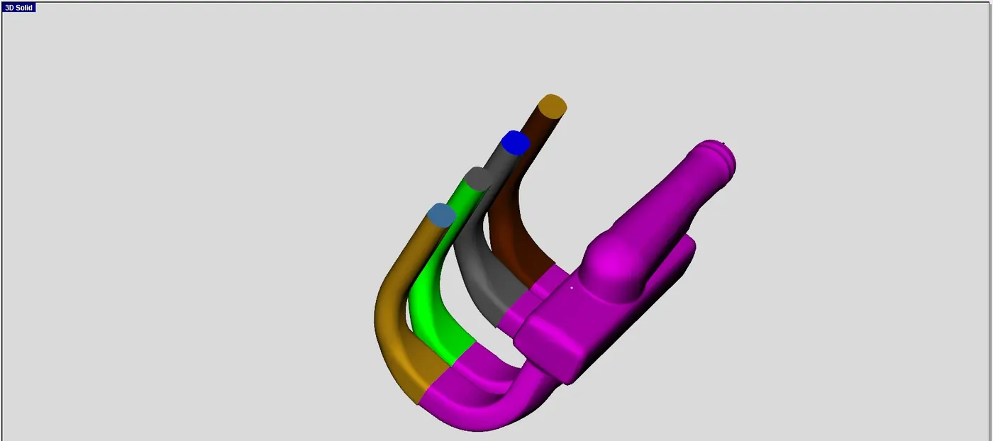
Next step invloves the process of cutting the above part using Seperate by Curves option which cuts the part automatically. The image shown below is result obtained after using the above mentioned option.
Next, the Intake and exhaust sides are made open. This is done by just selecting those surfaces and clicking delete.
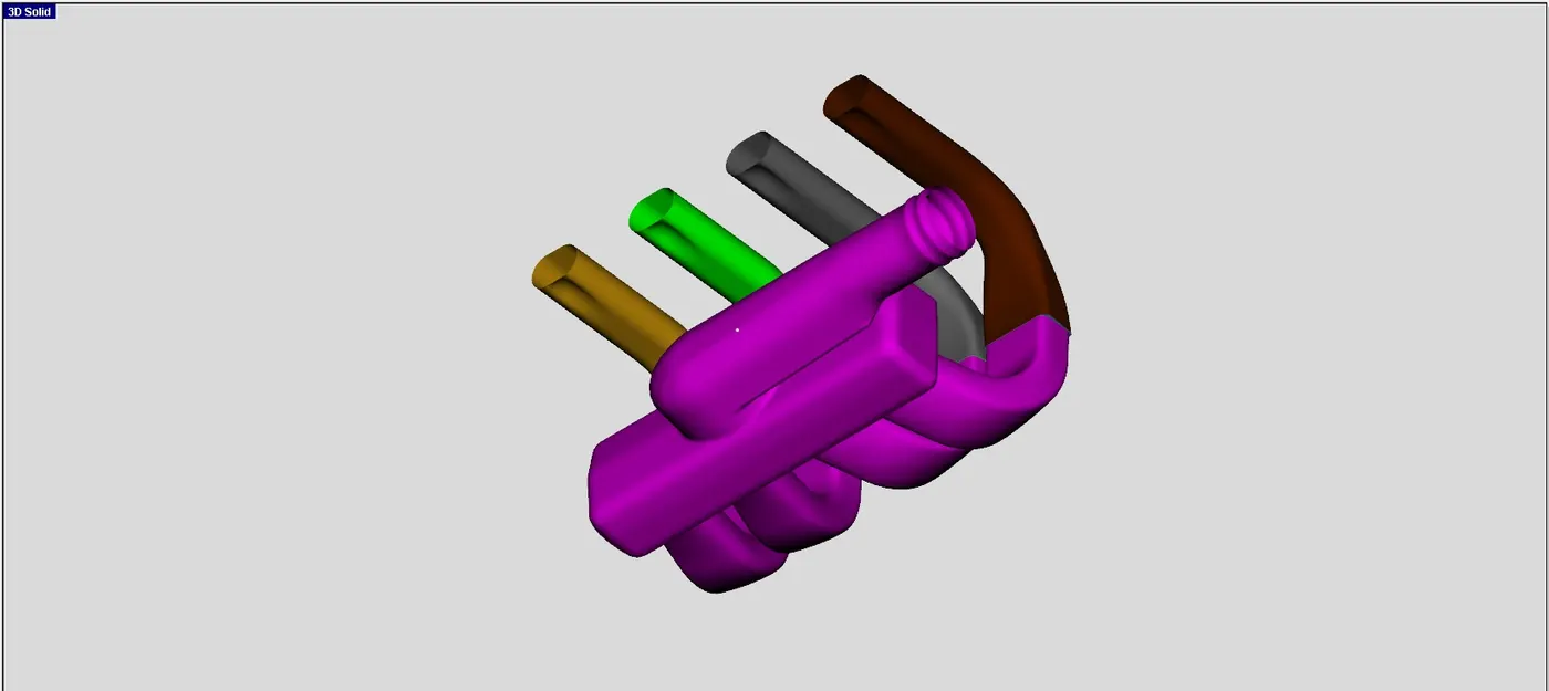
Next step is to seperate the intake runners from the manifold. This is done by using the three point cutting plane option. The result is shown below.
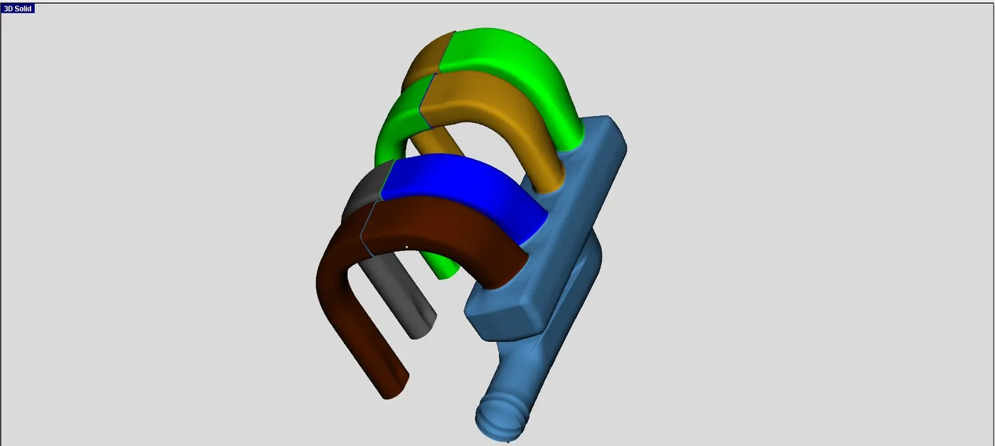
The runners are converted into flow component in the next step. This is done by right clicking a part and click convert shape to component option and following the necessary steps to complete the conversion. The pipe was chosen to be a pipe with multiple bends and the required data was entered in main and thermal tab. The process was contiuned for other three runners and the result is shown below.
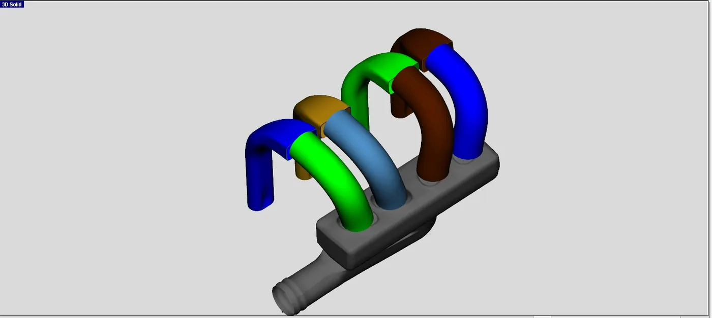
The same was done for second runners and the result is shown below.
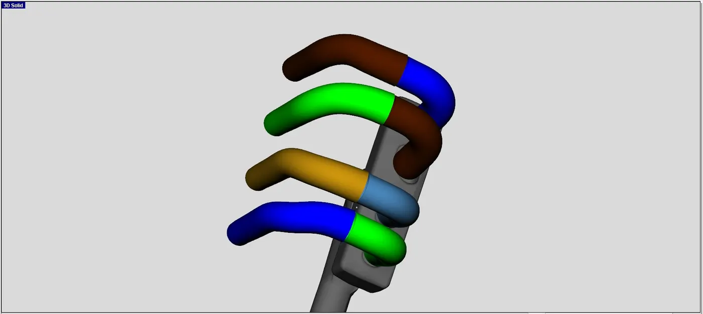
An orifice connection is to be added between runner and manifold. This can be done by right clicking a part and select add connection. This will open a window where an option will be provided to choose where the connection is required and the type of connetion that is required. Inorder to have smooth transition, 0.95 was used for forword coefficirent discharge.
For the outlet side, the option "GEMSubAssExtConn" is used at port 2 and the required data is entered in the follwing window.
The next step is to divide the inatake pipes. The intake pipe is seperated by using the option Pipe normal cutting plane and the result is shown below.
Next, the "d" shaped pipe is seperated from the manifold using three point cutting plane. The cut was done after postioning the cutting plane as required. The obtained result is shown below.
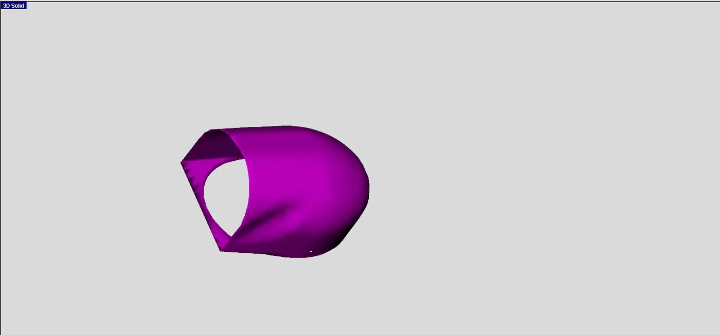
Next, the first two pipes are converted to components by following the same procedure followed for converting runners. The result is shown below.
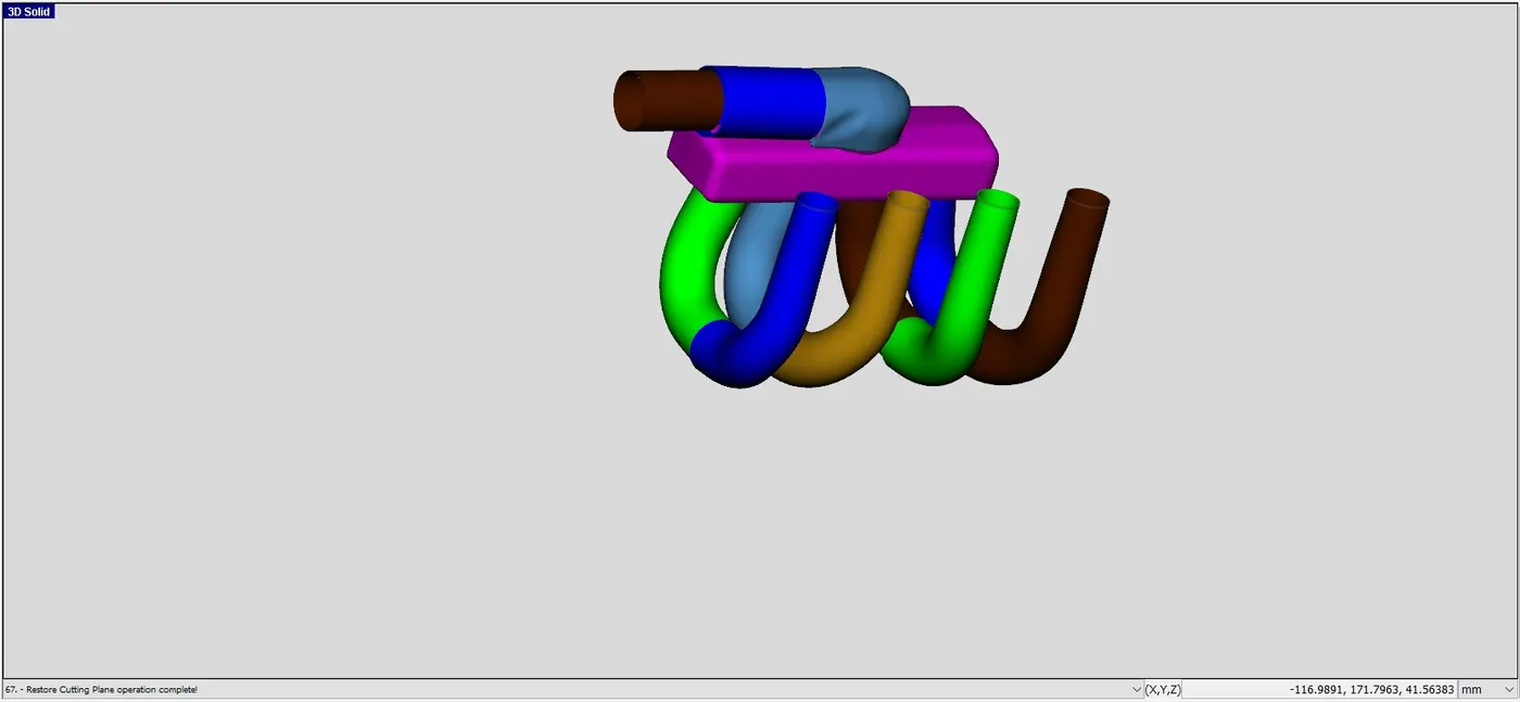
In the next step, the d shaped component is converted to a general flow spilt with default values.
Next, the manifold is cut into three different parts using three point cutting plane. The reult is shown below
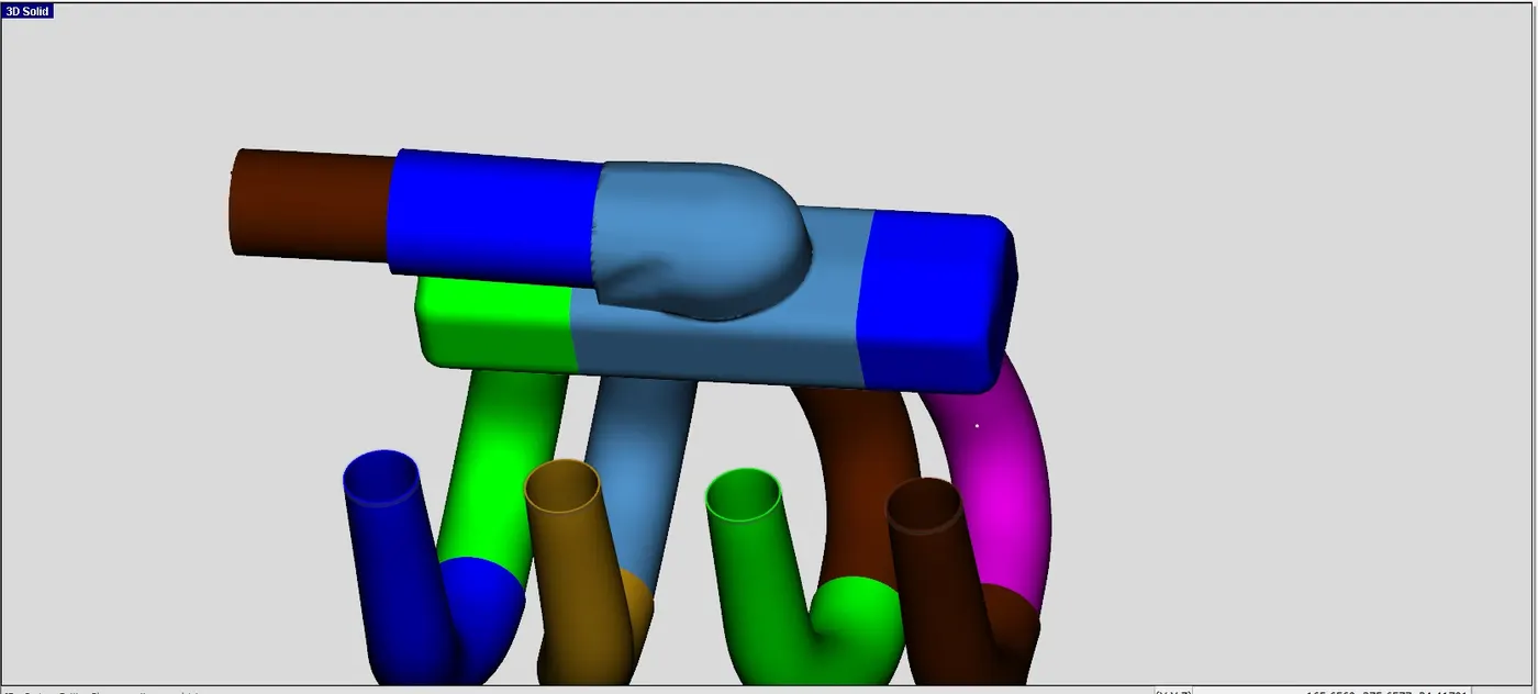
In the next step, these three components are further converted into general flow splits.
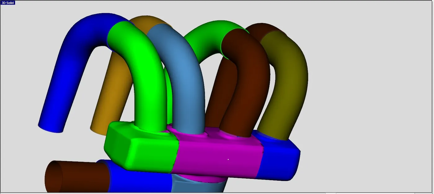
The next step involves adding flow conncetions between various joints using Flow Connection option under Flow tab. For flow connections between runners and manifold, extruded connection option is used. The result is shown below.
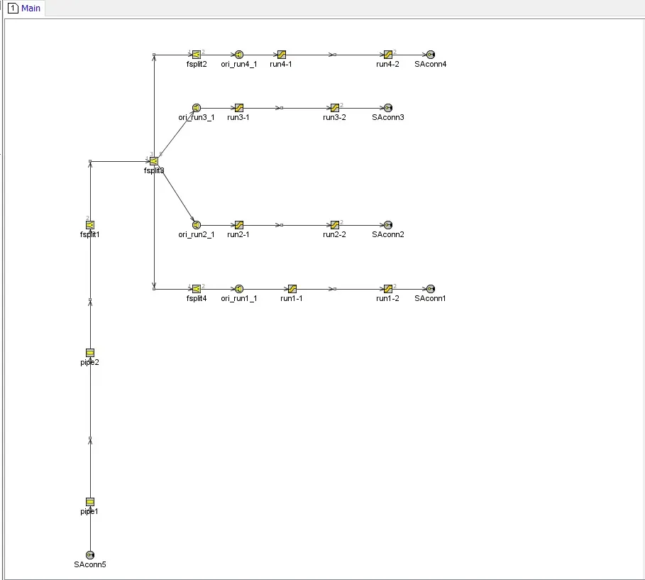
The next step is to dicretize the model. The model was postioned appropriately to avoid a messy conversion. The discretization lenght was set at 40 mm and the discretiztion was done. The 2d model was then arranged properly and the final model is shown below.
With this, I conclude my week 11 assignment.