Assignment 5-RADIOSS Interfaces & Study of Effect of Notches Challenge
Objective:
- To Create the mesh for bumper assembly of mesh size 6mm.
- To the given crash tube, Run the simulation as it is with provided interface properties.
- Change the Inacti = 6, run the simulation and compare the effect of Inacti w.r.t above case.
- Create the TYPE 11 contact and compare with TYPE 7 contact.
- Comparing the results obtained with notch and without notch and how does the notch is affecting the results.
Bumper Meshing:
Given model:
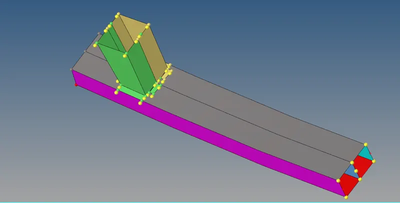
Clean-up the geometry before meshing
Go to Geometry >>> Temp nodes >>> clear all
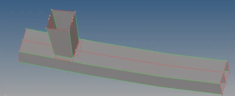
We can see lot of single cons representing no connection b/w parts.
Connect the parts using extend in surface edit.
After clearing all the geometrical errors, Mesh the model using 2D module >>> Mesh with size of 6mm.
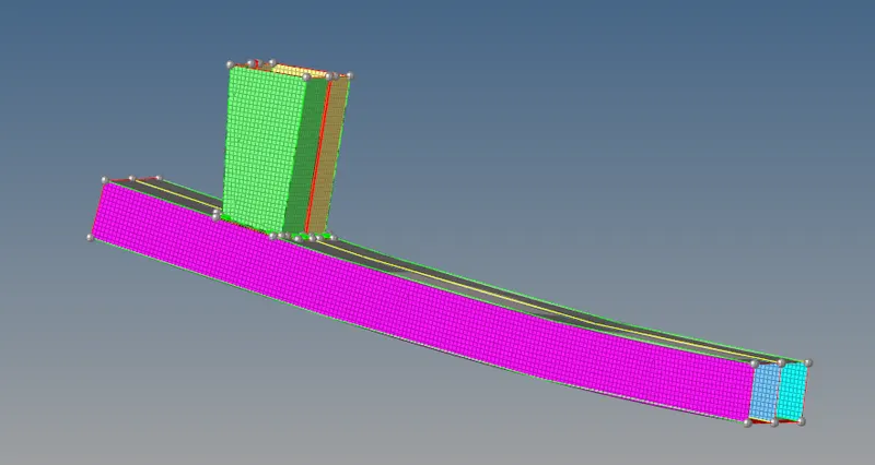
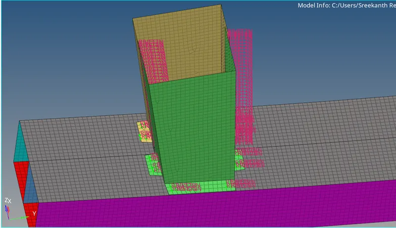
We have to make respective connections using spot or seam weld.
Go to 1D >>> Connectors >>> Spot >>> Selct the nodes >>> Select components >>> Type as weld >>> Create.
Interfaces & Study of Effect of Notches:
Interfaces are defined to model, how parts interact when they come into contact with each other.
There are two terms defined when interactions are happening: Slave and Mater.
Master is going to tell how the slave behaves. Generally, Master is rigid. Slave obeys the motion imparted by the master node.
Interface Penalty Method:
Most commonly used for crash analysis, this method treats the behaviour between master segment and slave nodes as spring that receives resistive forces as a function of penetration.
Spring elements are created b/w slave nodes and its projection.
The coarser the mesh, stiffer the structure will be, provided the material and structural properties are same. Master is generally meshed coarser so that the slave doesn’t penetrate master that is why we choose less deformable or higher stiffer structure as master and less stiff as slave.
Body under analysis is slave, when we want to study forces and stresses.
Interface parameters:
Igap: Determines how the size of gap is calculated.
Gapmin: Minimum gap for activation of interface.
Inacti: Action to take if initial penetration exists.
Istf: Affects how the stiffness of interface is calculated.
Iform: Friction formulation.
Stmin: Minimum stiffness to use in the interface.
Idel: To decide the behaviour of nodes during failure.
Case 1: Run the crash tube model as it is.
Interface properties:
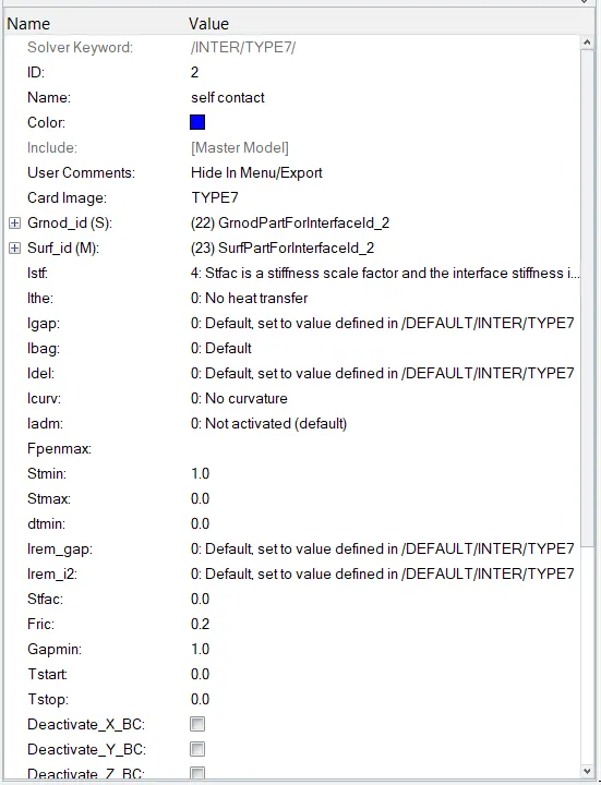
Interface TYPE7 is a multi-usage impact interface, modeling contact between a main surface and a group of secondary nodes.
Go to Analysis >>> Radioss >>> Save as >>> Options: -nt 4 >>> Enable include indicators >>> Run.

Radioss simulation is performed and the results are obtained.
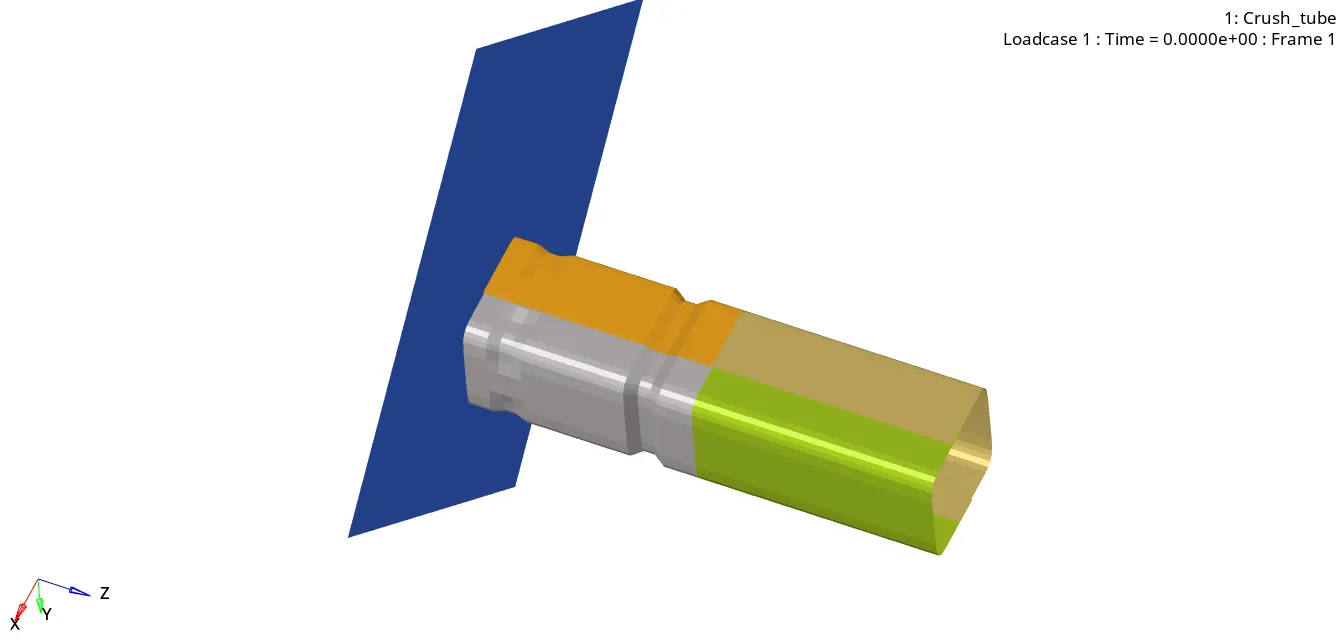
For the animation files use the A00 files or h3d files.
For the Plotting of graph, use time history files.
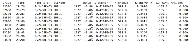
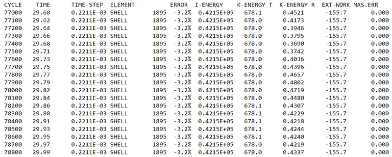
Total number of cycles = 83469
Total run time = 85.67s
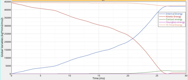
Max.Internal Energy = 42020 J
Energy error is -3.8%.
ENERGY plots:
- Contact Energy:
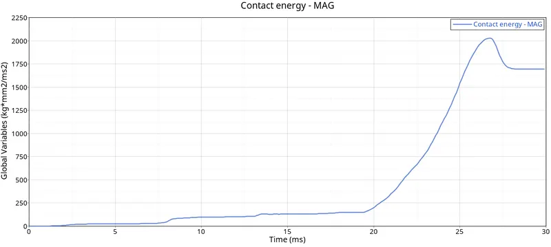
Explanation:
When friction is included in contact defination, Friction should result in positive contact energy.
In absence of friction, we see small net contact energy as sum of slave node energy and master node energy, small net means 10% of net internal energy in absence of friction.
The maximum contact energy = 2000J
- Internal energy, Kinetic energy, Hourglass energy, Total energy:
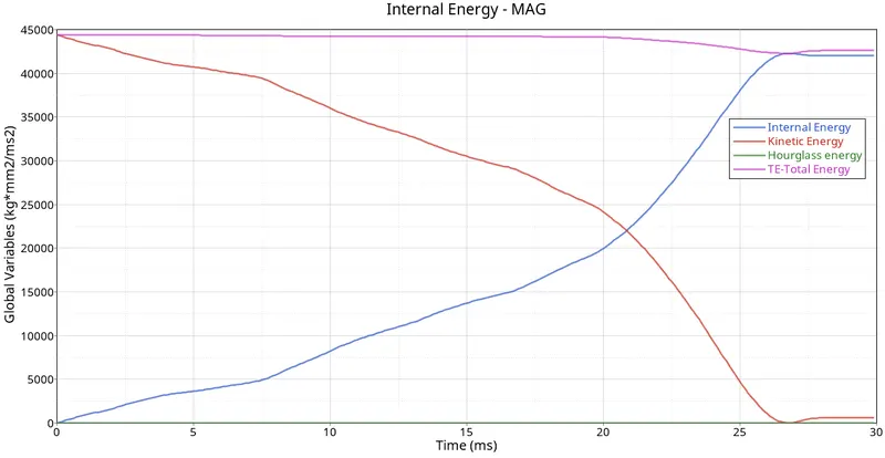
Explanation:
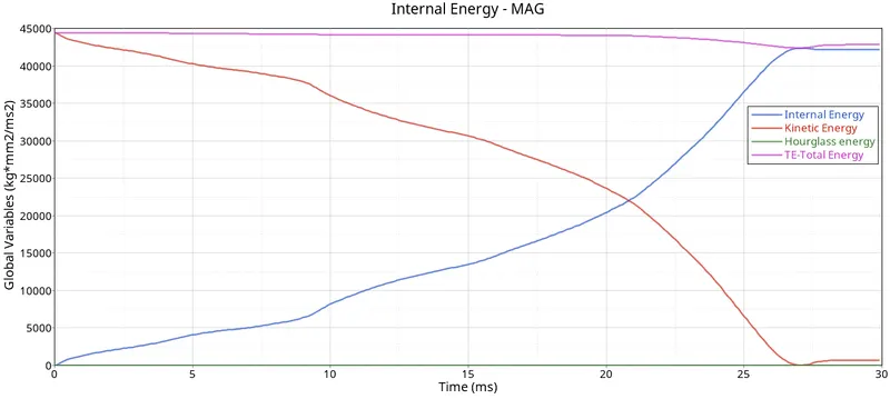
Hourgalss ennergy is zero w.r.t time due to the application of recommended properties.
Kinetic energy at the start of application of load is very high due to high velocity, and it decreases there on as deformation reaches to maximum value.
internal energy increases as the deformation is taking place.
Total energy, which is sum of K.E and I.E is almost constant at 45000J
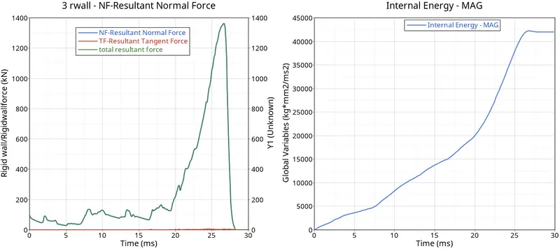
- Contact forces, Von Mises Stress:
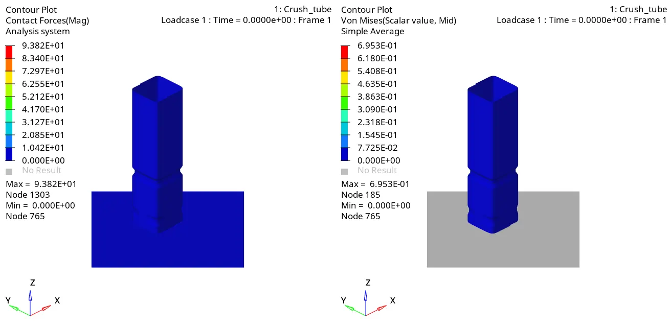
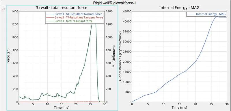
Explanation:
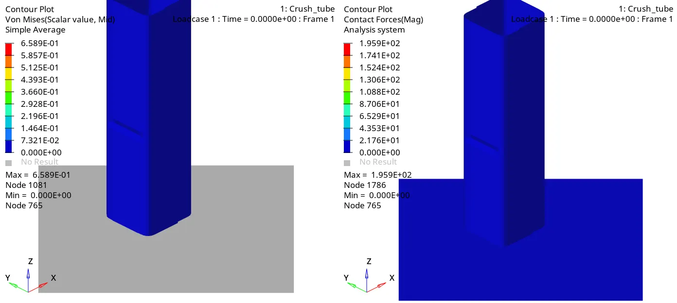
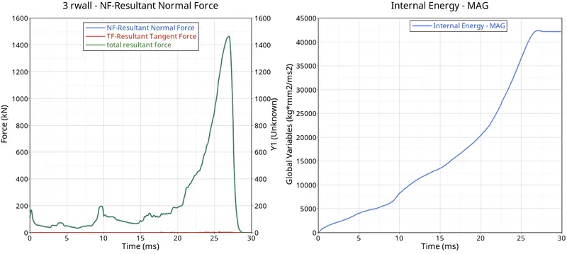
A rigid wall is an idealization of a solid body in which deformation is neglected. A rigid wall is a nodal constraint applied to a set of slave nodes in order to avoid the penetration to the wall. If contact is detected, then the slave node Velocity and Accelaration are calculated.
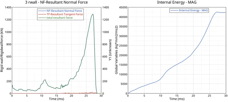
The maximum internal energy is 40000J
The maximmum rigid wall force after the crush tube is impacted on rigid wall is 1300 KN at t = 26 ms.
Case 2: Change the Inacti=6 and run.
Interface card:

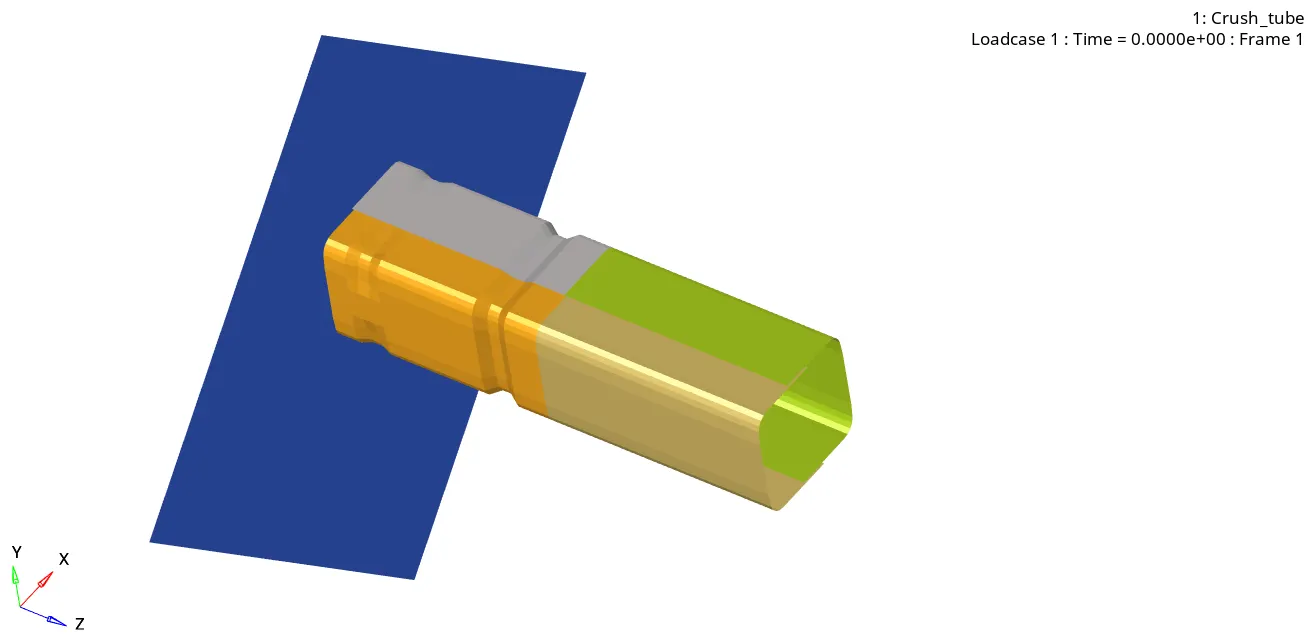
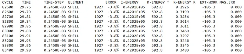
Total number of cycles = 83400
Max.Internal Energy = 42020 J
Energy error is -3.8%.
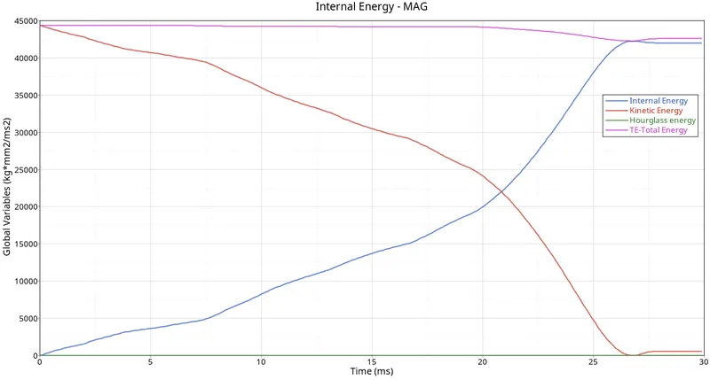
Hourgalss ennergy is zero w.r.t time due to the application of recommended properties.
Kinetic energy at the start of application of load is very high due to high velocity, and it decreases there on as deformation reaches to maximum value.
internal energy increases as the deformation is taking place.
Total energy, which is sum of K.E and I.E is almost constant at 45000J
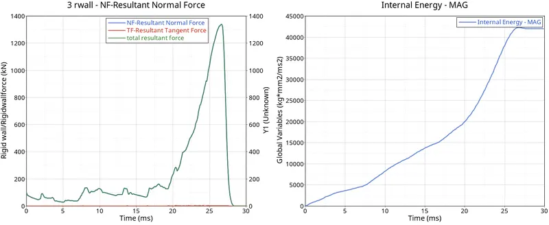
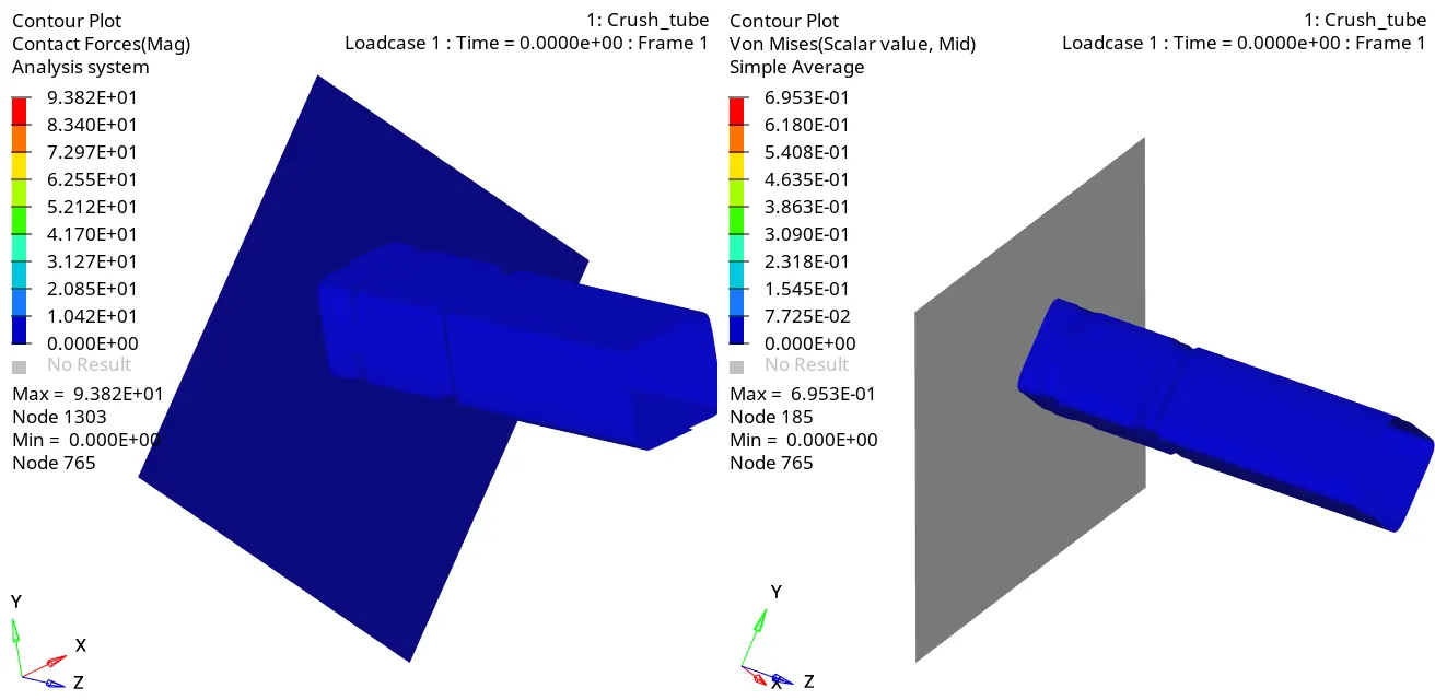
A rigid wall is an idealization of a solid body in which deformation is neglected. A rigid wall is a nodal constraint applied to a set of slave nodes in order to avoid the penetration to the wall. If contact is detected, then the slave node Velocity and Accelaration are calculated.
The maximum internal energy is 42500J.
The maximmum rigid wall force after the crush tube is impacted on rigid wall is 1300 KN at t = 26 ms.
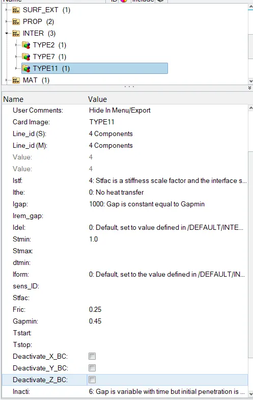
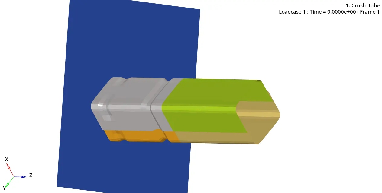
Case 3: Create the type 11 contact and run.
Case 4: Remove both notches and remove boundary condition on rigid body node then run.
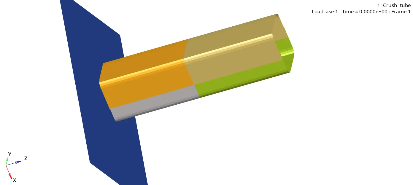
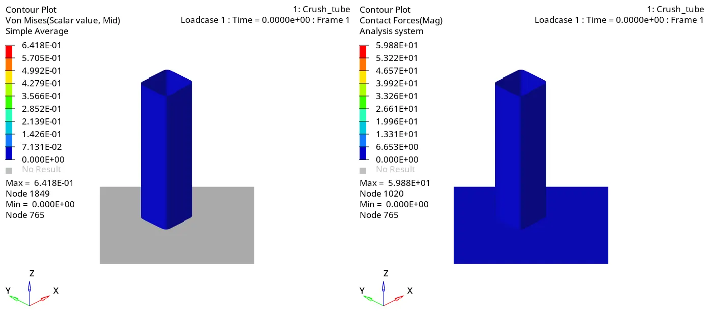
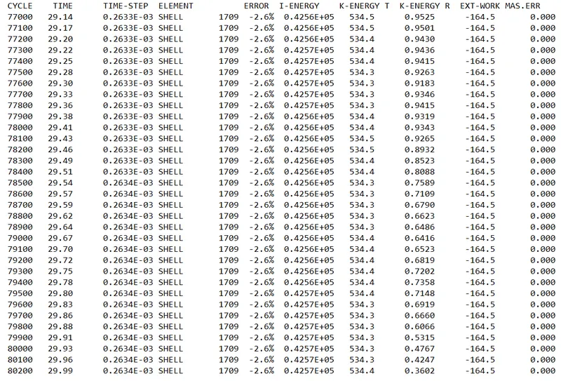
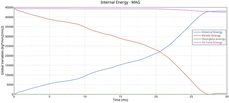
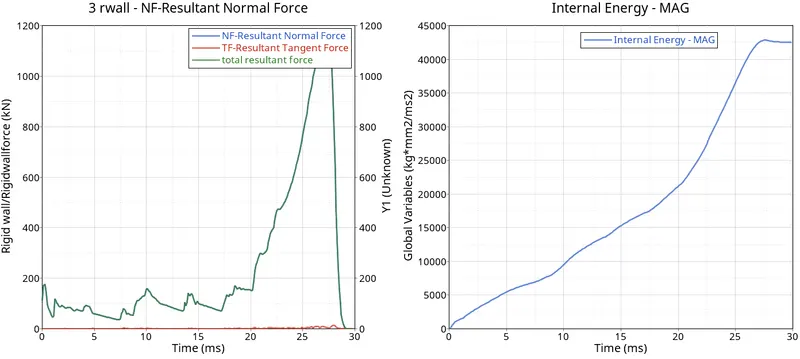
CASE 5: Create a new notch in the middle ,select the whole section and run.
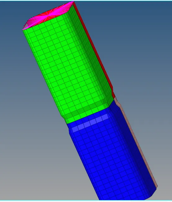
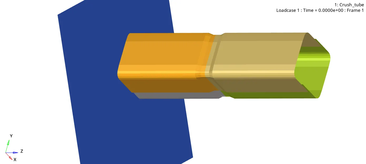
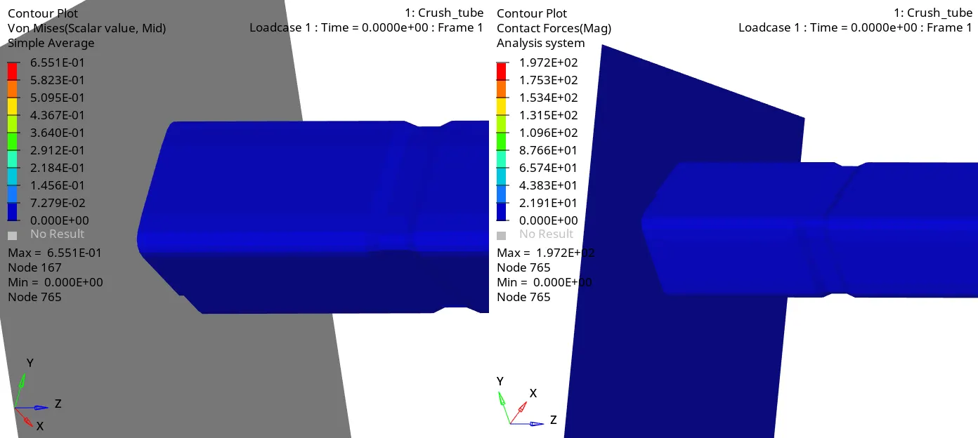
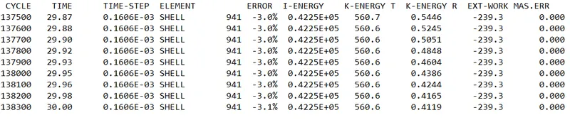
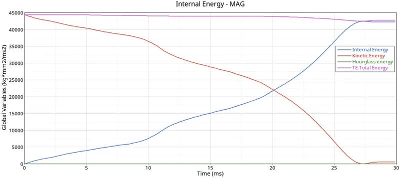
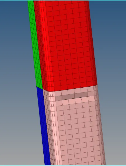
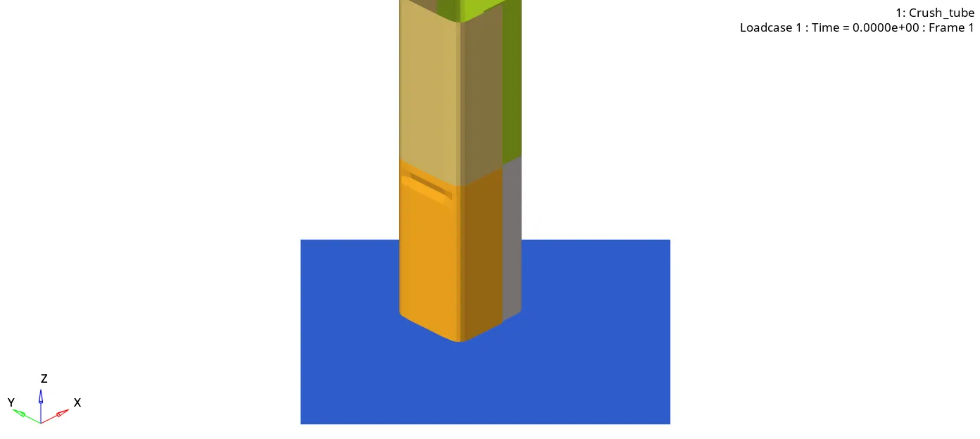
CASE 6: Create a new notch with nodes only from opposing 2 faces and run.
RESULTS AND CONCLUSION:
- By changing the interface parameters and creating new interface card, the results are compared.
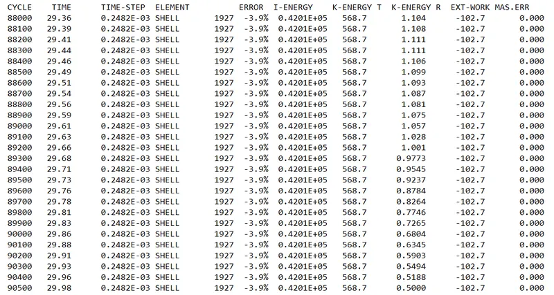
- there is some variation in energy error for each case. The energy error is les in simulation without notch, mass error is zero in all cases.
- If we compare the simulation with notch and without notch, the deformation or buckling starts at the notch area and for without notch case, the deformation or buckling starts at the bottom at point of contact of rigid wall and notch
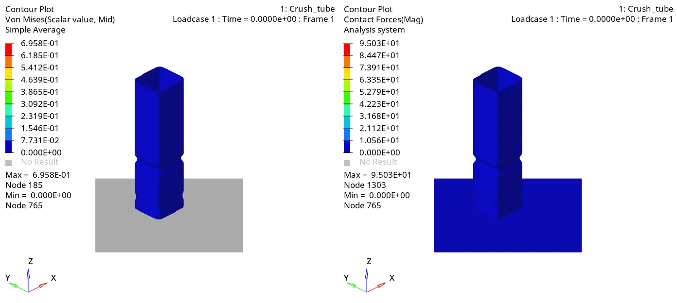
- Due to stress concentration the crush tube get easily defom at the notch area.
- So, we can say that the notch can be used to determine the nature of deformation in crash analysis.
- Contact energy is highest in case 1 and case 2, where type 7 and type 11 interface types are used.