Assignment 5-RADIOSS Interfaces & Study of Effect of Notches Challenge
Objective: To mesh the given bumper model with mesh size of 6 mm. To run the crash tube simulation with given 6 cases and plot the graph for energie,
Procedure to mesh the bumper:
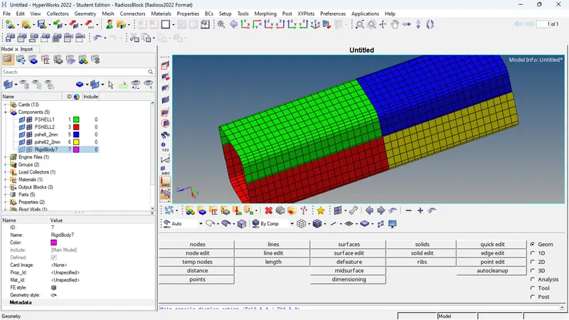
Import the .hm file. Go to File > Import > model. Click on Select File icon. Select the .hm file and click on Import.
Switch to By Topo geometry color mode. Few free edges are found. These are easily fixed by using surface edit tool and edge edit tool available under Geom page.
Go to Preferences > Criteria File Settings > Target element size. Enter Target element size = 6. Now press F12 to go to automesh panel. Enter element size =6 and mesh type to 6.
Perform the meshing manually surface by surface.
Case 1. Run the crash tube model as it is.
- After the Model is imported, The Simulation needs to be performed without changes in model in this case.
- In order to create the THPART we have to click on the output Blocks and create the TH PART , in entity id instead of nodes keep components and select all four components and click on ok. Then the TH part is created.
- To simulate the model, Go to the Analysis tab, Select the Radioss option > Select the location to save the file > Check include collectors box > In the options tab, type “-nt 4” > Click Radioss.
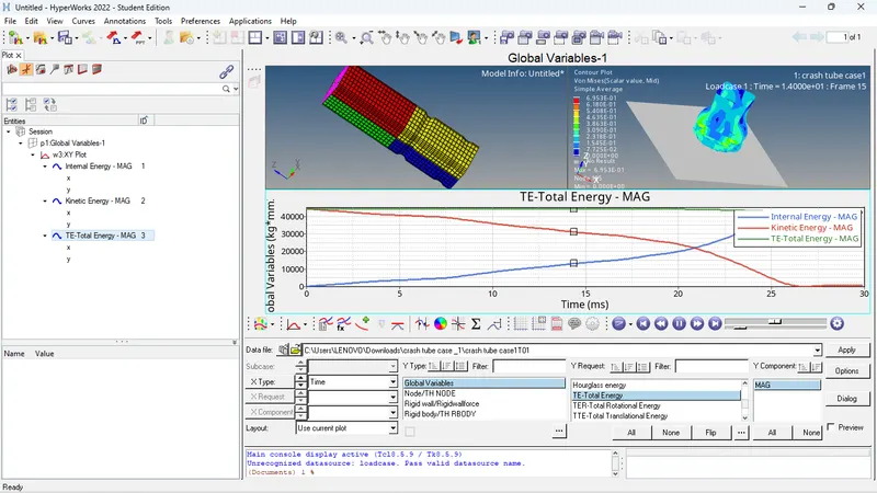
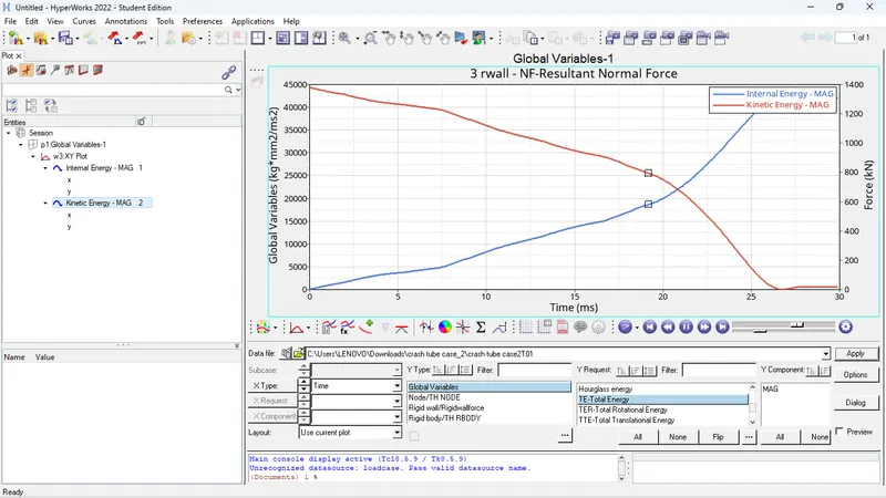
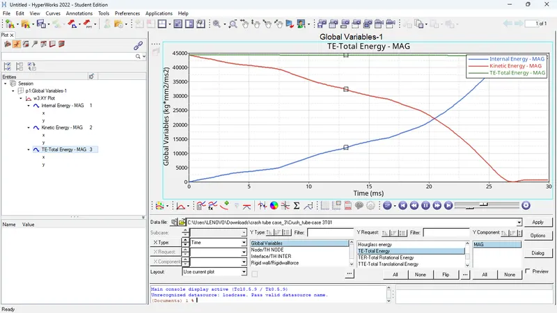
- From output file energy error is -3.8%% and mass error is 0% which is less than -15% to 2% and 1% respectively, so we can accept the results and plot the graphs by using hypergraphs.
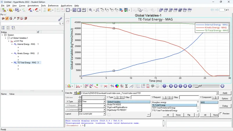
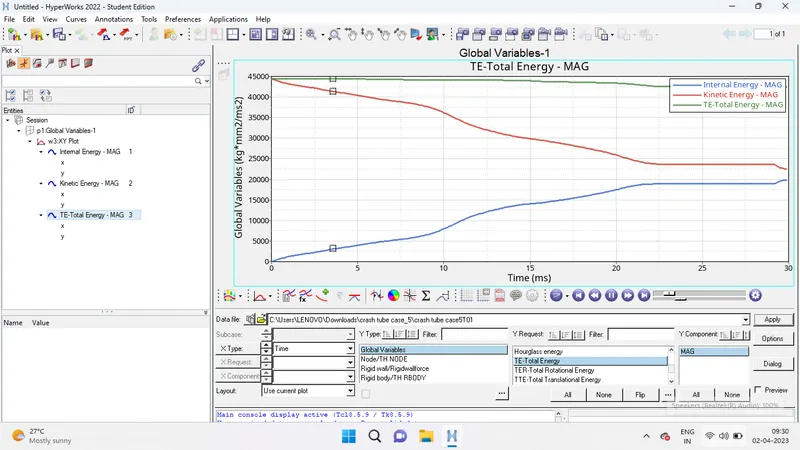
- Open hypergraph 2d for observing the energy plot data from TA01 file
Case 2. Change the Inacti=6 and run.
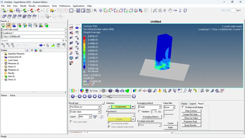
- In this case, the model is imported and run the simulation with recommended properties whereas we have to change Inacti = 6 as per problem statement. The Type 7 contact interface is used with recommended property.
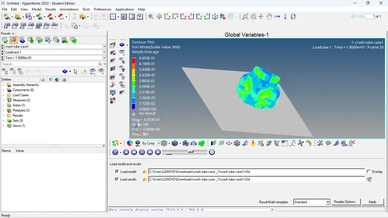
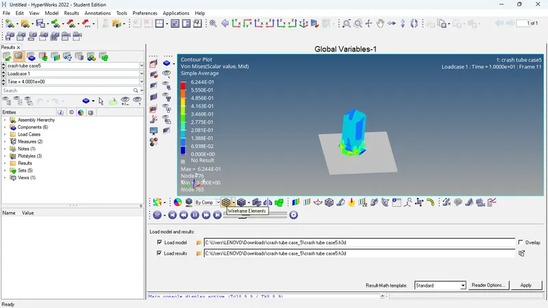
- After changing the parameters run the simulation with same steps to be carried as per previous case. The simulation is shown in GIF below. Plot the graphs of energies same as above case.
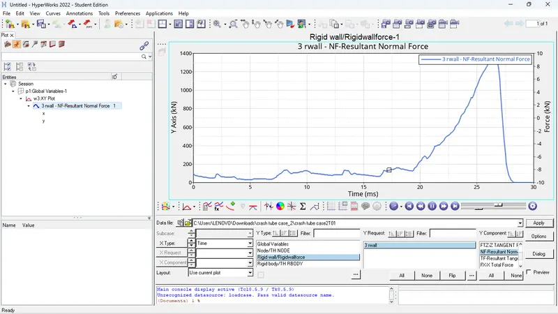
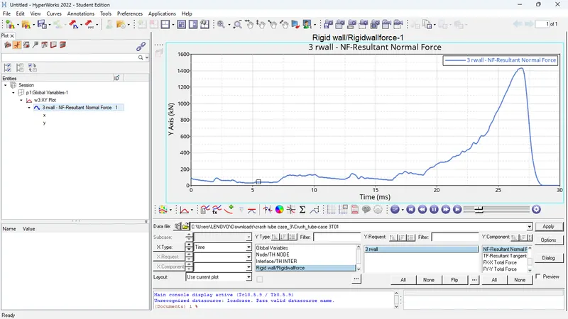
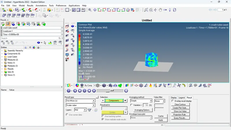
- For this simulation, the max von mises stress is created as 69.53N/mm2 and the max contact force is created as 3 N whereas the time history (TH) for all the components are created in order to study the deformation and energy variation in each component with respect to time.
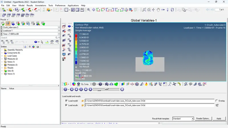
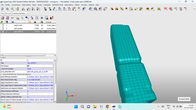
Case 3 :- Create the type 11 contact and run.
- In this case, the model is imported and run the simulation with recommended properties whereas we have to change Card image as Type 11 contact as per problem statement.
- Type 11 takes into the account of the connections made by the edges of the slave segment to the edges to master segment and hence improves the accuracy of the reactive forces calculations.
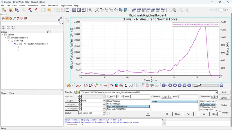
- For this simulation, the max contact force is created as 112.5 N whereas the time history (TH) for all the components are created in order to study the deformation and energy variation in each component with respect to time.
Case 4 :- Remove both notches and remove boundary condition on rigid body node then run.
- In this case, the notch needs to be deleted and make it into a plane mesh.
- To delete the Notch, go to the Tools panel and select Delete option > Select the Elements to delete > Click on delete Entity.
- The Notch elements are deleted.
- To create a plane surface, go to the 2D panel, Select Ruled option > Select the first Node list > Select the Second Node List > Click Create. >> The mesh is created Give the element length as 6 > Click Recalculate > Click mesh.
- The mesh is created properly.
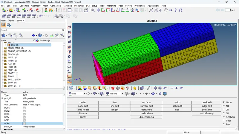
- Now to delete the Boundary conditions, go to the Solver Deck, If the Solver deck is not visible, Go to the View tab in the Standard menu bar > Click Browse > Click Hyper Mesh > Click on Solver > The Solver Deck will be opened. > Delete the BCS Entity in the Solver Deck.
- To simulate the model, go to the Analysis Panel, Select the Radioss Option > Select the area to save the file (Note: Save the File in separate folder naming Case 4 as it will be easy to check the models) > Check include collectors box > In the options tab, type “-nt 4” > Click Radioss. The Simulation is run successfully.
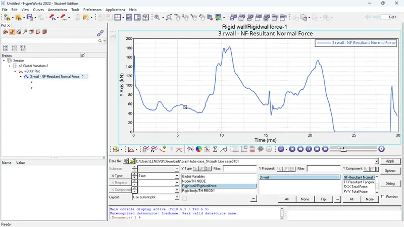
- For this simulation, the max contact force is created as 61.09 N where as the time history (TH) for all the components are created inorder to study the deformation and energy variation in each component wrt to time.
Case 5 :- Create a new notch in the middle ,select the whole section and run.
- In this case, the model is imported and run the simulation with recommended properties where there is Notch presented on the middle surface and also the boundary conditions are removed. The Notch is created with the magnitude or depth of 3mm. The Type 11 contact interface is used with recommended property.
- To simulate the model, go to the Analysis Panel, Select the Radioss Option > Select the area to save the file (Note: Save the File in separate folder naming Case 5 as it will be easy to check the models) > Check include collectors box > In the options tab, type “-nt 4” > Click Radioss. The Simulation is run successfully.
- For this simulation, the max contact force is created as 61.94 N where as the time history (TH) for all the components are created in order to study the deformation and energy variation in each component with respect to time.
Case 6 :- Create a new notch with nodes only from opposing 2 faces and run.
- In this case, a notch should be created at the same place in the opposite direction.
- Again, to create a notch, the Translate option is used.
- Go to the Tools panel, Select Translate option > Select the Nodes to translate > Select the Orientation of the elements (i.e., in which direction the elements should be moved) > Give the Magnitude as 2 (Distance from node to node).
- The Notch is created.
- To simulate the model, go to the Analysis Panel, Select the Radioss Option > Select the area to save the file (Note: Save the File in separate folder naming Case 6 as it will be easy to check the models) > Check includes collectors box > In the options tab, type “-nt 4” > Click Radioss. The Simulation is run successfully.
- For this simulation, the max contact force is created as 69.45 N whereas the time history (TH) for all the components is created in order to study the deformation and energy variation in each component with respect to time.
Conclusion :-
- The Bumper model have been meshed and welded (seam) with the element size of 6mm and ready for further solving and post-processing.
- All the 6 cases of crash tube have been simulated and results are compared using various energies plot.