Assignment 5-RADIOSS Interfaces & Study of Effect of Notches Challenge
Aim: Mesh the given compmonent & Run the crash box simulation to study the interface & notches effects.
Procedure :
Case : Create the mesh for bumper assembly,mesh size should be 6mm.
Procedure :
Import the geometry in hypermesh> Radioss solver
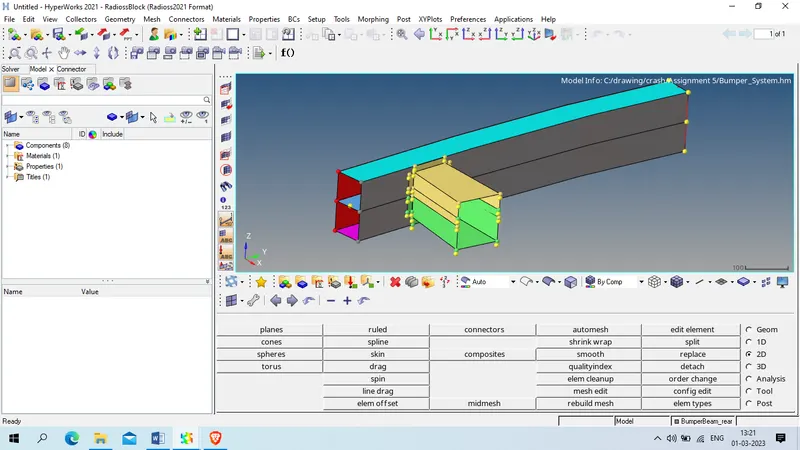
Now , check the component , asthe given geometry is only extracted mid surface with predefined material and property as given below
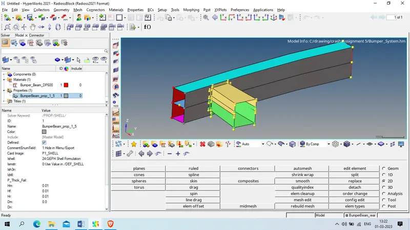
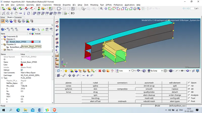
Now we check any error in between surface ,
as we check we found their is connectivity issue on below region , we will clear that using surface edit and
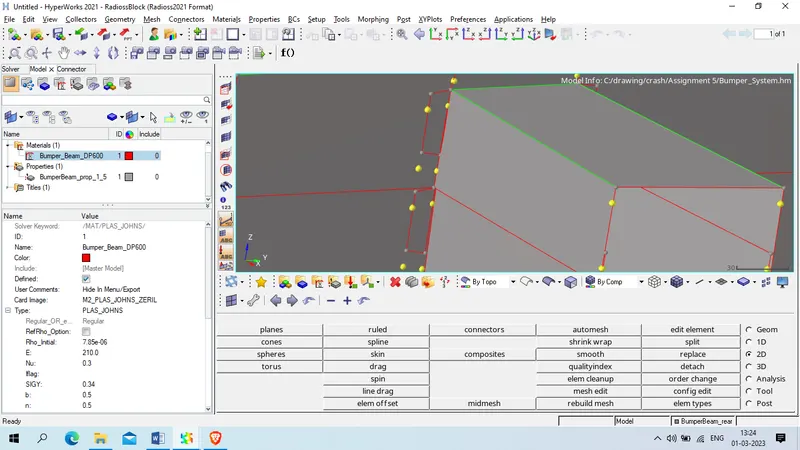
now we use surface to surface edit trip option and allow to trim both body
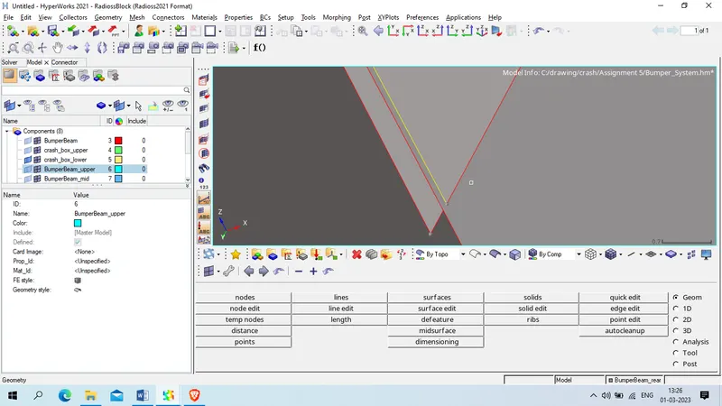
Now we delete extra portion
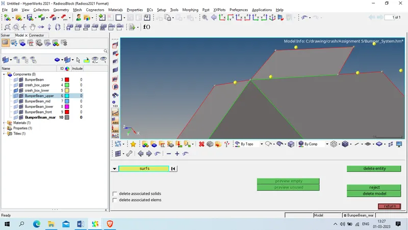
repeat the same for other side and proceed for mesh
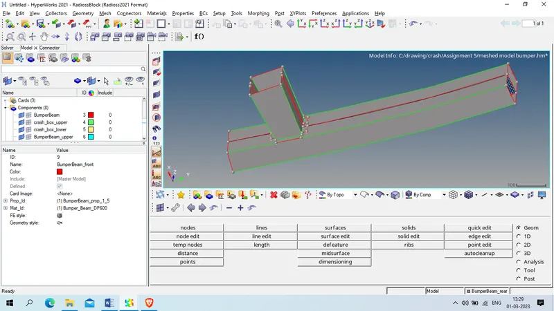
for meshing we go to 2D> automesh and select the surface
Element type : mixed , Element size : 6
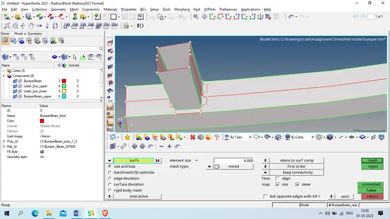
Click on mesh , and adjust the nodeon every edge to get proper mesh element
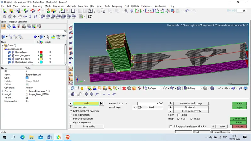
After mesh , we will deploy connection between Crash_box and bumper_beam
for that we will go to 2D> connector > spot
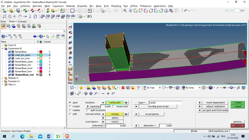
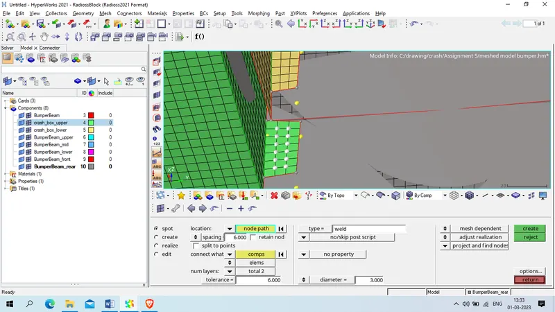
Select the node path as shown below
Type as : weld/sprig/rigid any type as we required
Spacing : 6
tolerance : 6
Diameter : 3
rest setting as it is
Click respective component as shown below
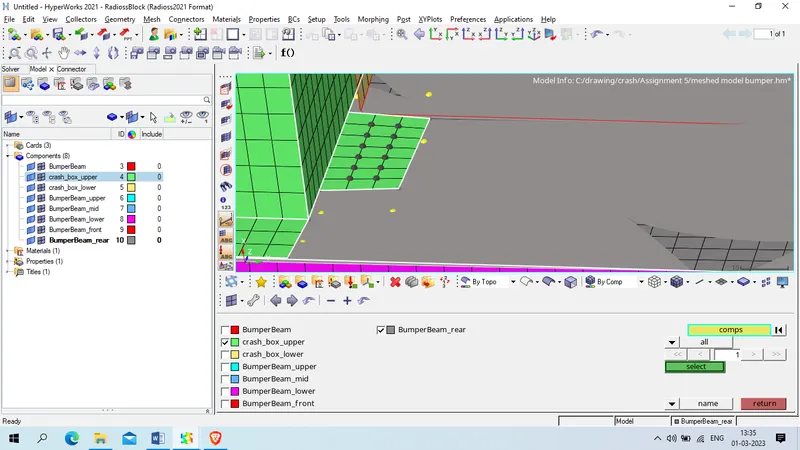
NOw click on create
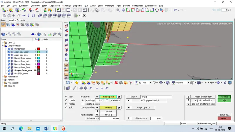
checked as our connection is realized we move further for next connection and repeat the connection all side .
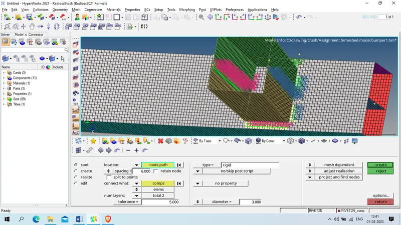
Now save the model .
Crash_Box Simulation study :
Case 1: Run the crash tube model as it is.
Procedure: Open the 0000.rad file in hypermesh> Radioss solver
Check the material component
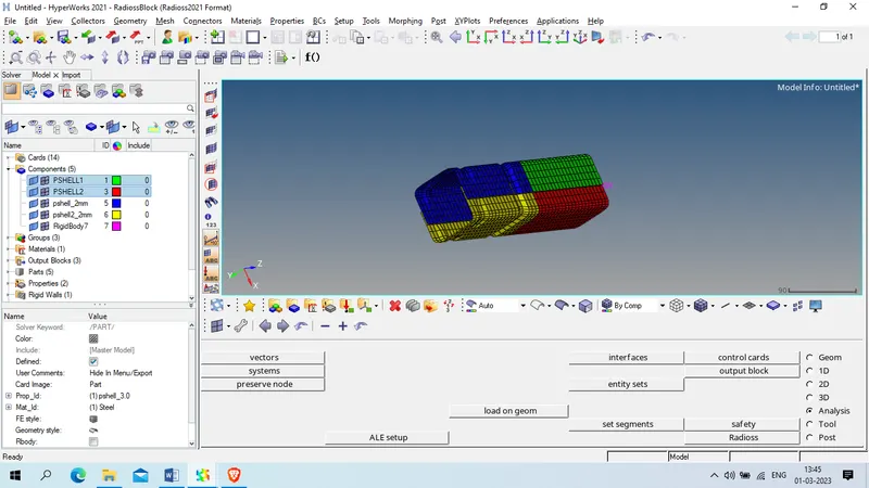
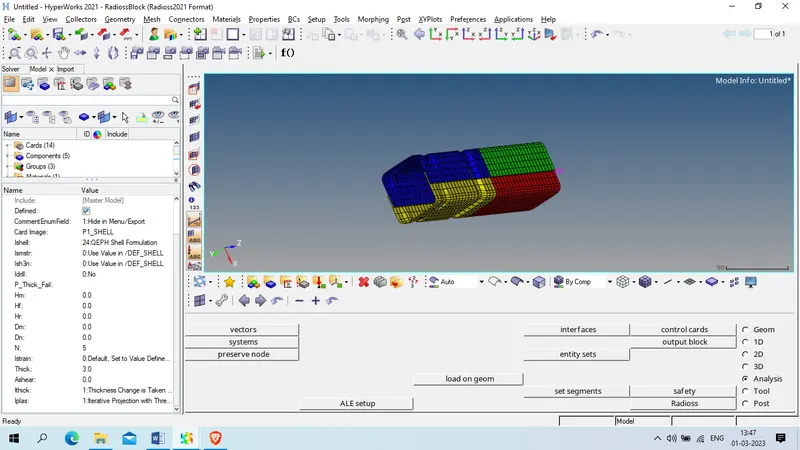
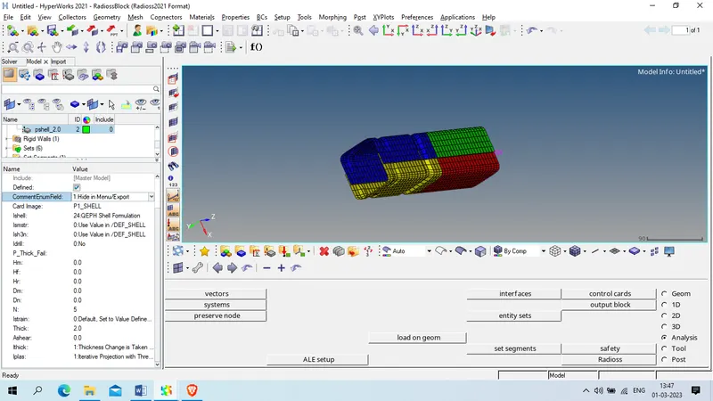
these two component are assign with 3 mm and rest two are assign with 2 mm property.
3 mm property as given below
Ishell : 24
Ismstr:0
Ish3n: 0
N:5
Thick: 3
Ithick: 1
Iplas :1
2 mm property as given below
Ishell : 24
Ismstr:0
Ish3n: 0
N:5
Thick: 2
Ithick: 1
Iplas :1
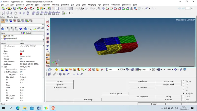
Material used for component is steel with Material card as 2: Plas_johnson_Zeril
The properties of material given below
Type : Plas John
Rho : 7.85E-6
E: 210 GPa
Nu : 0.3
SIGY: 0.206
b: 0.45
n: 0.5
Ismooth : 0
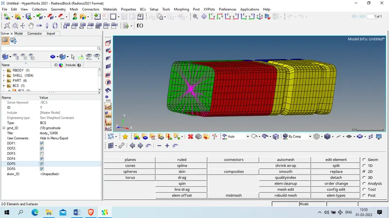
Boundary consition as given below
it have contrain in X and y direction traslation and all direction rolation .
it allowd only in z axis movement
Intial velocity :
it was defined in negative Z AXIS with magntude of 13.3 mm/ms
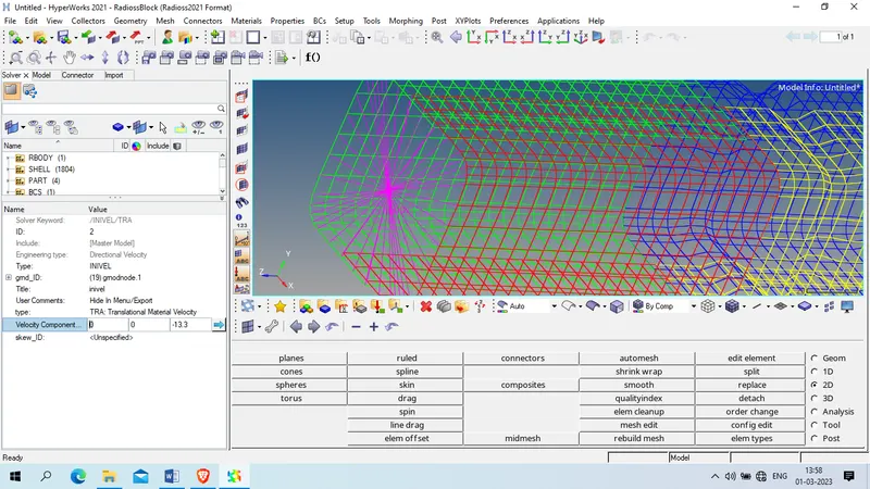
Interface type: we have two interface one is type 2 which is used on weld properties and other is type 7 which is node to surface contact
details as given below
Type 2 Interface
Spotflag: 0
Ignore: 0
Idel2: 0
Dsearch :5
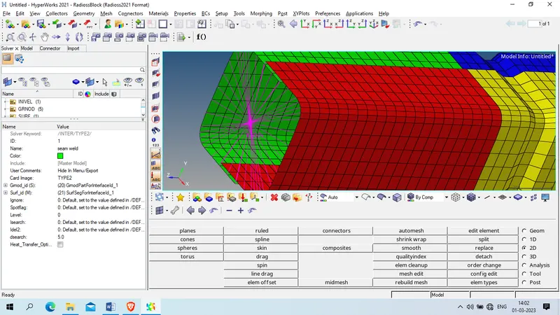
Type 7 Interface
Istf: 4
Igap: 0
Idel:0
Stmin:1
Fric:0.2
Gapmin:1
Inacti:0
Iform: 2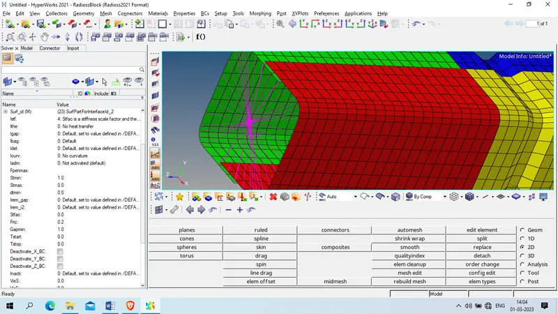
Rigid wall was placed at one end as shown below
Dsearch :100
Fric:0.2
ifq:0
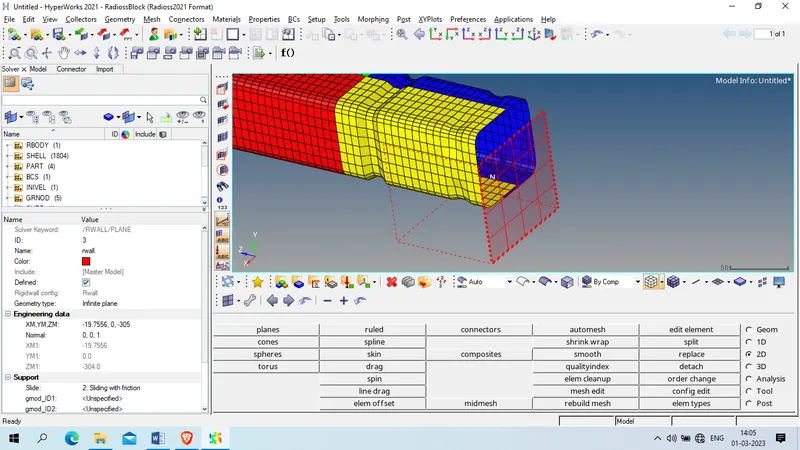
AMIN card is define as below
Tstart: 0
Tfreq:1
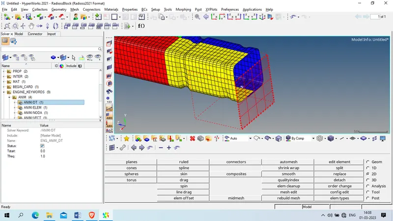
ANIM Print
N_print : -100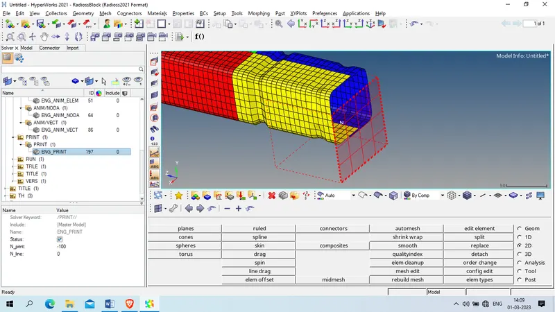
Tstop : 30s
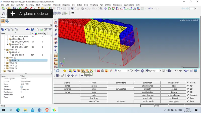
one end is deloyed with Rigit body as shown below
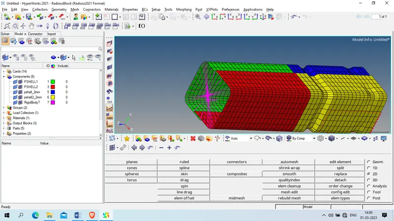
Now we check all required parameter we will run with same paramete
for that goto analysis > radioss > set path
Export option : all
option :-nt 4
click on run
Case 2: Change the Inacti=6 and run.
for this we will go to Type 7 interface and change the Inacti to 6 which is previouly set at 0
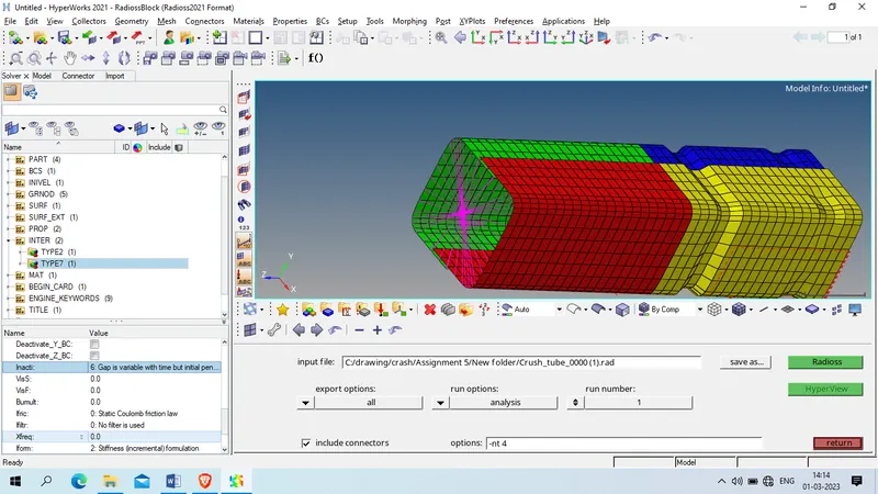
all the rest setting will be as it is and we will run this case also in analysis > radioss> set path ( in different folder with different name
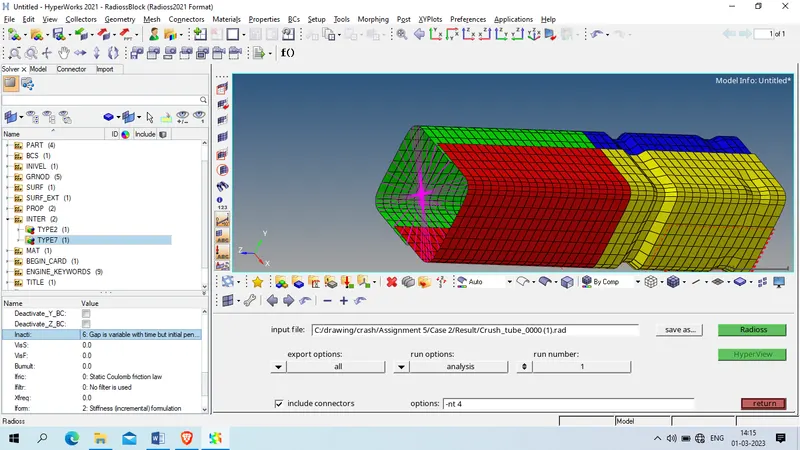
click on radioss to run the simulation
Case 3: Create the type 11 contact and run.
for this we will impement type 11 inteface with below criteria
Istf:4
Igap:1000
Stmin: 1
Fric:0.25
Gapmin:0.45
Inacti:6
select slave node : 2 body and Master rest 2 body
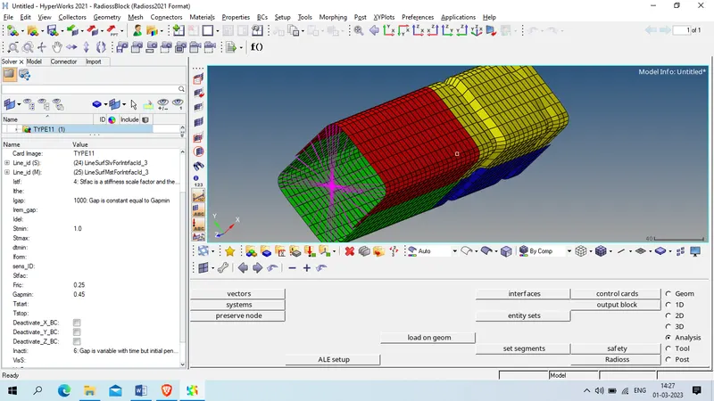
rest other setting will be remain as it s
for run this case we will export this model in different location and go to analysis > Radioss > set the path for case 3 > export option : all> Option: -nt 4
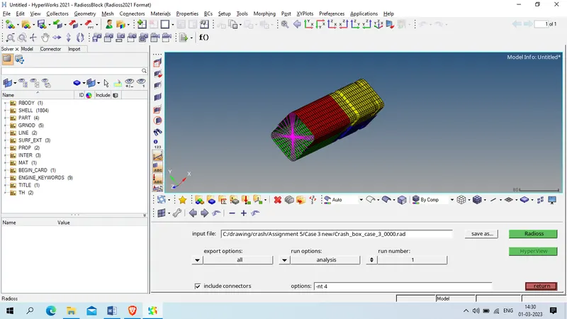
Click on radioss to run the simulation.
Case 4: Remove both notches and remove boundary condition on rigid body node then run.
Procedure :
for this we will go to Geom> node edit > allign node
Select the node as given below
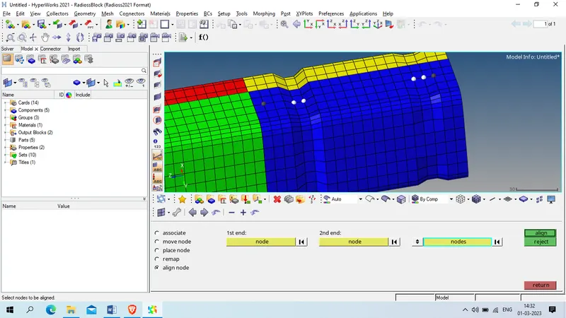
click on align
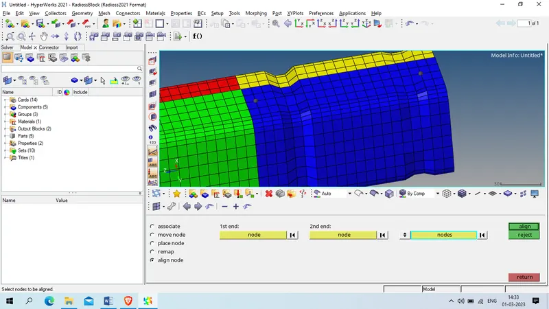
Repeat the same process for all node till the notch get remove .
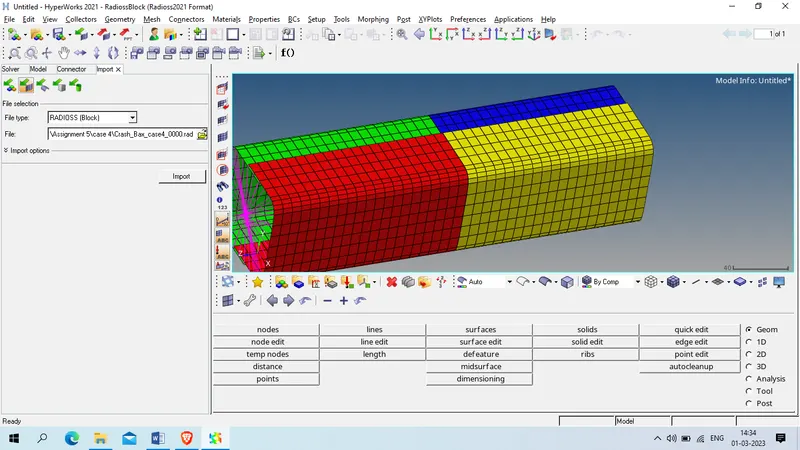
Now run this case, for that export this model in seperate location and go to analysis > radioss > set the path> Export option : all > option :-nt 4
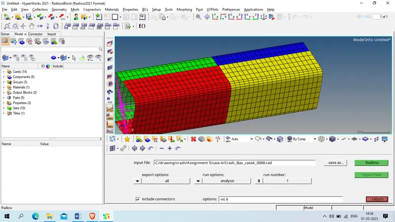
CLick on radioss to run the simulation
Case 5: Create a new notch in the middle ,select the whole section and run.
procedure :
for this we will go to tool> Translate > select the node as shown below
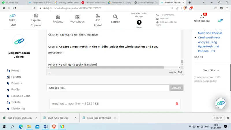
Select direction N1 and N2 and click on trasnlate whith magnitude of 1 in 4 step
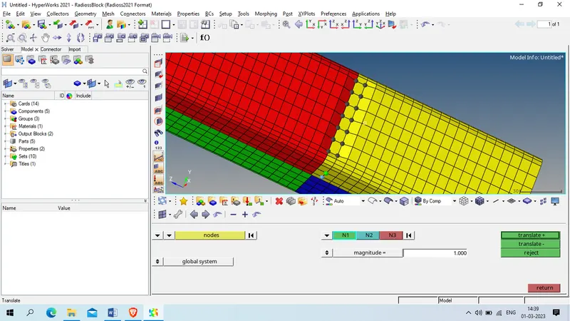
again do the same for other side as shown below
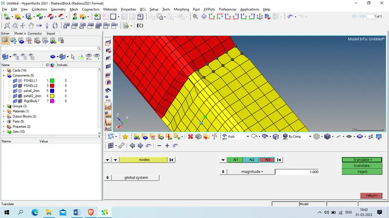
now align rest node with the help of Geom> node edit > Align node
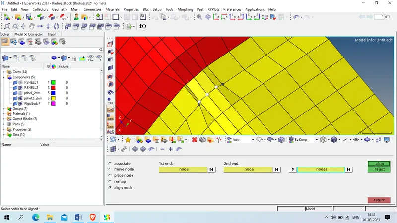
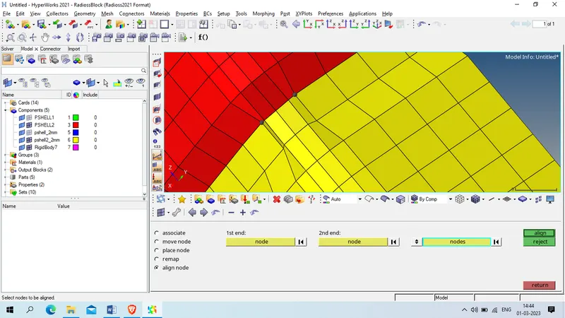
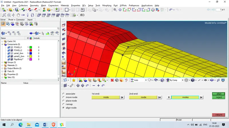
Now repeat same for for all region to get proper notch
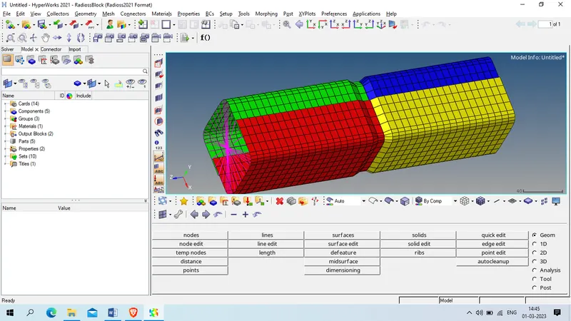
NOw we will run this case
go to Analysis > Radioss > Select the path > Export option : all > option : -nt 4
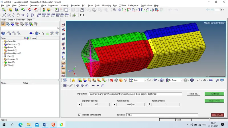
CLick on radioss to run the simulation
Case 6 : Create a new notch with nodes only from opposing 2 faces and run.
We will no notch with same process in case 5 , we select the region as below
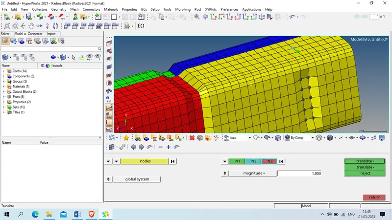
repeate the same process for opposite face
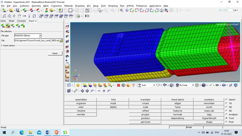
Now run the simulation using Analysis > Radioss > Select the path > Export option : all > option : -nt 4.
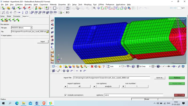
Click on radioss to run the simulation
Result :
Case 1:
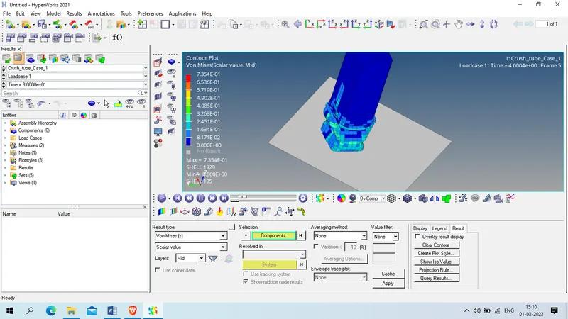
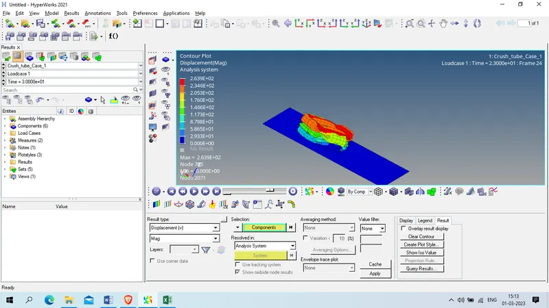
Displacement :
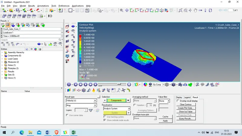
Velocity :
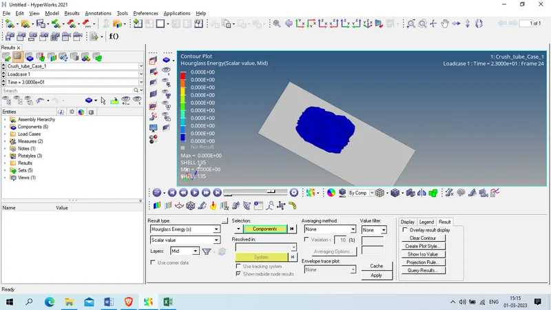
Hourglass energy
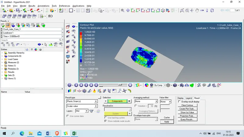
Plastic strain
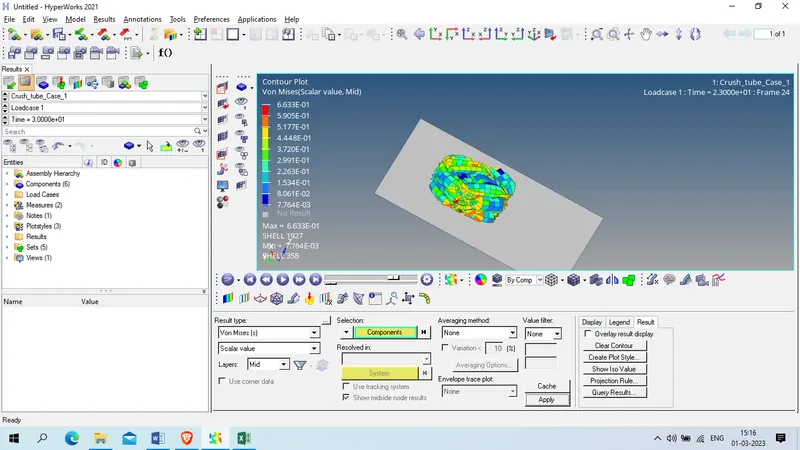
Von Mises:
Plots
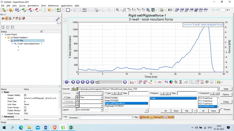
Total resultant force
Conclusion :
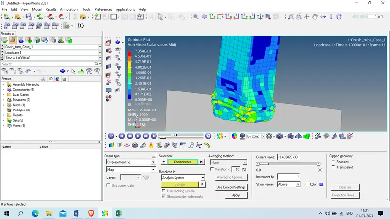
we had observed that having a notch between the flat surface , notch area will deform first after application of load, after that rest area will deform respectively .
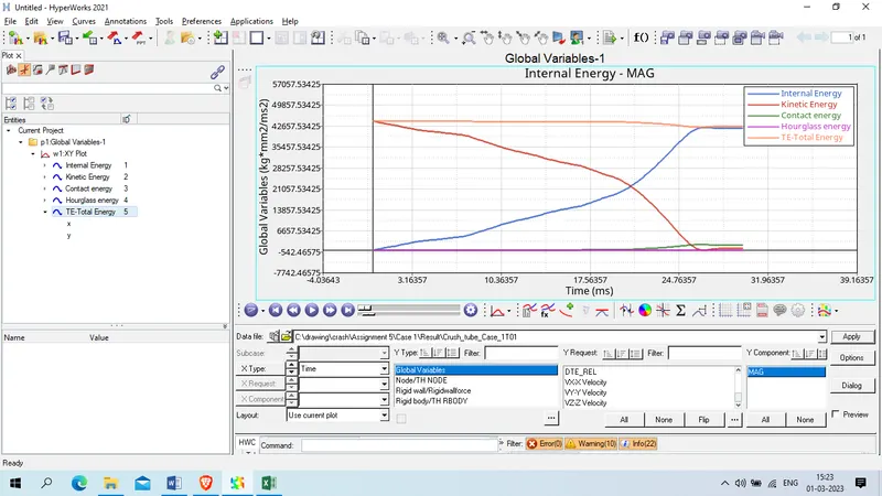
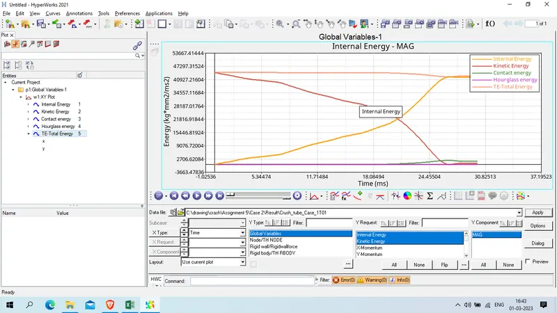
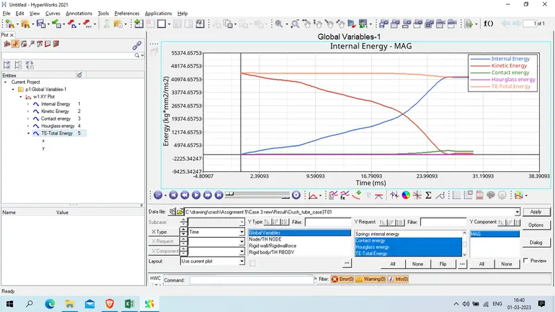
The kinetic energy is maximum at the beginning which starts decreasing once the crush tube impacts the rigid wall. This energy is converted into strain energy as the crush tube deforms.
Energy error is about -3.8% which is acceptable. and mass error is zero.
from graph we observed that as the total energy reduced the contact energy increase.
Case 2:
Displacement
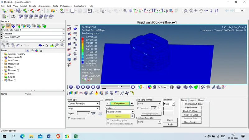
Contact force:
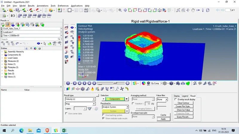
Velocity
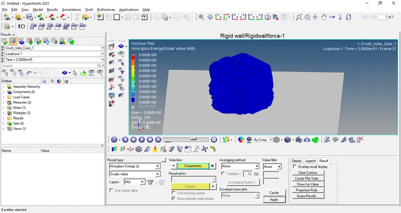
Hourglass Energy
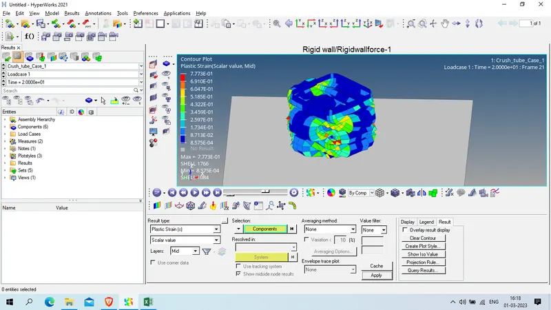
Plastic strain
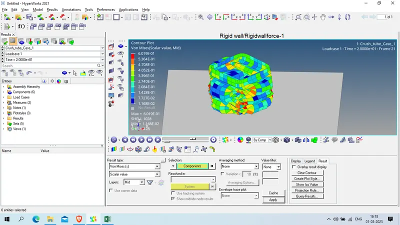
VOn Mises Stress
Plot
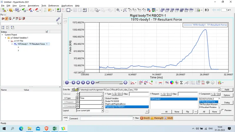
Total force reaction at rigid wall
Conclusion:
we induces interface Inacti as 6, thus the gap between slave node and master surface is reduced so that the acuracy is increase. thus ot remove all intial penetration at begning .
in this case also we had seen the notched area are deform first then rest body.
The energy error is same as in case 1. which is -3.8% . this are acceptale. mass error is zero.
Case 3:
Displacement
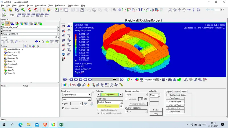
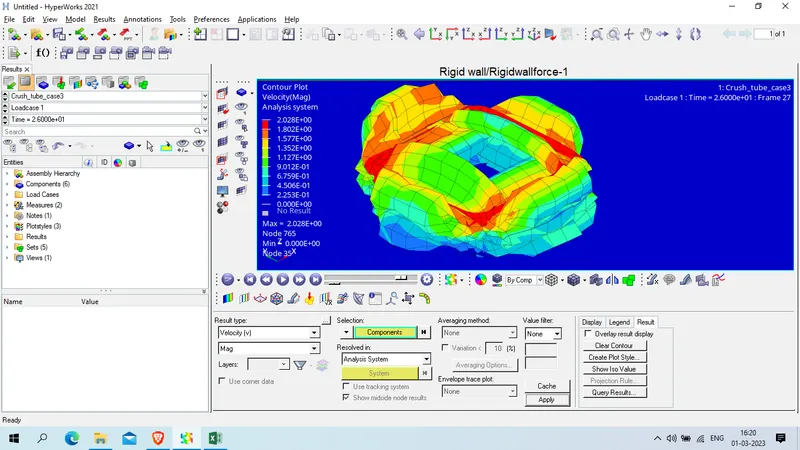
Velocity
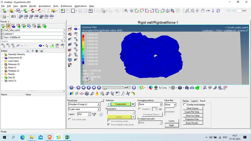
Hourglass Energy
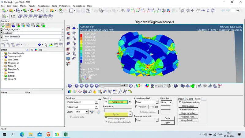
Plastic Strain
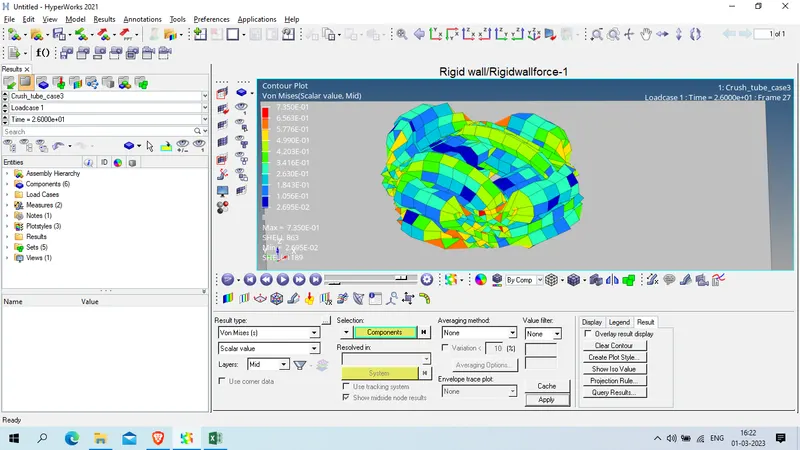
Von mises stress
Plot
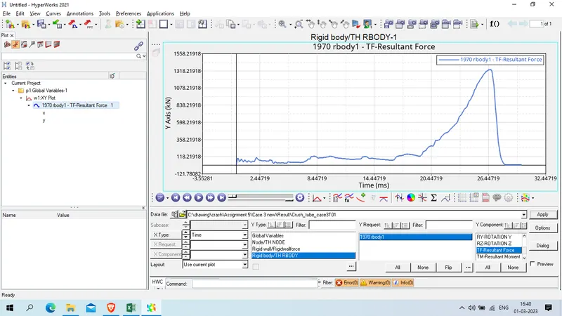
Total force reaction at rigid wall
COnclusion :
We used type 11 interface so that the edge to edge penetration is prevented . the nature of deformation and energy graph nature are similiar as previous case. The notched portion is first to deform. Energy error is about -3.8% which is acceptable.
Case4:
Displacement
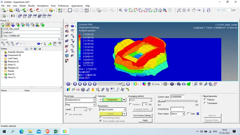
Velocity
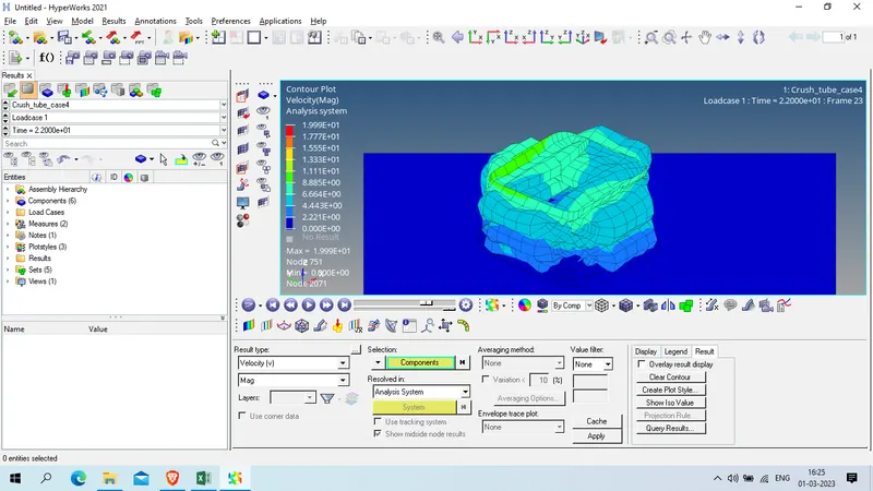
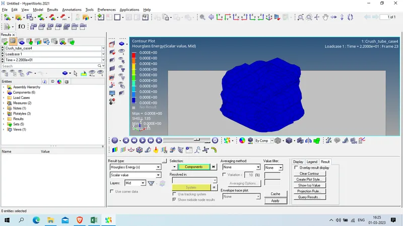
Hourglass ENergy
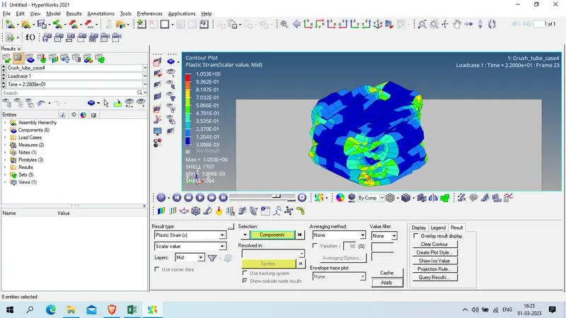
Plastic strain
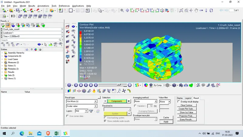
VOn mises STress
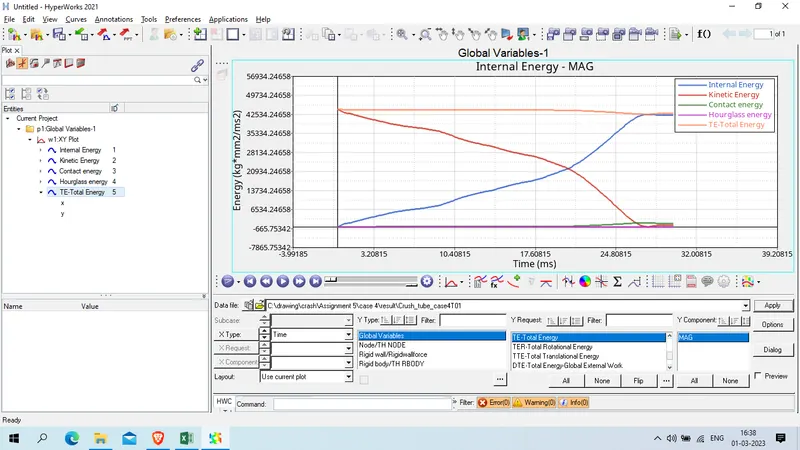
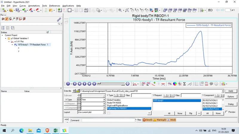
Plot :
Total force Reaction at rigid wall
Conclusion
In this case we had removed the notches and DOF. During impact, there is no localized deformation as there are no notches present and the deformation progresses as expected. The nature of energy graph is also similiar to previous case. Energy error is about -3.0% which is acceptable.
Case 5:
Displacement
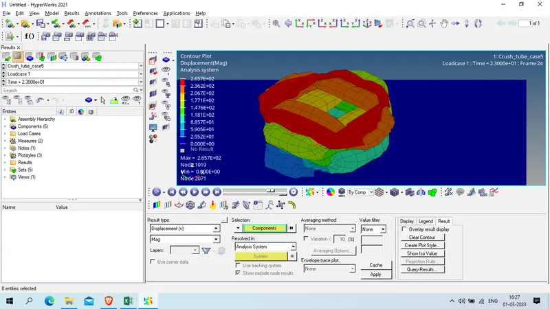
Velocity
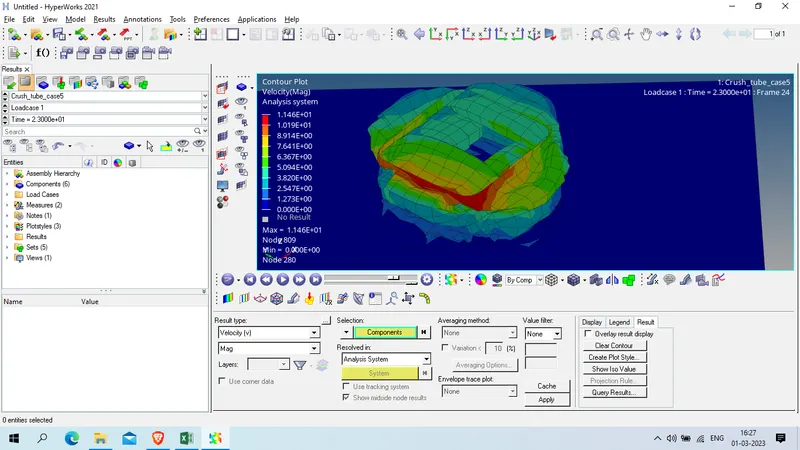
Hourglass energy
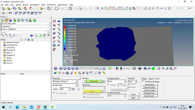
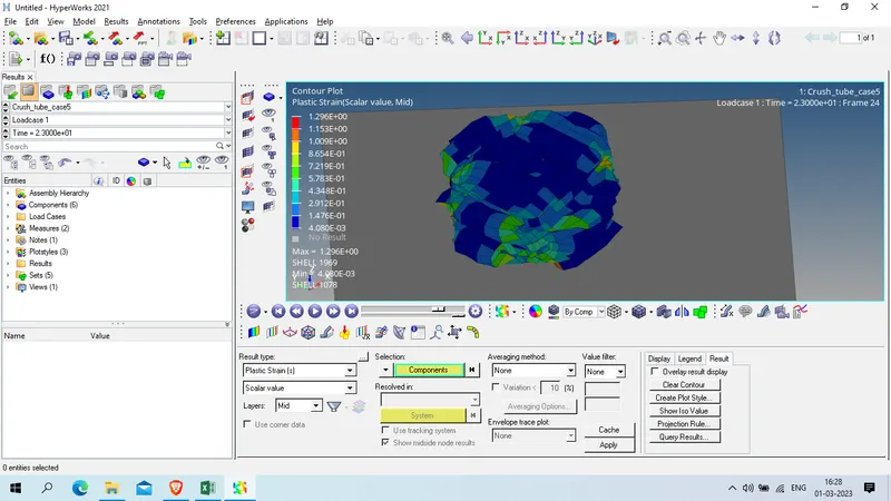
Plastic strain
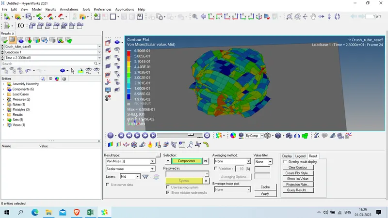
Von mises
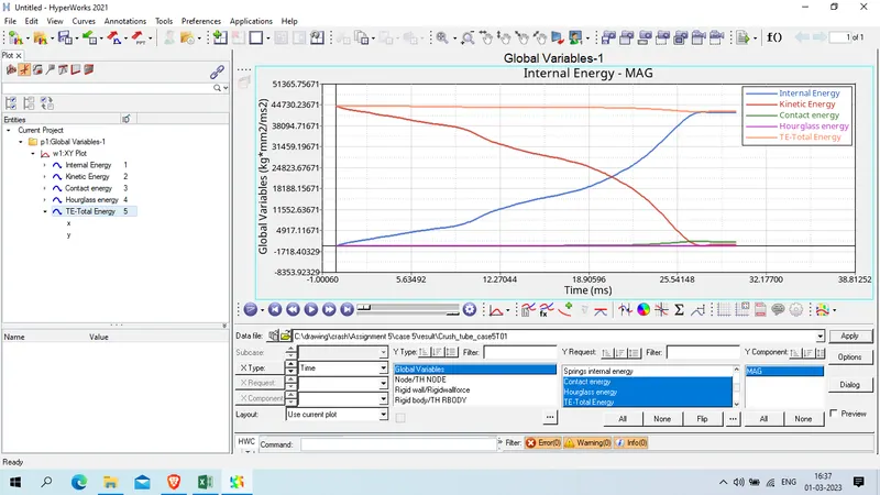
Plot
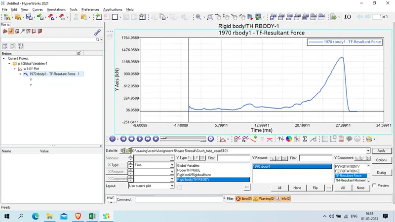
Total force reaction at rigid wall
COonclusion :
We make a notch in mid of the geometry so that .the body which is in contact with rigid wall will deform 1st then the rest body will deform
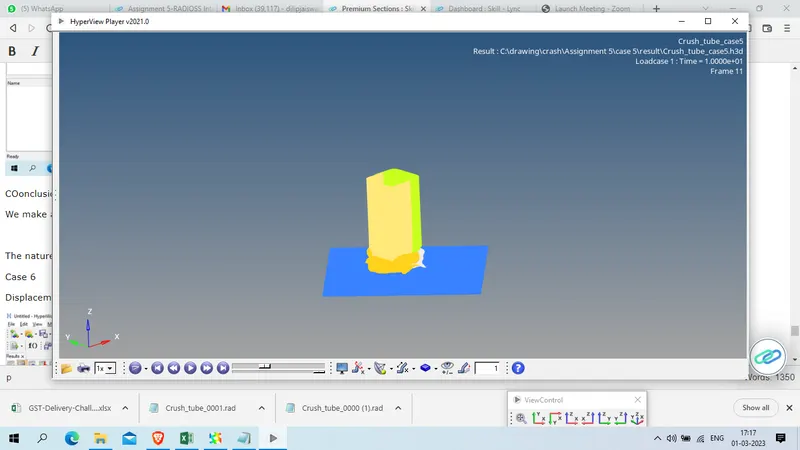
The nature of deformation and the energy graph are similiar in nature compared to previous cases. Energy error is about -2.9% which is acceptable.
Case 6
Displacement
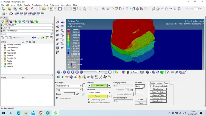
Velocity
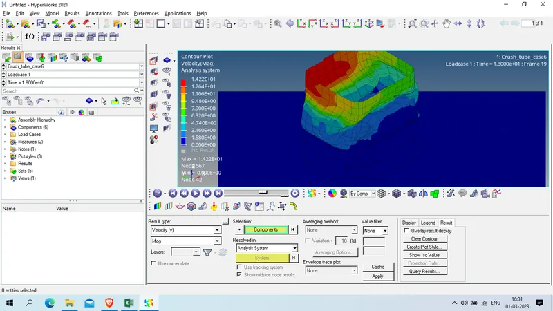
Hourglass energy
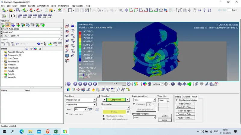
Plastic strain
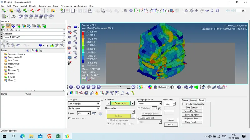
Von mises
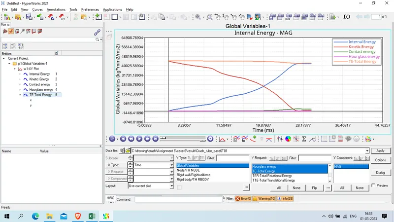
Plot
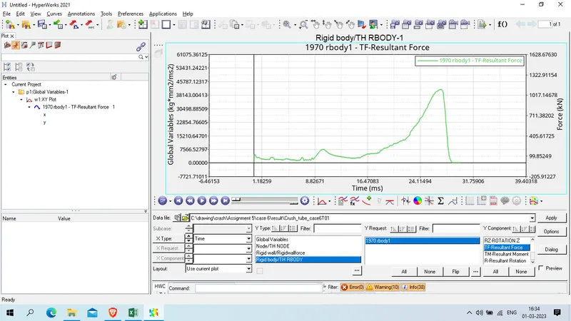
Total Resultant force at rigid wall
Conclusion :
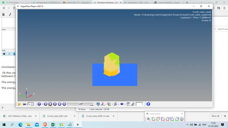
IN this case we had given two extra notch , the deformation 1st as previosus case like it deform 1st which body direct in contact with rigid wall first then the body bettween both notch will deform and at last end piece of the ccrash box will deform .
The energy error in this cases -4.2% which is also acceptable .
The energy graph behavior is same as in previous cases.