Assignment 5-RADIOSS Interfaces & Study of Effect of Notches Challenge
Aim - To mesh the bumper model with a 6mm element size & run the crash tube simulation with different cases given.
Procedure -
Import the bumper model as shown:
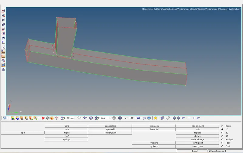
Mesh the given model with a 6mm mesh size as shown:
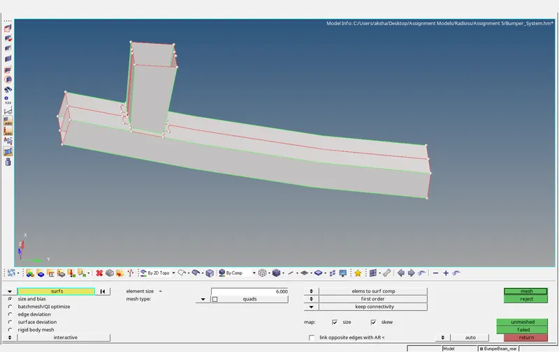
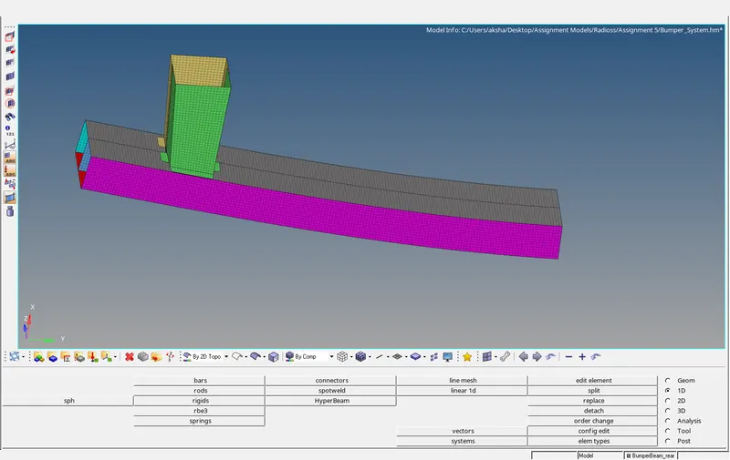
The Meshed model is as shown:
Now we create 1D connectors - Seam welds to join the bumper model as shown :
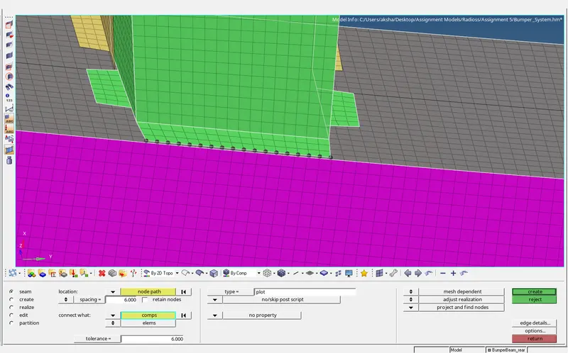
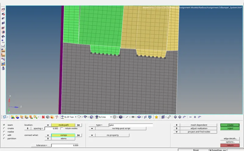
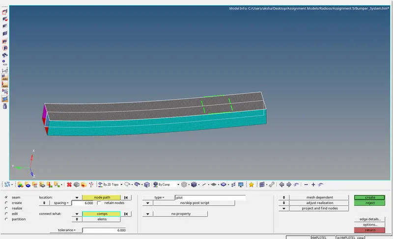
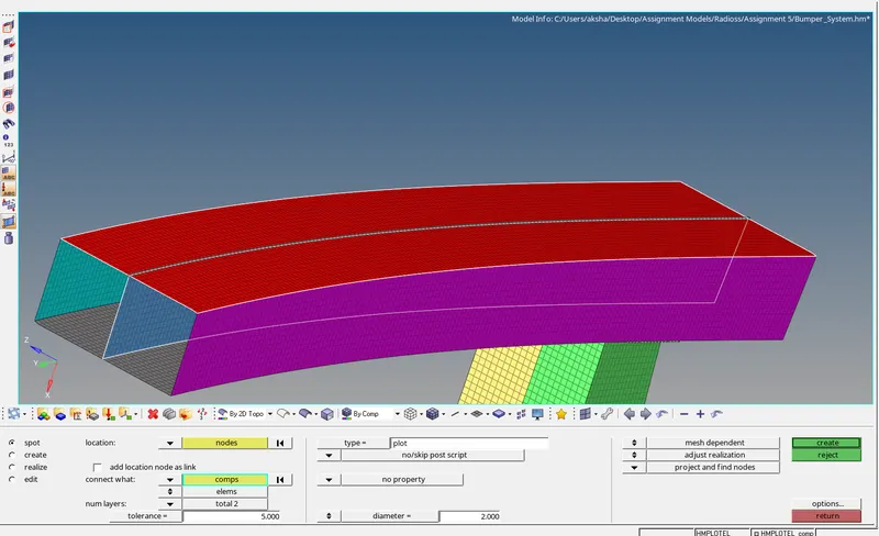
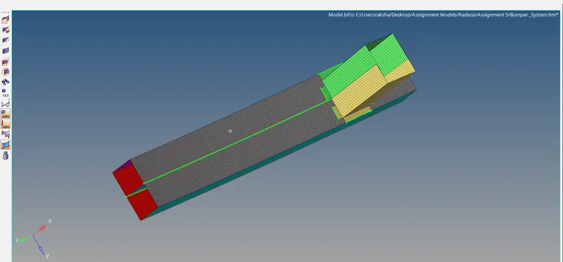
All the connections have been realized as shown below:
Case 1 - Running the Crash tube Model as it is:
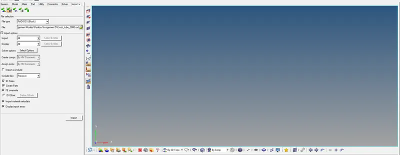
Import the solver deck as shown :
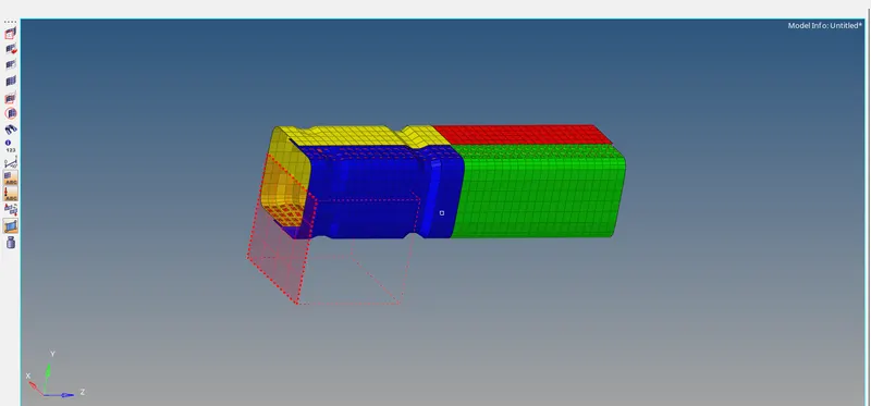
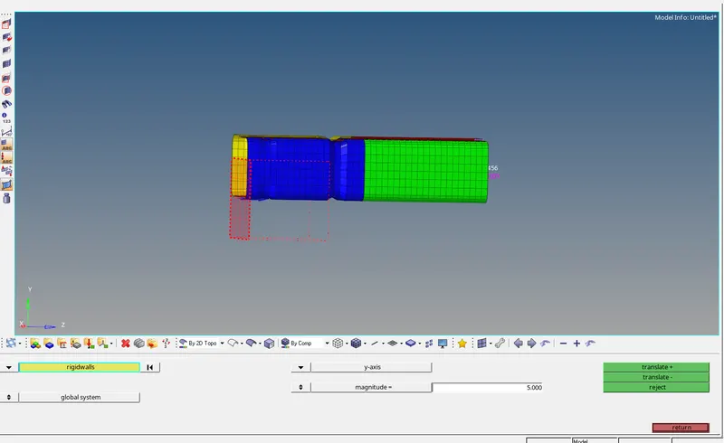
Adjust the Rigid wall position for proper impact as shown:
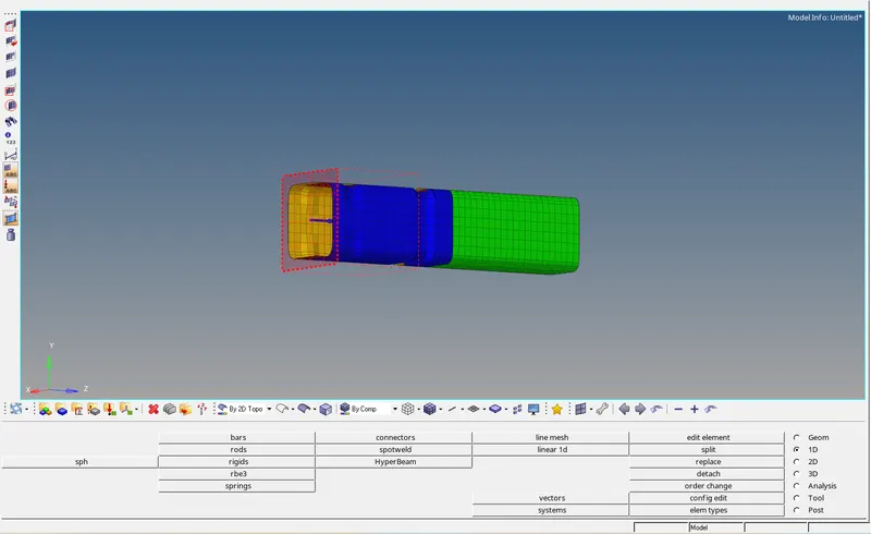
Now we run the analysis as it is:
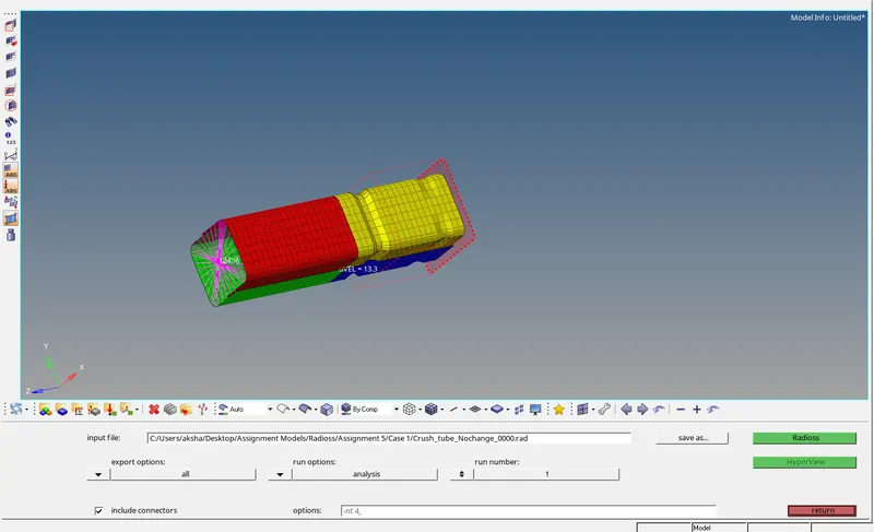
We check for the Energy & Mass Errors as shown:
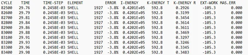
The energy error is -3.8% & the mass error is 0 which is in an acceptable range.
Next, we switch to hyper view & hypergraph to run the simulation, view contour plot & Energy Graphs Respectively:
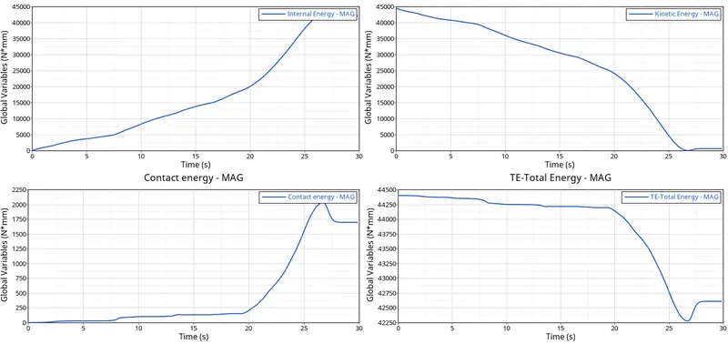
The energy plots are shown below:
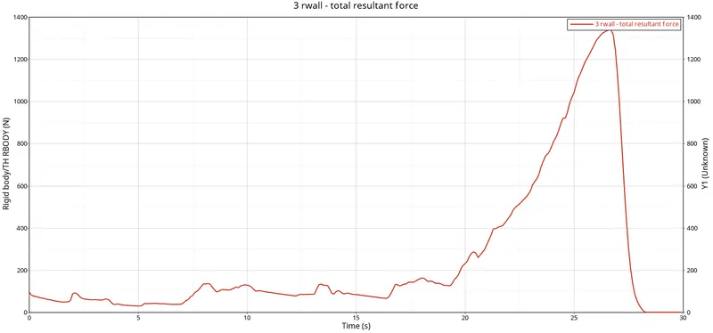
The rigid wall forces are as shown below:
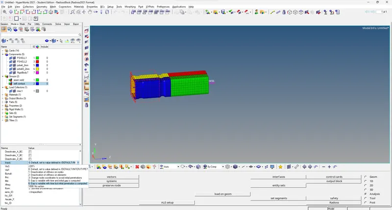
Case 2 - Change the Inacti=6
Change the Inacti =6 as shown below:
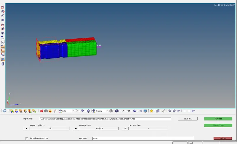
Run the analysis with 4 cores and connectors as shown below:
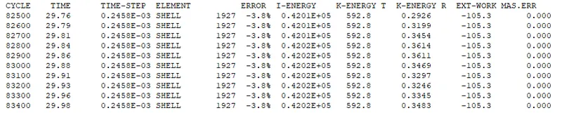
The energy error is -3.8% & the mass error is 0 which is in an acceptable range.
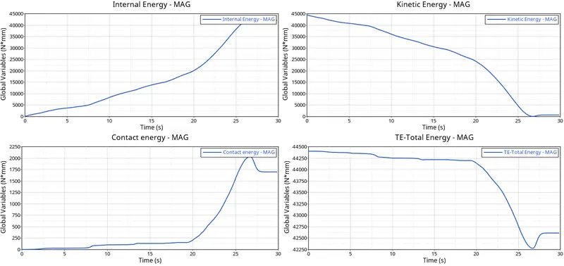
Next, we switch to hyper view & hypergraph to run the simulation, view contour plot & Energy Graphs Respectively:
The Rigid Wall Forces are as shown below:
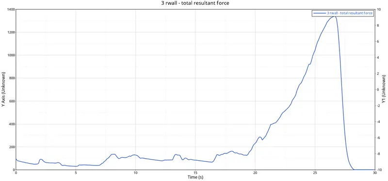
Case 3: Creating type 11 contact
Create the type 11 Contact card with the recommended properties as shown below:
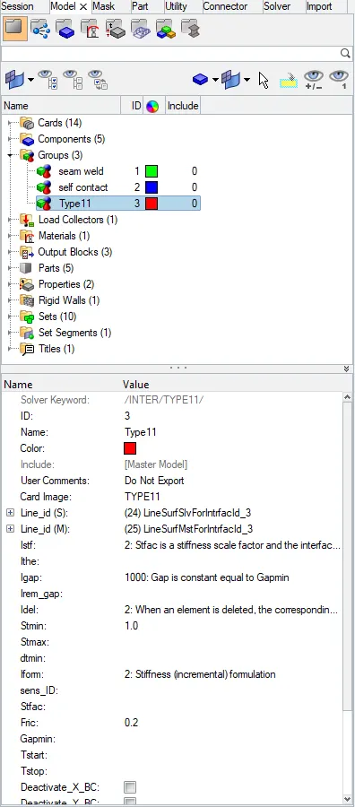
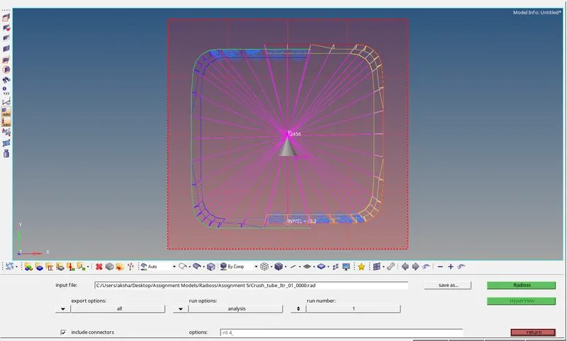

The energy error is -3.8% & the mass error is 0 which is in an acceptable range.
Next, we switch to hyper view & hypergraph to run the simulation, view contour plot & Energy Graphs Respectively:
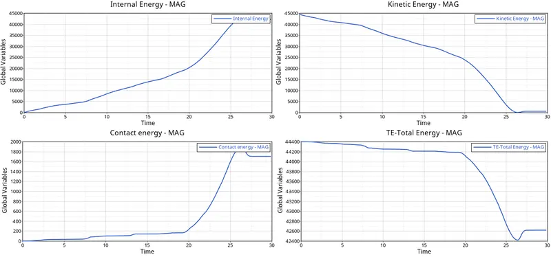
The rigid wall forces are as shown below:
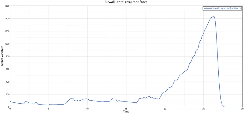
Case 4: Remove Both the notches and Boundary conditions on the nodes-
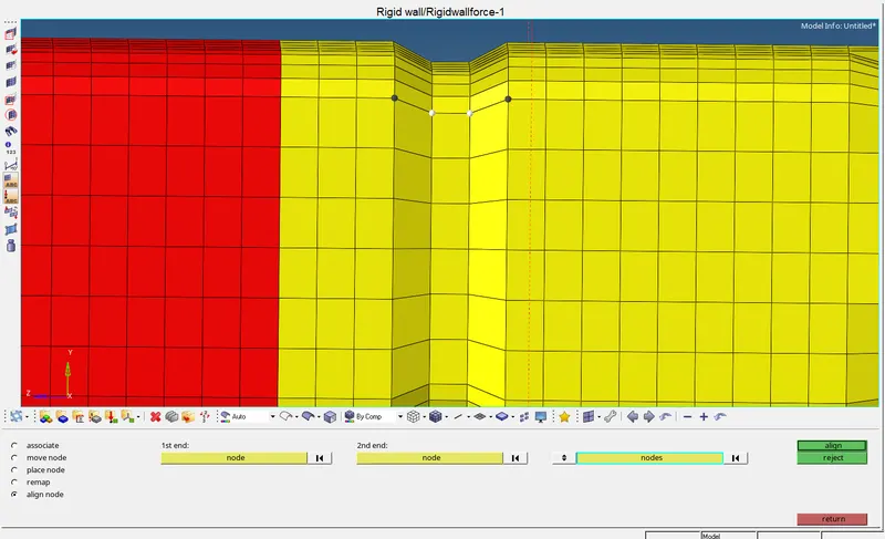
The notches are removed by the align panel, go to F7 - Align- select nodes and align the nodes as shown below:
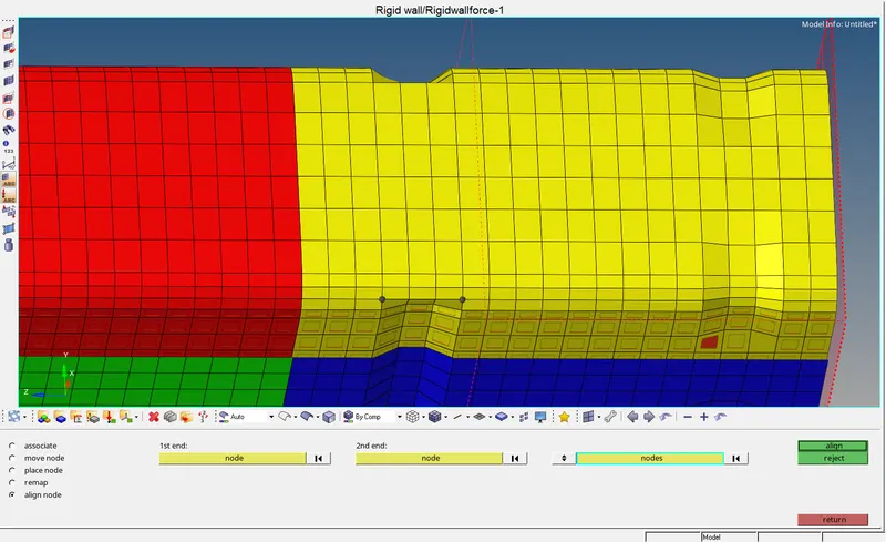
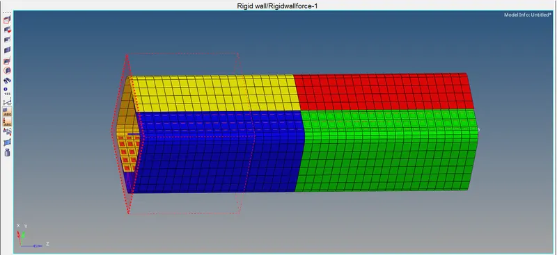
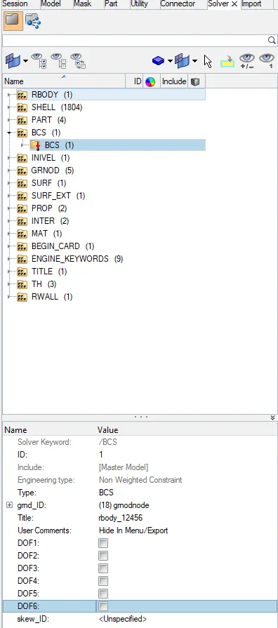
Remove the BCS as shown below:
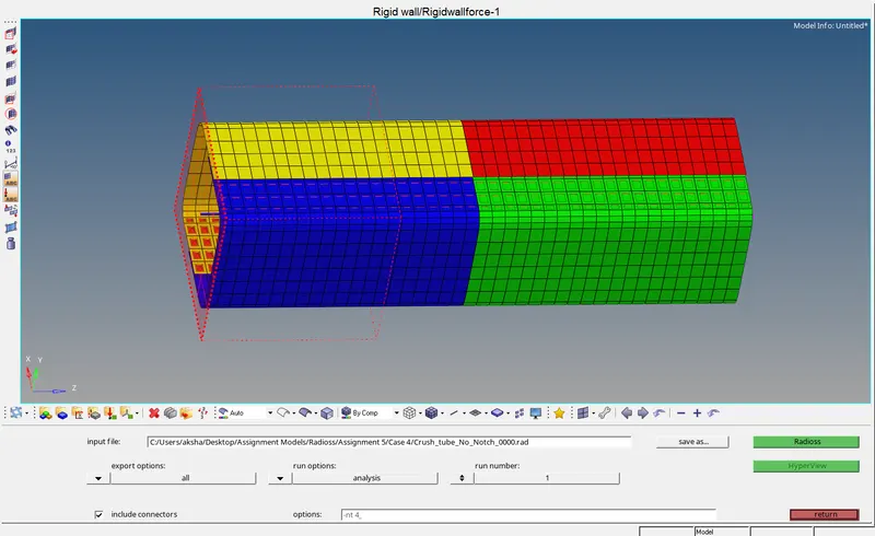
Run the analysis with 4 cores and include connectors as shown below:
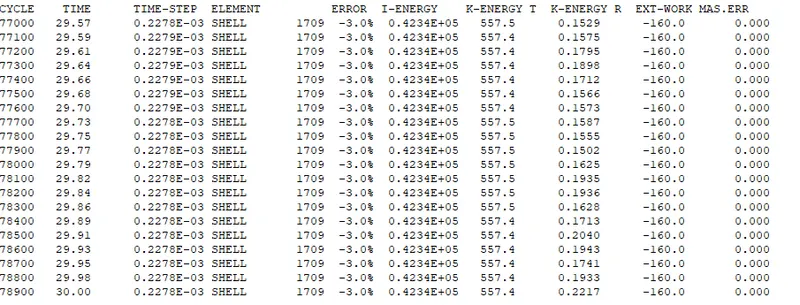
The energy error is -3.0% & the mass error is 0 which is in an acceptable range.
Next, we switch to hyper view & hypergraph to run the simulation, view contour plot & Energy Graphs Respectively:
The energy graphs are as shown below:

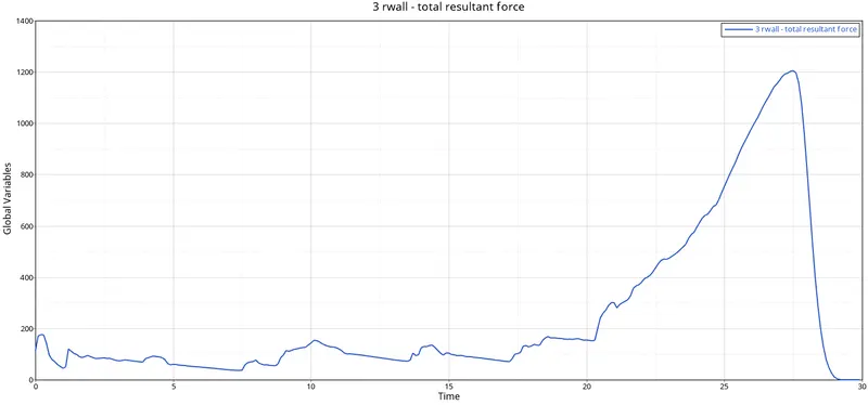
The rigid wall forces are as shown below:
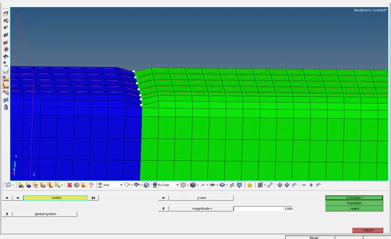
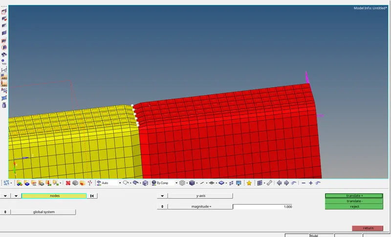
Case 5: Creating a notch in the middle and running the simulation:
The notches are created by the align panel as shown below:
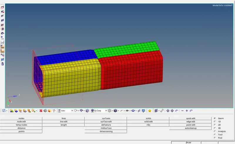
The analysis is run as shown below:
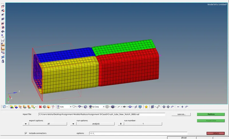

The energy error is -3.9% & the mass error is 0 which is in an acceptable range.
Next, we switch to hyper view & hypergraph to run the simulation, view contour plot & Energy Graphs Respectively:
Energy Graphs are as shown below:
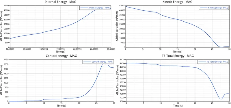
Rigid wall forces are as shown below:
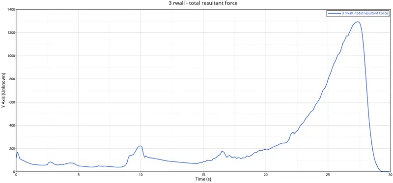
Case 6: Create new notches on opposite faces:
Create notches by the align panel as shown below:
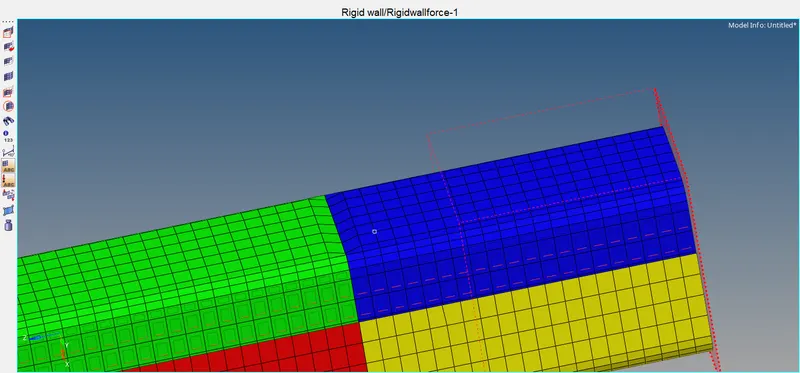
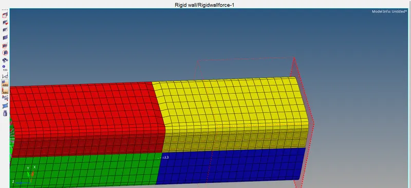
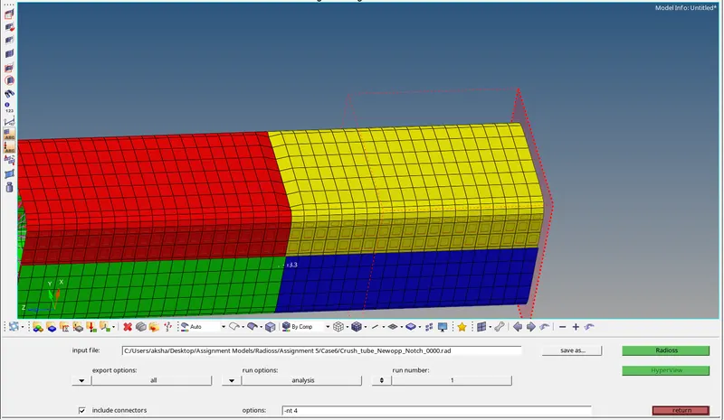
Run the analysis as shown below:
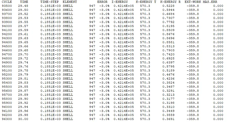
The energy error is -3.0% & the mass error is 0 which is in an acceptable range.
Next, we switch to hyper view & hypergraph to run the simulation, view contour plot & Energy Graphs Respectively:
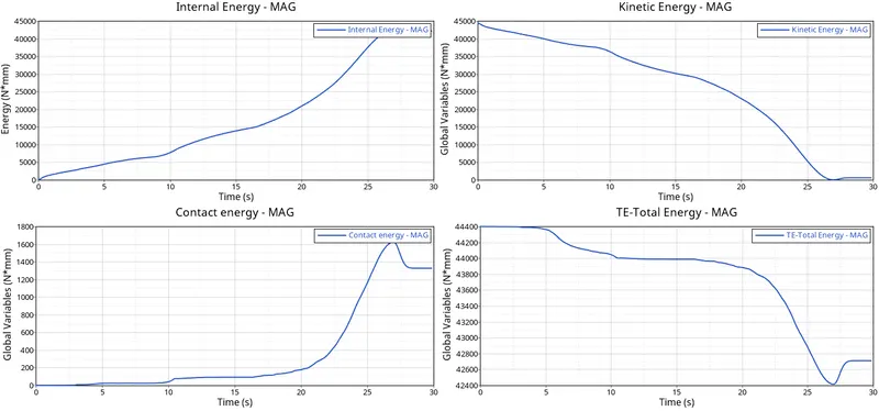
Energy graphs are as shown below:
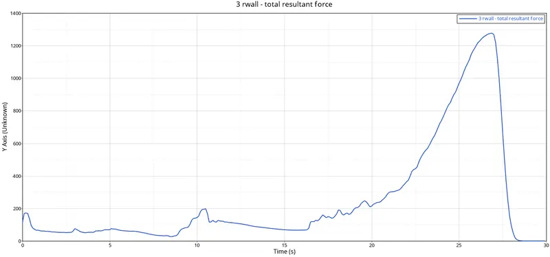
Rigid wall forces are as shown below:
Result:
| S.No. | Objectives | Energy Error (%) | Mass Error (%) | Max. Rigid wall force (N) | Max. Contact Energy (KJ) | Observations |
| Case 1 | Run Simulation without any changes | -3.8 | 0 | 1338 | 1.985 | Type 7 Contact is used. (Node to Surface) |
| Case 2 | Change the Inacti = 6 & Run | -3.8 | 0 | 1338 | 2.02 | Inacti=6, removes initial penetrations. |
| Case 3 | Create type 11 & Run | -3.8 | 0 | 1300 | 1.9 | No penetrations as Type 11 Contact is used, (edge to edge) |
| Case 4 | Remove both notches & Boundary Conditions | -3.9 | 0 | 1204 | 1.56 | The Boundary Conditions have been removed |
| Case 5 | Create a New Notch in the middle & run | -3.0 | 0 | 1288 | 2.2 | more energy is absorbed by the notch present in the middle. |
| Case 6 | Create a New Notch on opposing two faces and run. | -3.0 | 0 | 1277 | 1.6 | 2 notches are created on opposing faces which cause element intersection. |