Assignment 5-RADIOSS Interfaces & Study of Effect of Notches Challenge
RADIOSS INTERFACE AND STUDY OF NOTCHES
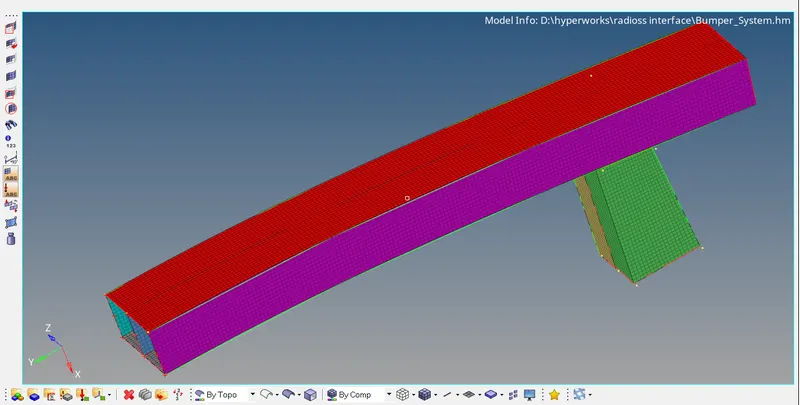
OBJECTIVE: 1) Mesh the given bumper model.
2)To study the interface of radioss and to observe the affect of notches in the component.
1)BUMPER MESHING EXERCISE:
IMAGE OF THE MESHED BUMPER.
2)SETUP OF THE MODEL AND RUNNING THE MODEL:
Before we run the solver we create a th part file in the solver browser and select all the 4 componenets in entity id slot.
To run a model we go to the analysis tab and hit radioss. Now we give the number of core as -nt 4 and save the file. Check the include connectors box and hit radioss to run the model. Follow this procedure for all the cases to run the simulation.
CASE1:
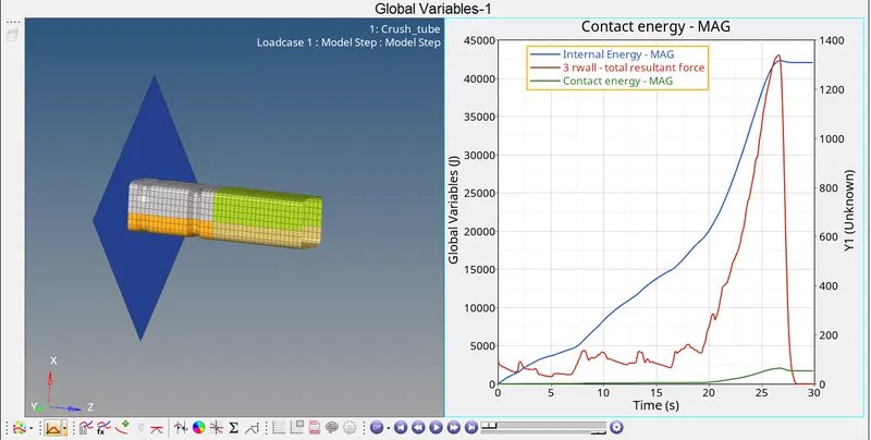
In this case we run the given model as it is and plot the graph using hypergraph 2d.
The below image depicts the images of simulation and the graphs.
Results:
1)when the animation is run we can observe that the notches get deformed first , followed by the other part of the component body.
2)From the graphs plotted we can observe that the internal energy varies increasingly upto to 25s and after that it remains almost constant.
3) contact energy remains upto 20 seconds and then shows a slight variation.
4)rwall resultant force varies continously till 25 seconds and then rapidly falls to 0 at the end of 30 seconds.
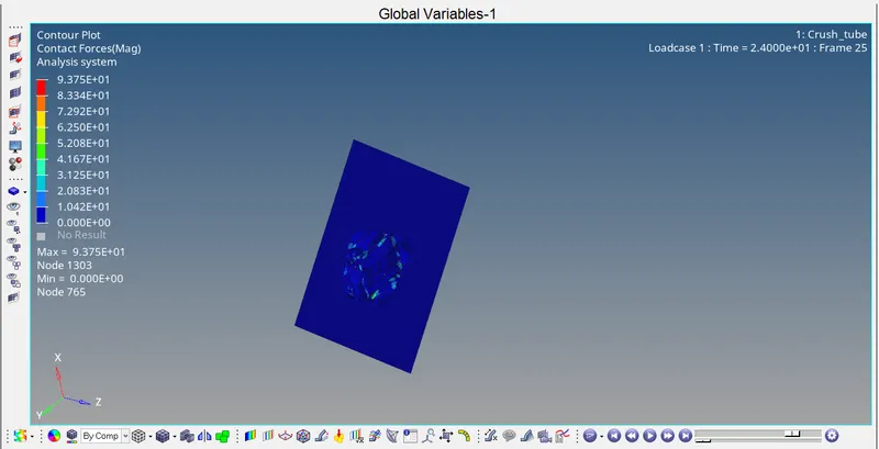
5)The contour plot for contact force is shown below:
MAX contact force = 9.375e01
CASE2:
In this case we change the inacti to 6. For this we go to model broswer and expand the groups tab. Now under the self contact we change the inacti to 6 and run the simulation.
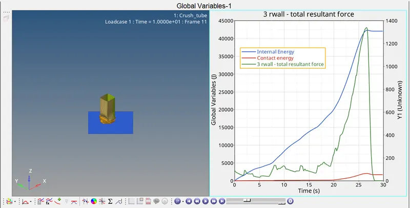
The below image depicts the images of simulation and the graphs.
Results:
1) when the animation is run we observe similar results to that of the first case, the notches get crushed first , followed by the body of the component.
2) inacti is a parameter used to take action if initial penetration exists. Inacti 6 reduces the gap and scales it up, hence giving good accuracy in the results.
3) The obtained results have good accuracy compared to that of the results in the first case due to take inacti 6 parameter.
4) internal energy increases upto to 25 seconds and then remains constant.
5)The contour plot for contact force is shown below:
MAX contact force = 9.375 e01
CASE3:
In this case we create the type 11 contact and run the simulation.
For type 11 contact we have to enter certain recomended parameters. The recomended parameters are mentioned below:
istif=4
igap=3
idel=2
stmin=1
inform=2
fric=0.2
gapmin=1
inacti=6
once we set these parameters we are good to run the simulation.
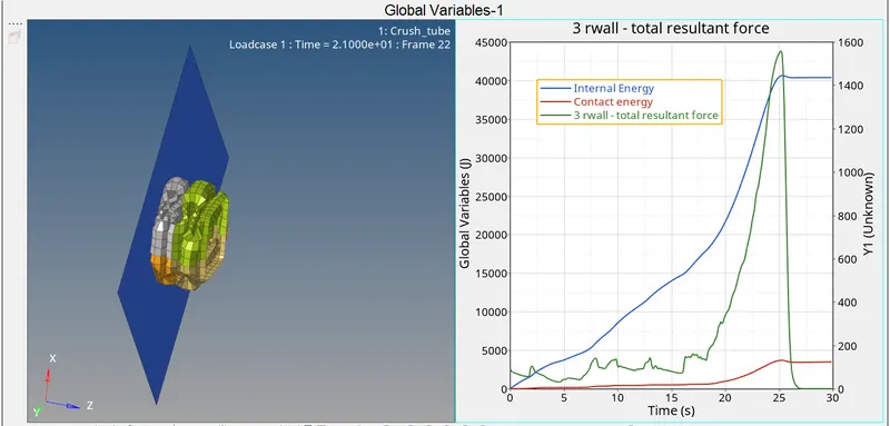
The below image depicts the images of simulation and the graphs.
Results:
1)Type 11 : edge to edge contact. This interface simulates impact between edge to edge or lines. A line can be a beam or shell or spring or truss element. This uses complicated mathematical algorithm and is recommended to use only when required.
2) When the animation is run we observe results similar to that of the above cases.
3)The internal energy reaches a value of 40000 at the 30th second.
4) we can observe that there is a rise in the contact energy as compared to the previous two cases.
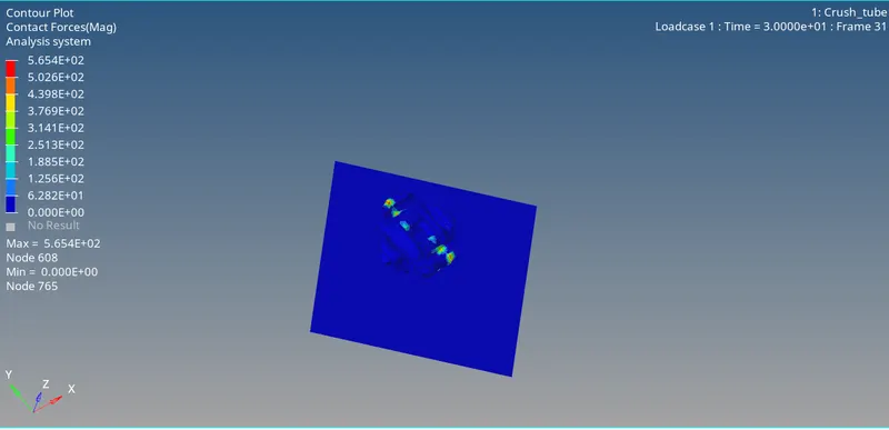
5)The contour plot for contact force is shown below:
MAX contact foce = 5.65e02
CASE4:
In this case we remove both the notches and also remove the boundary condition at the rigid node and then run the model.
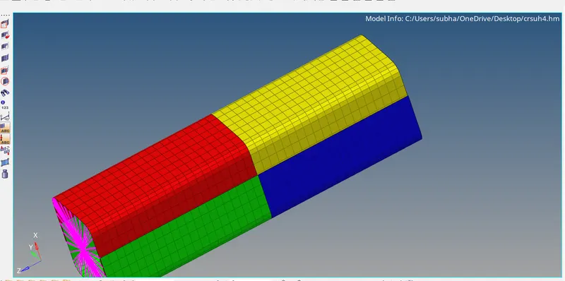
To remove the notches we make use of the allign node under the node edit tab.
To remove the boundary condition we go to solver browser and open the boundary condition tab and delete it.
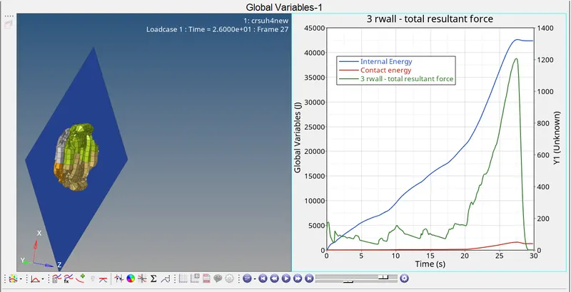
The below image depicts the images of model,simulation and the graphs.
Model after removing the notches:
Graph and simulation:
Results:
1) From the above plot we can observe that 4200 is the maximum internal energy generated for crushing the tube on the rigid wall.
2)1200 is the maximum resultant force. after 25seconds there is a rapid decrease in the resultant forces.
3)2500 is the maximum contact energy obtained from the above plot.
4) The contour plot for contact force is shown below:
MAX contact force=6.09e01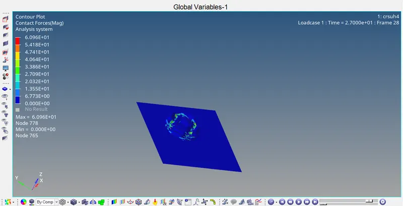
CASE 5:
In this case we create a new notch at the midde of the crush tube. This can be done using two ways.
1) we can make use of the translate option.
2) we can make use of the allign node option.
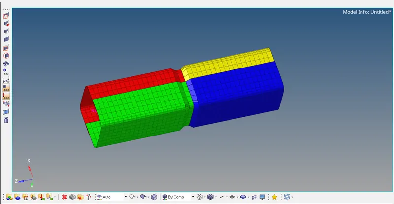
I have used the allign node option since i found it easier to create the notch at the curved edges. In this we open the default crush tube file and use the old notches to create a new notch at the center of the tube.
once the new notch is created we delete the old notches.
The model is shown below:
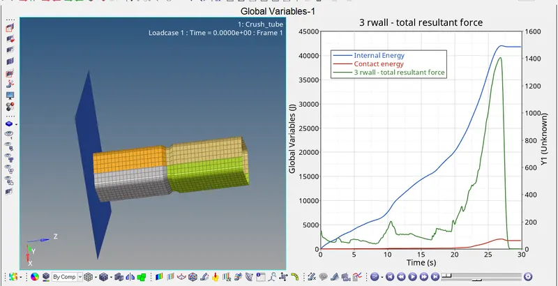
The below images depicts the graphs and simulation images of the tube:
Results:
1) The internal energy goes upto a maximum value of 4250. After the element is fully crashed some opposite forces will be generated because of which some amount of kinetic energy increases and the total energy remain unstable.
2)The contact energy reaches a maximum value of around 2500 and falls down slightly at the end of 30th second.
3) The total force goes somwhere close to 38000 and then falls down rapidly as it nears the 30th second.
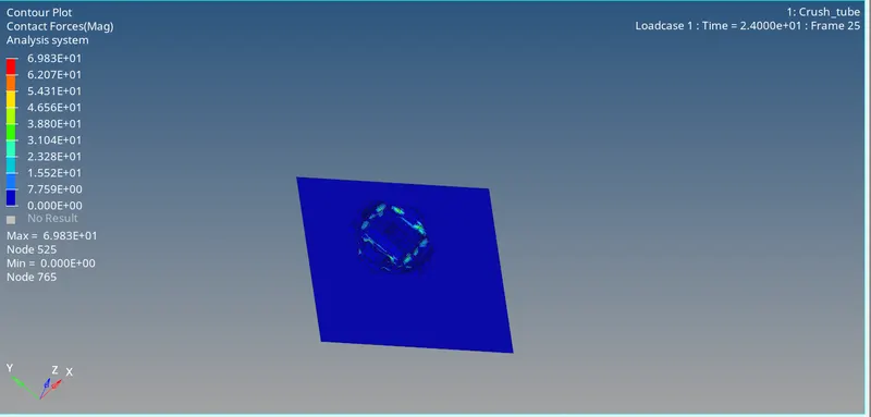
4)The contour plot for contact force is shown below:
MAX contact force = 6.98e01
CASE 6:
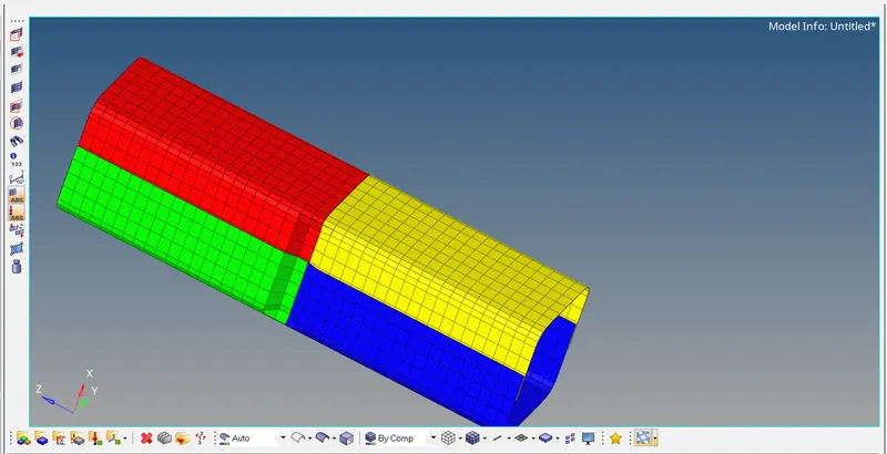
In this case we create notches with nodes only the opposite2faces. For this we can once again make use of two methods as mentioned above in CASE 5. But i have used the second method ( allign node) to set up the model.
The below pic shows the model after editing:
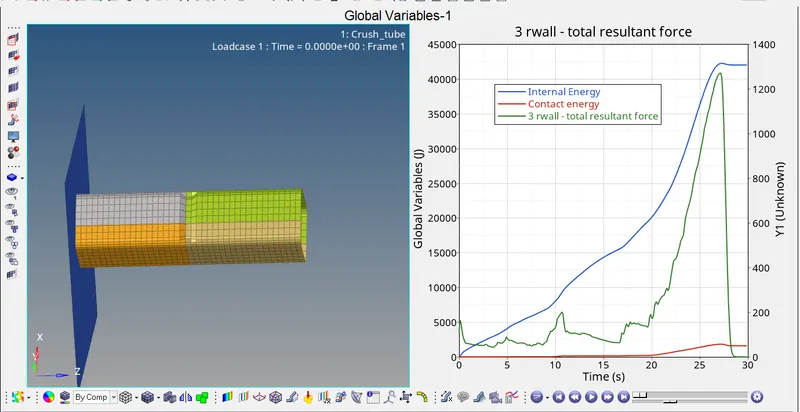
The below images depicts the simulation and graph plots of the model:
RESULTS:
1)The internal energy goes upto a maximum value of 4250 once again.
2)the total resultant forces increases upto 42000 and then undergoes a rapid downfall.
3)The contact energy stays somewhere around 2000 at the end of 30th second.
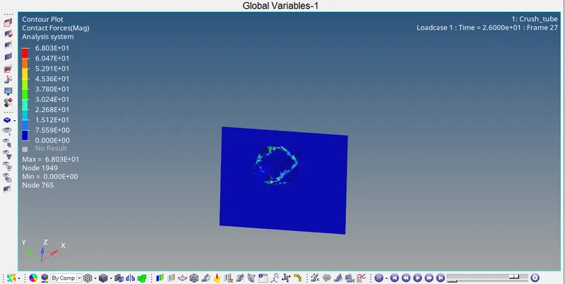
4) The contour plot of contact force is shown below:
MAX contact force = 6.8e01
CONCLUSION:
Total of two studies were being done:
1) Meshing of the bumper with element size =6mm
2) Radioss interface study for 6 cases:
a) Simulate the model as it is (type 7 contact)
b) inacti=6(type7) and run the model.
c)Create type 11 contact and enter recomended parameters and run the model.
d) remove the notches and run the model.
e) Create a notch in the middle and run.
f) create notch only in nodes facing opposite 2 faces.
Results plotted: Rwall forces, contact energy and forces, internal energy.
Files attatches :
1)Bumped mesh file.
2) Zip folder with all the simulation files. The zip folder contains indivual subfolder (crush1, crush2, crush 3, etc) inside which there will be the simulation files.