Assignment 5-RADIOSS Interfaces & Study of Effect of Notches Challenge
RADIOSS Interfaces & Study of Effect of Notches
Objective: To create the mesh for bumper assembly, study the radioss interfaces, and the effect of notches.
Problem Specification:
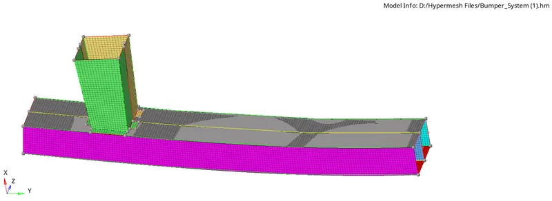
- Create the mesh for bumper assembly, mesh size should be 6mm.
- Run the crash tube model as it is.
- Change the Inacti=6 and run.
- Create the type 11 contact and run.
- Remove both notches and remove boundary condition on rigid body node then run.
- Create a new notch in the middle, select the whole section and run.
- Create a new notch with nodes only from opposing 2 faces and run.
Theory:-
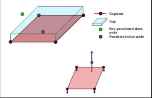
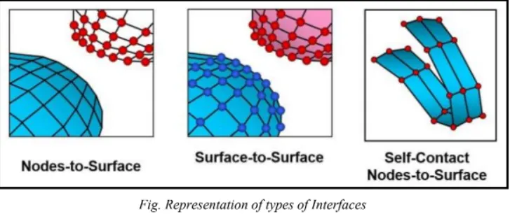
Intefaces are defined to model how parts interact when they come into contact with each other. Penalty method is used in the interfaces. It treats master and slave segments as spring that generate resistive forces as a function of penetration.
Interface Type7:
It is a general purpose interface which can simulate all types of impact between set of nodes and master surface. Major advantage of type 7 interface is that it is non orientated and slave nodes can belong to the master surface enabling the self impact. Following are the recommended parameters of the Type7 contact
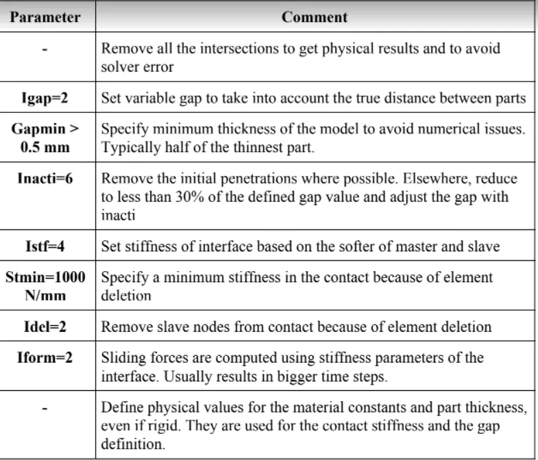
One of the drawbacks of Type7 contact is that it can not remove the element intersection that is present in the model. To avoid that kind of issue and edge related intersections, Type11 contact is preferred. Type 11 works very much similar to that of Type7 but the search is for only the edge of the model.
Procedure:
Model-1
- Import the model in Hypermesh
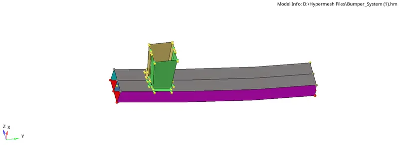
- Switch to Topo mode
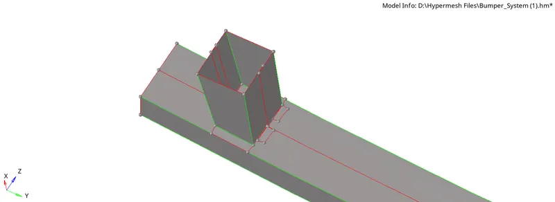
- Fix the free edges using surface edit tools.
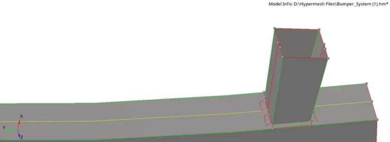
- Specify the target element size of 6 mm in the criteria file setting then enter F12 to go to the auto mesh panel and perform the meshing surface by surface.
- Now connect the crash boxes with the bumper using a spot weld. Go to 1D>Connectors> spot in the location selector and select the nodes of the crash box. Enter no of layers =2 and search tolerance as 3.0. Select type as weld with diameter =2 and click create. Similarly, connect the crash boxes.
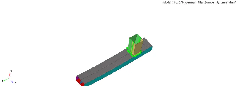
This concludes the meshing in the bumper assembly.
Simulation Exercise
Case1(Run the crash tube model as it is)
- Open the Hypermesh and select the user profile as Radioss.
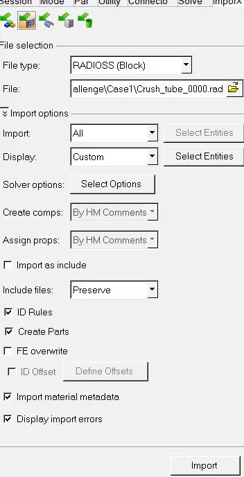
- Import the given 0000.rad file.
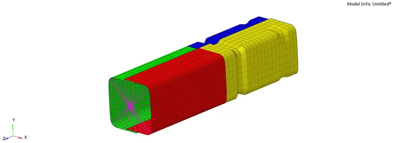
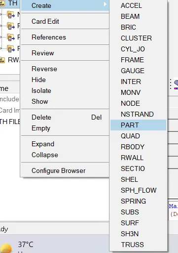
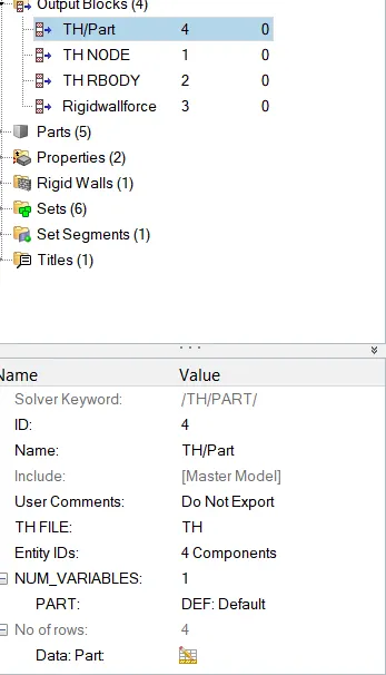
- Create TH/PART. Go to Solve>TH>Create>Part. Select all the components.
- Now run the simulation Go to Analysis>Input file>Include connector>Options= -nt 4

- Open. out engine file from the saved folder and check the final value of energy error, mass error, simulation time, and total no of cycles.
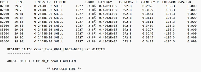
( In this case, the energy error and mass error are in the acceptable range)
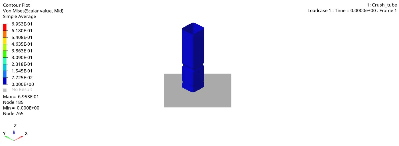
- Plot the required curves using Hypergraph 2D and required animation using the Hyperview.
Observations
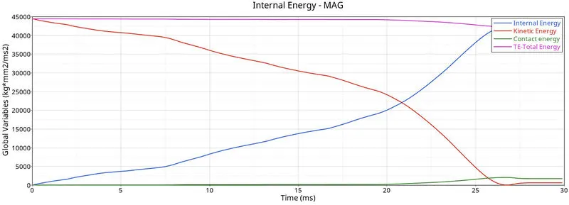
- In the beginning, kinetic energy is highest, but it gradually decreases with time as it gets converted into strain energy (Internal energy) as the tube is crushed.
- Total energy remains constant for most of the time but there is slight drop at time t=25 ms because the tube is totally crushed and energy is lost to the friction between the elements.
- Contact energy = contact force* distance moved to avoid penetration it is the energy which enables contact force to avoid penetration.
- The contact energy is very low most of the time, but it rapidly increases after 20 ms since the tube has completed deformation after 20 ms, which causes a force to crush the surface of the tube in the formation of layers.
- As the corner surfaces come into contact with each other, they form a spring that prevents them from intersecting.
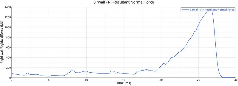
- Concerning the rigid wall force, there is an abrupt increase in peak value once at T=25 ms. However, after 25 ms the tube has already been crushed and the deformed model has no further room for deformation therefore it reduces to zero.
Case2(Change the Inacti=6 and run)
- To change Inacti to 6 Go to Solver>Inter>Type7>Inacti=6
- It will remove any initial penetration present.
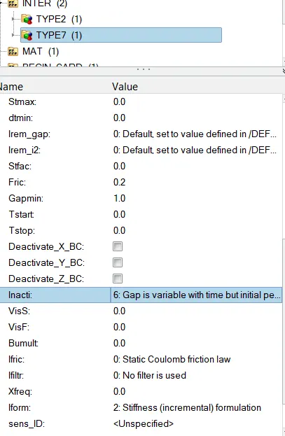
- After this run, the simulation procedure is the same as discussed earlier.
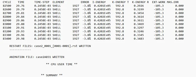
( In this case, also the energy error(-3.8%) and mass error (0) are in the acceptable range)
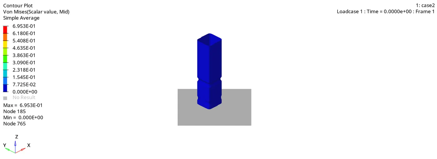
The plots are similar in nature compared to case 1.
Case3(Create the type 11 contact and run)
- Create the Type 11 contact.
- Set the parameters as follows.
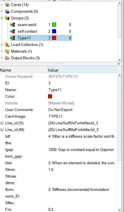
- After this run, the simulation procedure is the same as discussed earlier.
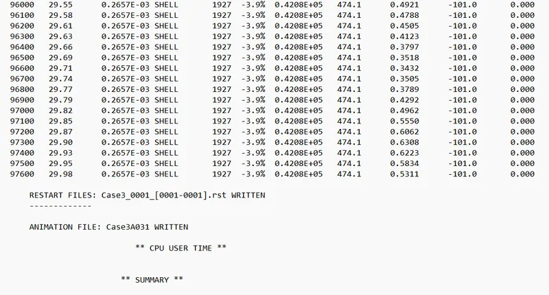
( In this case, also the energy error(-3.9%) and mass error (0) are in the acceptable range)
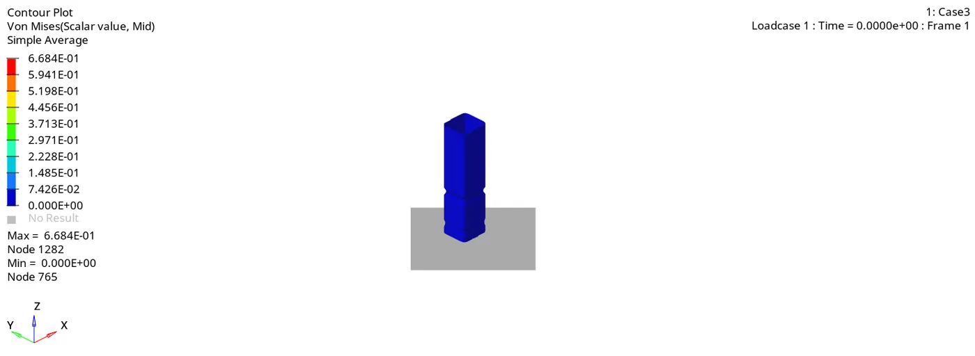
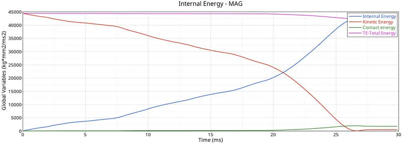
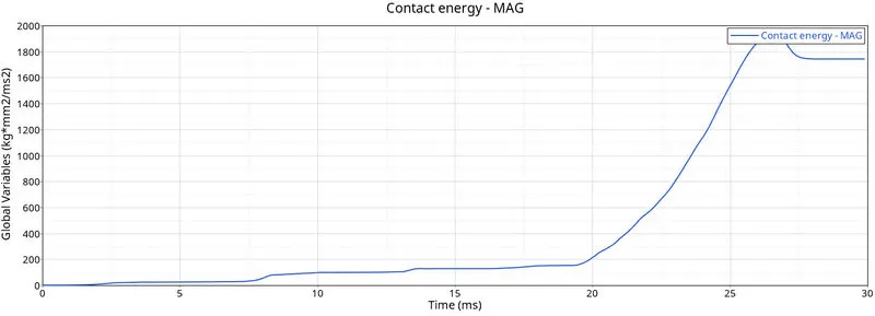
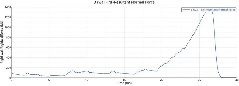
- Here too the nature of deformation and energy graphs nature is similar to the previous case.
Case 4 (Remove both notches and remove boundary condition on rigid body node then run)
- Open the Hypermesh and select the user profile as Radioss.
- Import the 0000.rad file.
- Use the node align option to remove the notches.
- Go to the solver and delete the boundary condition card.
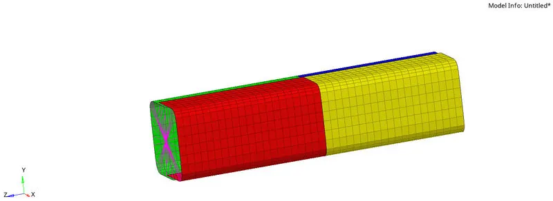
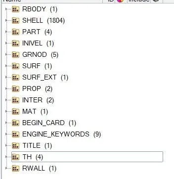
- After this run, the simulation procedure is the same as discussed earlier.
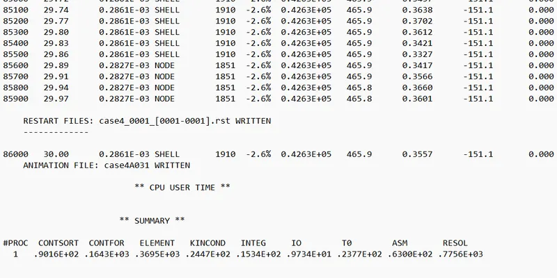
( In this case, also the energy error(-2.6%) and mass error (0) are in the acceptable range)
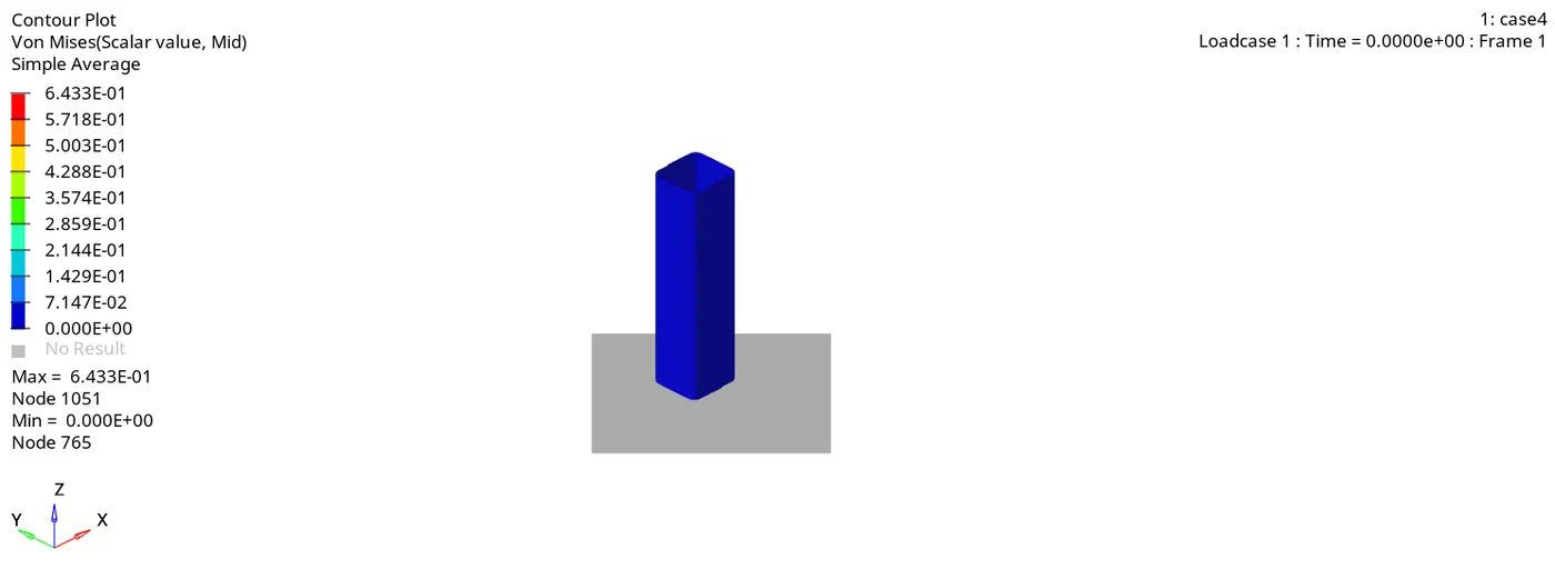
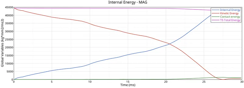
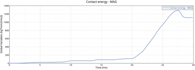
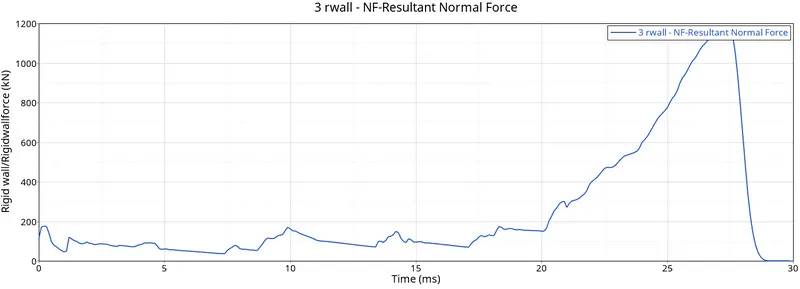
- As there are no notches present therefore no localized deformation is observed and the value of contact energy is also less compared to the previous case. The energy graph's nature is similar to the previous case.
Case5(Create a new notch in the middle, select the whole section and run)
- Open the Hypermesh and select the user profile as Radioss.
- Import the 0000.rad file.
- Use the translate option to create the new notches in the middle.
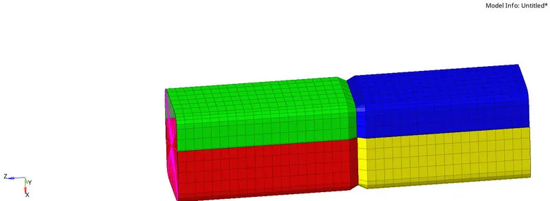
- After this run, the simulation procedure is the same as discussed earlier.
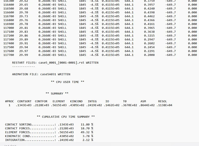
- ( In this case, also the energy error(-4.5%) and mass error (0) are in the acceptable range)
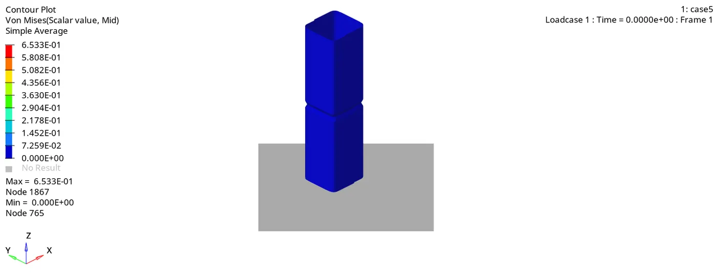
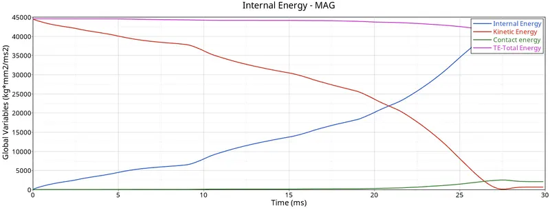
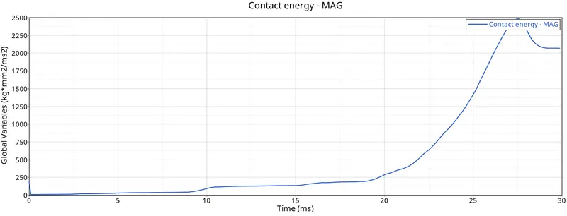
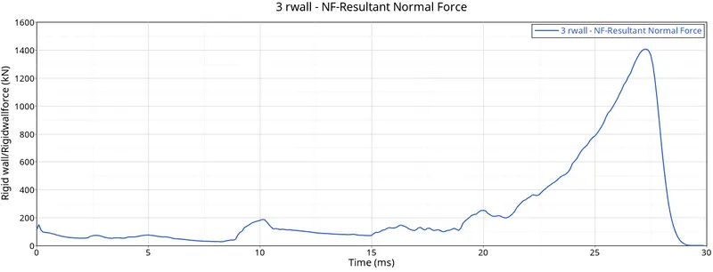
Here too the nature of deformation and energy graphs nature is similar to the previous case. The value of contact energy is more as compared to the previous case because of the presence of notches in the middle.
Case6 (Create a new notch with nodes only from opposing 2 faces and run)
- Open the Hypermesh and select the user profile as Radioss.
- Import the 0000.rad file.
- Use the translate option to create a new notch in the opposing two faces using translate option
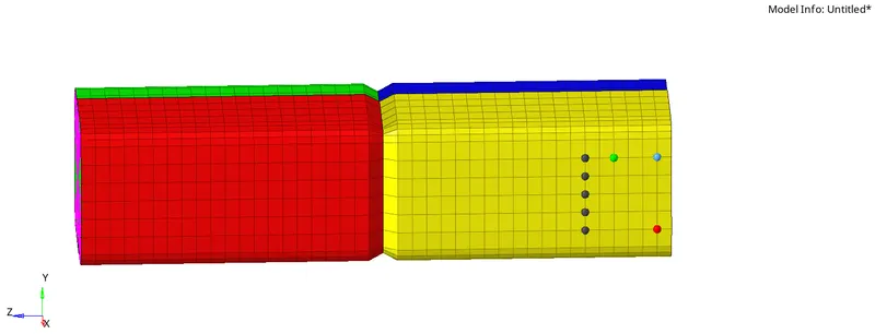
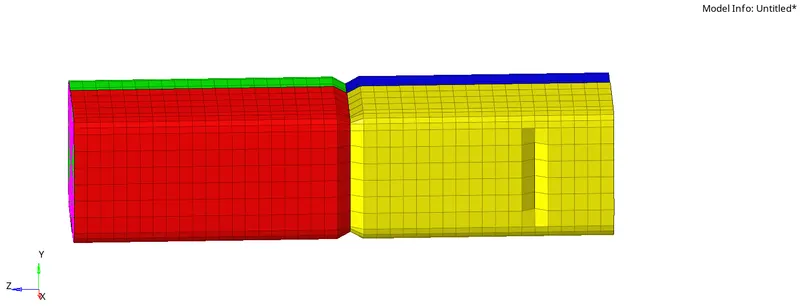
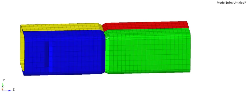
- After this run, the simulation procedure is the same as discussed earlier.
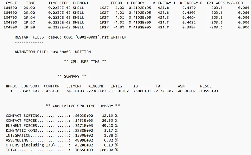
( In this case, also the energy error(-4.0%) and mass error (0) are in the acceptable range)
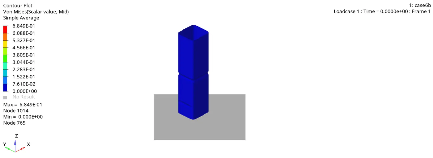
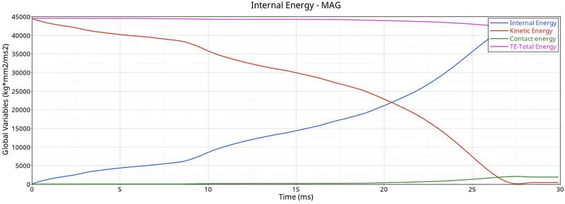
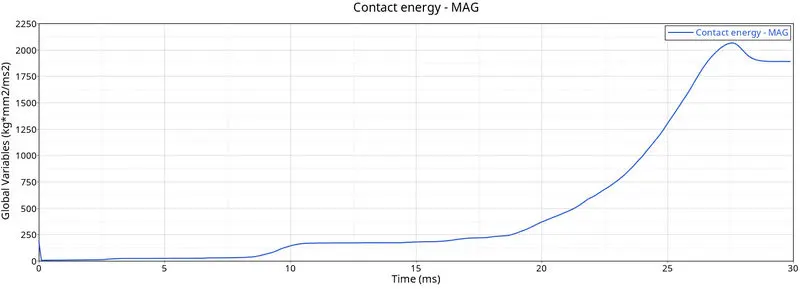
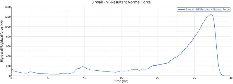
In this case, the deformation is first observed at the notched region and the energy graphs are similar in nature compared to previous cases. The value of contact energy and force is less as compared to the previous case.
Results:-
|
Case |
No of cycles |
Energy error |
Mass error |
Max von mises stress (Gpa) |
Contact interface Type |
|
1 |
83469 |
-3.8% |
0% |
0.6953 |
Type 7 |
|
2 |
83469 |
-3.8% |
0% |
0.6953 |
Type 7 |
|
3 |
97683 |
-3.9% |
0% |
0.684 |
Type 7 + Type11 |
|
4 |
86001 |
-2.6% |
0% |
0.6433 |
Type 7 + Type11 |
|
5 |
117722 |
-4.5% |
0% |
0.6533 |
Type 7 + Type11 |
|
6 |
104956 |
-4.0% |
0% |
0.6849 |
Type 7 + Type11 |
- In case 2 Inacti =6 is applied but the nature of energy graphs remains the same which indicates there was no initial penetration.
- In the third case Type, 7, and Type 11 interfaces work together increasing the no of cycles and the energy error.
- Von mises stress value is least in case 4 where notches are removed.
- Energy error for all the cases is in the acceptable range.
- In the fifth case, energy error is maximum due to the notch created at the middle section. In the sixth case, it is reduced due to notches created at the opposite faces.
Conclusion:-
- Studied the working of type 7 and type 11 interfaces in the simulation.
- Studied the effect of notches based upon their location and no of notches.
- Learned to plot the energy and rigid wall force curves.
- Studied the parameter check before the simulation and during simulation.