Assignment 5-RADIOSS Interfaces & Study of Effect of Notches Challenge
OBJECTIVE: To mesh the bumper component and deploy suitable connectors, also to run the simulations and plot the graphs for different cases.
PROCEDURE:
Step1: To import the give file to the GUI.
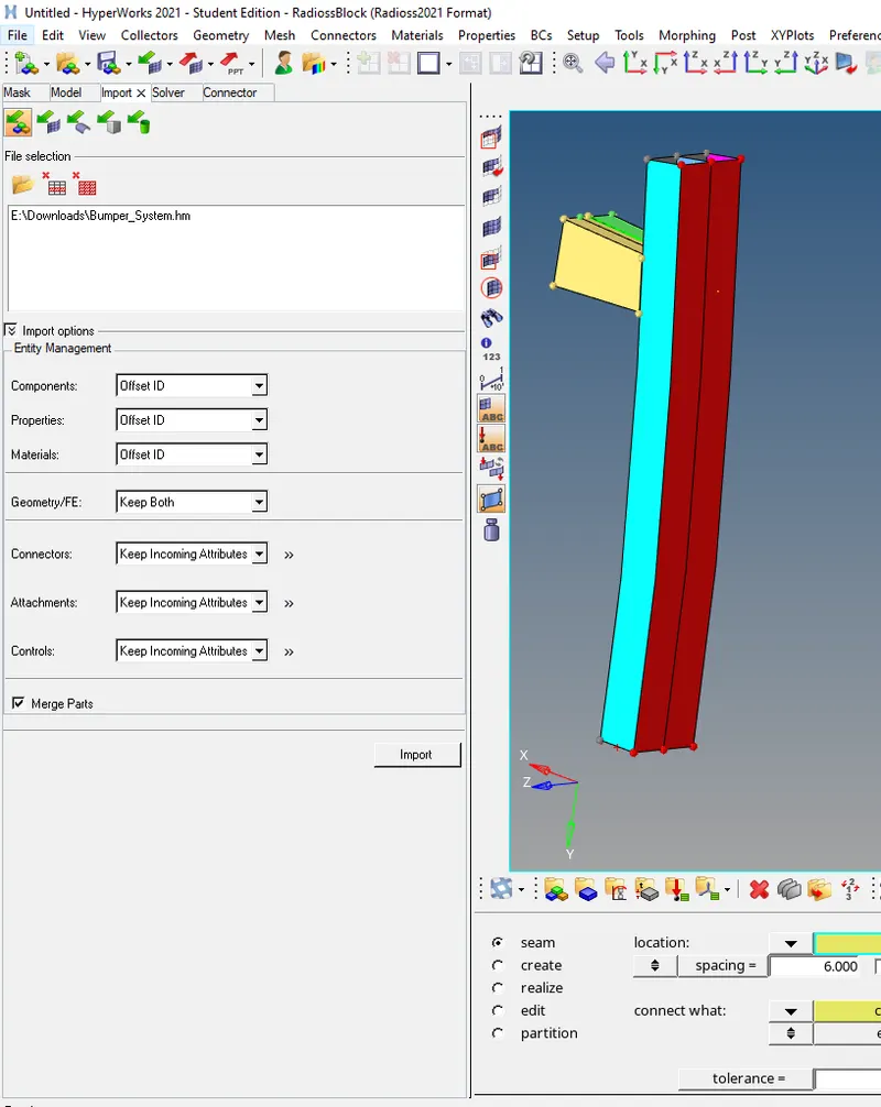
- Import> browse the Hm file> Import.
- The file is imported.
Step2: To mesh the given Model.
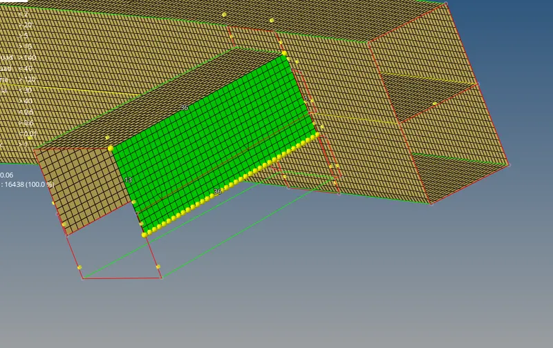
- 2D> Automesh>Size:6units>selecting the components> Mesh.
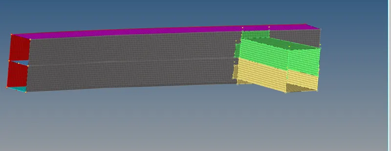
- The above componet is mesh with 6 units.
Step 3: To deploy suitable connectors to connect two diffrent parts.
SPOT WELD
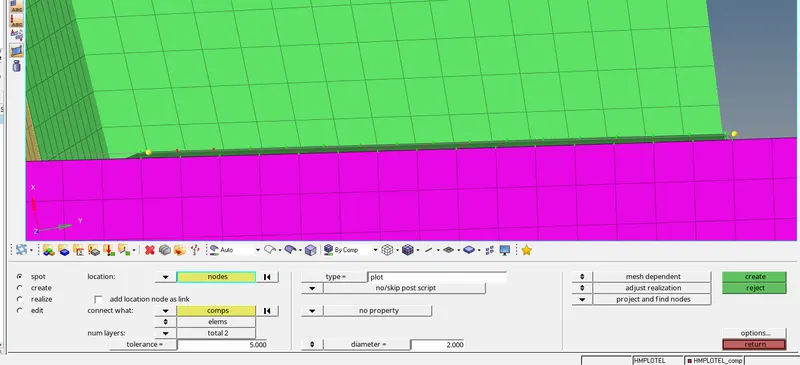
- 2D> Connectors>spot weld
- Selecting the nodes to be welded
- Providing the tolerance as wells diameter of the weld and selecting the Components, the spot weld is deployed.
SEAM WELD:
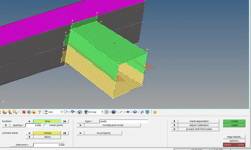
- 2D> Connectors>seam weld
- Selecting the line to be welded
- Providing the spacing as wells tolerance and selecting the Components, the seam weld is deployed.
Case 1: To Run the crash tube model as it is.
- To import the given file into the GUI.
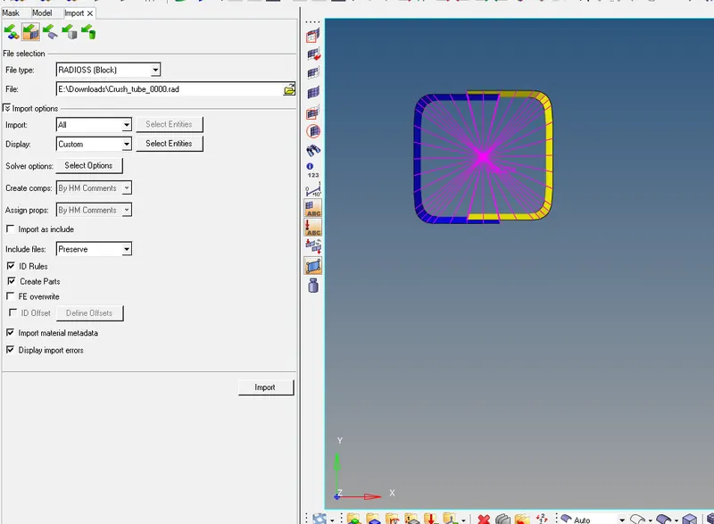
- Import>import solver deck>selecting the 0000.rad file>import.
2. To Run the Simulation without making any changes.
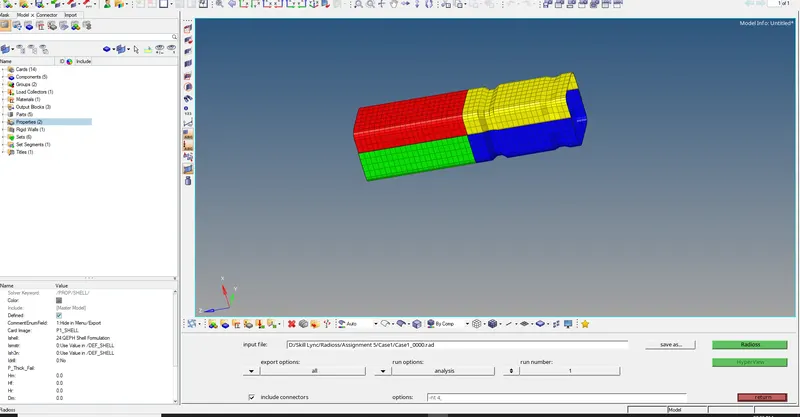
- Choosing the destination to save the simulation files.
- -nt 4 it is the command which will use all the 4 cores to run the simulation.
- Analysis>Radios>saving the file>Radioss.
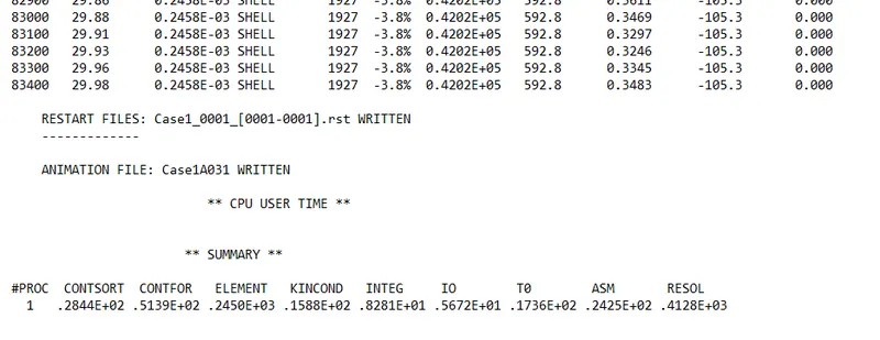
- From the above result the energy error -3.8 % which is in the acceptable range
- The mass energy error is 0.
3. Since all the Errors are falling under acceptable range now runing contour simulation for Von mises stress.
- Hyper view> selecting the h3d file to run the animation from the analysis file>apply.
- To plot Von mises and displacement stress using contour Plot
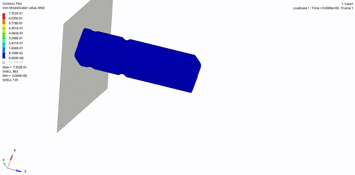
- The notch area deforms first and then followed by 2nd notch.
- The stress concentration are more in notchs.
- The irregular flow of forces causes stress concentration.
- The maximum Stress is 0.735MPA
4. To Plot Rigid WALL forces ,internal energy ,kinetic energy and contact energy for the simulations.
- Now selecting T01 file obtained from the analysis folder
- Rigid wall/ Rigid wall forces>3rwall>NF-resultant normal forces>Apply.
- Global variable> selecting internal energy ,kinetic energy and contact energy to be ploted >Mag>Apply.
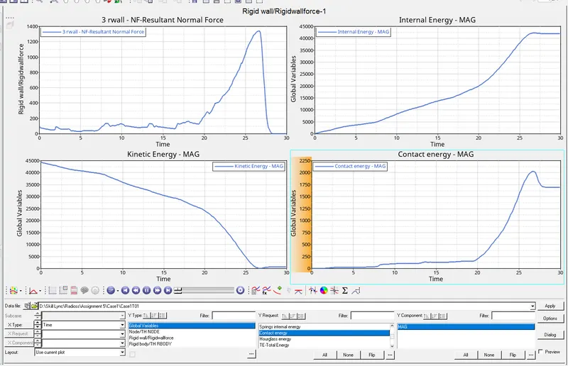
- Rigid wall Forces: The normal rigid wall forces reaches to the peak when the tube completely deforms and gets crushed to the rigid wall and the force decreses and the tube repels or moves away from the rigid wall.
- Internal Energy: The internal energy increases , reaches to maximum and becomes constant when the tubes completly deforms and gets crushed.
- Kinetic Energy: The Kinetic energy decreases and reaches to zero as the tube deforms completely and loses its energy
- Contact energy: Contact energy Increase drastically when tube is crushed completely ,reduces and becomes constant as it repels or moves away from the wall.
Case2: To make Changes in the type 7card , Inacti=6 and run the simulation.
- View>browser>hypermesh>Solver.
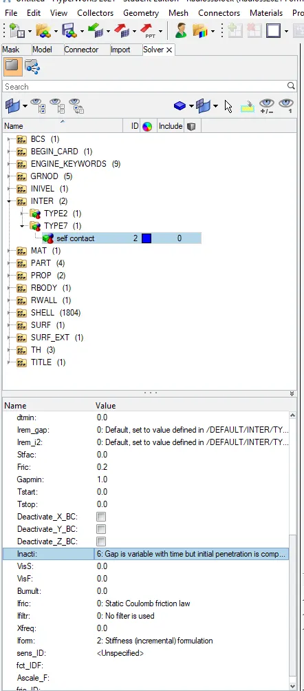
- Inter>Type7>Inacti=6, save and run.
2. After reviewing the contact interface card saving the model and runing the simulation.
- Choosing the destination to save the simulation files.
- -nt 4 it is the command which will use all the 4 cores to run the simulation.
- Analysis>Radios>saving the file>Radioss
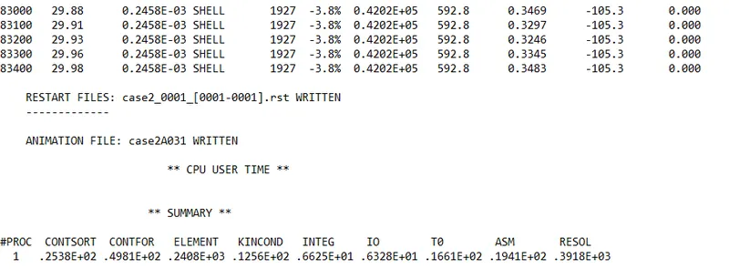
- From the above result the energy error -3.8 % which is in the acceptable range
- The mass energy error is 0.
3. Since all the Errors are falling under acceptable range now runing contour simulation for Von mises stress.
- Hyper view> selecting the h3d file to run the animation from the analysis file>apply.
- To plot Von mises and displacement stress using contour Plot
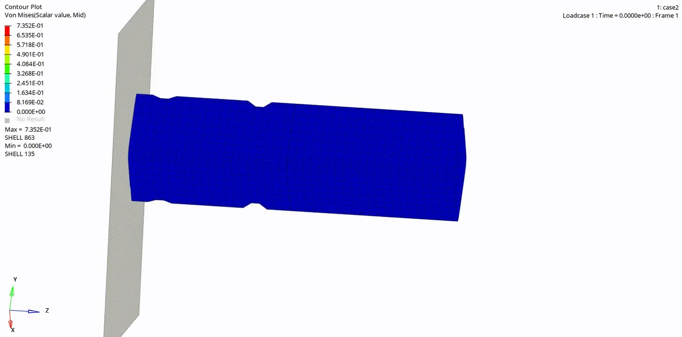
- The Deformation happens similar to the case 1 but there is no penentration as we can see the edge of the tube is curling back.
4. To Plot Rigid WALL forces ,internal energy ,kinetic energy and contact energy for the simulations.
- Now selecting T01 file obtained from the analysis folder
- Rigid wall/ Rigid wall forces>3rwall>NF-resultant normal forces>Apply.
- Global variable> selecting internal energy ,kinetic energy and contact energy to be ploted >Mag>Apply.
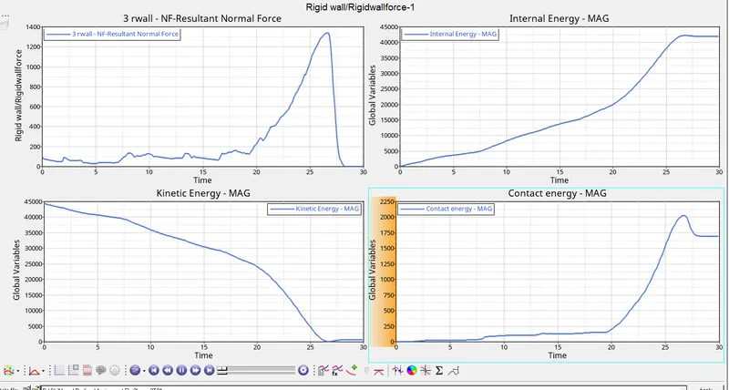
- The energy behaviour or curves are similar to the case1 there as been no changes.
Case3: To create the type 11 contact card and run the simulation.
- To create the Type 11 Card.
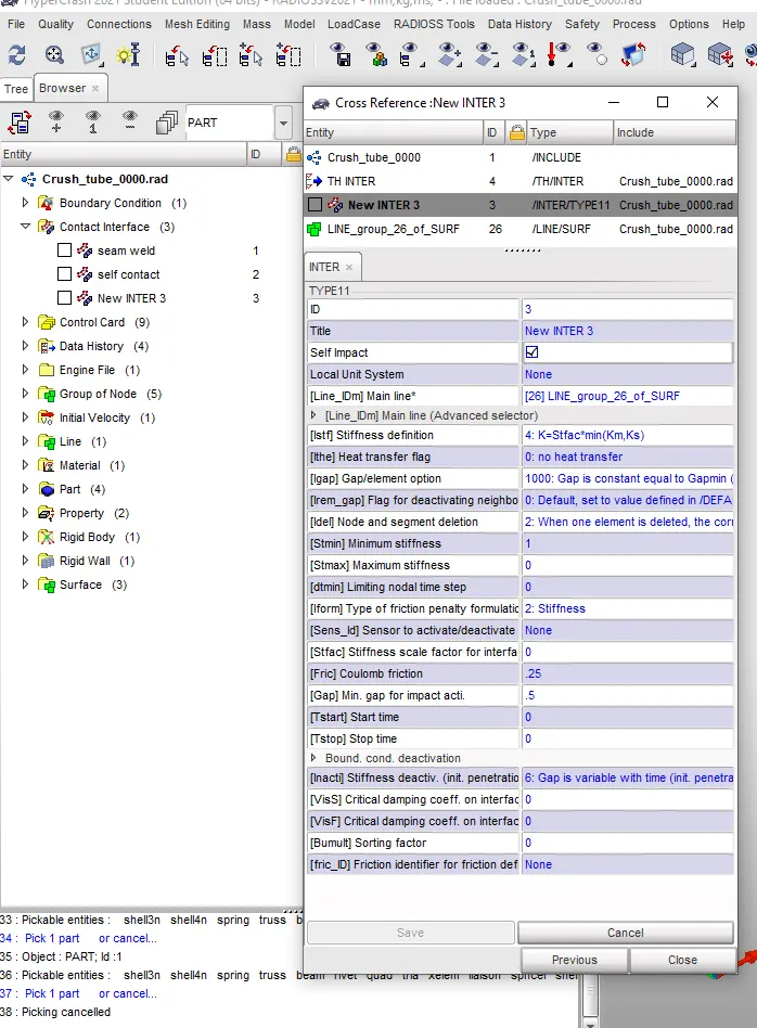
- Using hypercrash to create the type 11 card or Edge to edge.
- Hypermesh>Application>Hypercrash.
- Using drag option to import the file to hypercrash.
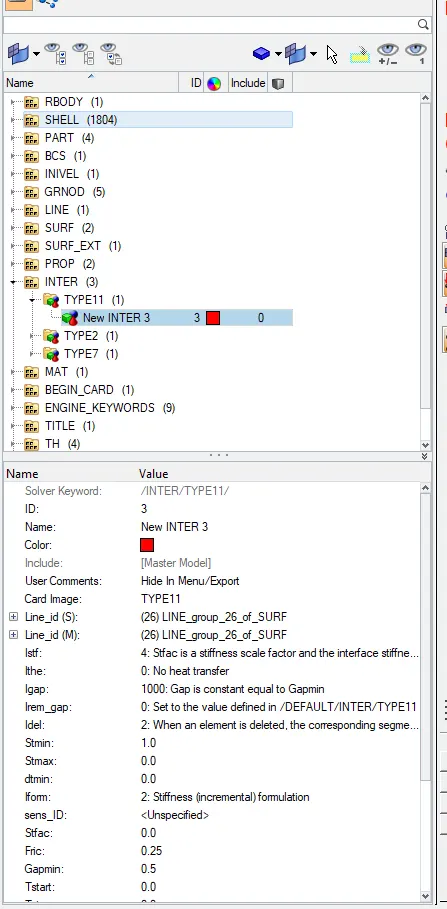
- Toolbar>Loadcase>Contact interface >right click> edge to edge type11.
- Selecting the suitable parameters.
- Then export the file and runing the file is hypermesh.
2. After reviewing the contact interface card saving the model and runing the simulation
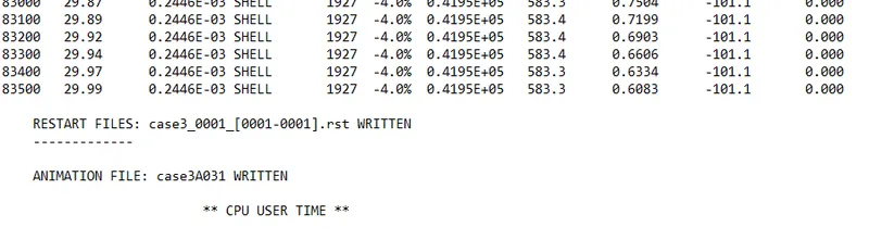
- From the above result the energy error -4.0 % which is in the acceptable range
- The mass energy error is 0.
3. Since all the Errors are falling under acceptable range now runing contour simulation for Von mises stress.
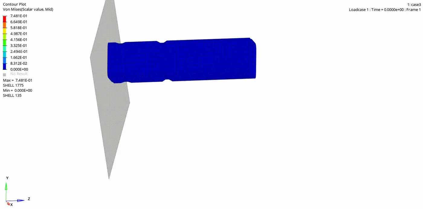
- The deformation follows the same pattern but the edge of the tube which is in contact with rigid wall curles back word just like case 2 due to penalty interface.
4. To Plot Rigid WALL forces ,internal energy ,kinetic energy and contact energy for the simulations.
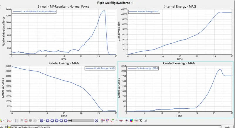
- Here there is no changes in the curve or energy.
- Follows the same behaviour in all 3 cases.
Case4: Remove both notches and remove boundary condition on rigid body node then run.
- Import the new 0000.rad file
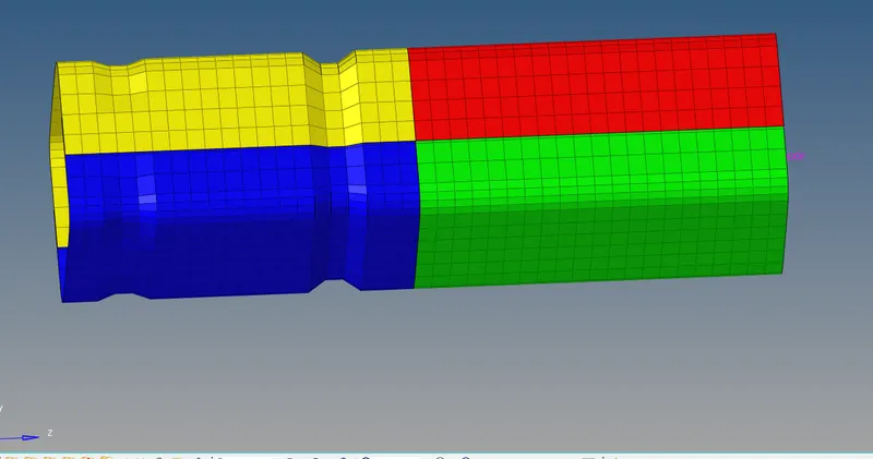
2. To remove the notch.
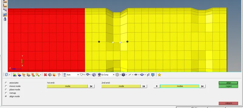
- Using Allign otion to remove the Notch
- Geom>Node edit> Align node> selecting 1st node and 2nd node for the alligning order and selecting other nodes to be alligned.
- Following the same procedure untill the notch is removed.
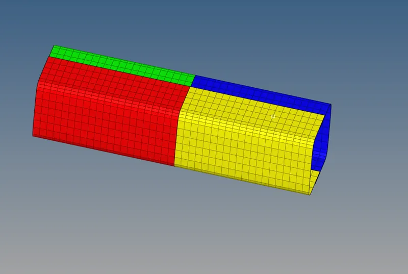
- All the notches have been removed
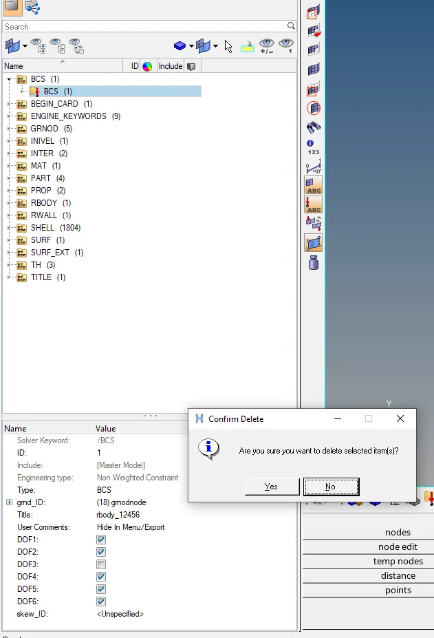
- Also deleting the boundry condition.
- Saving the file without make amy changes to contact interface cards.
3. Saving the model and runing the simulation.
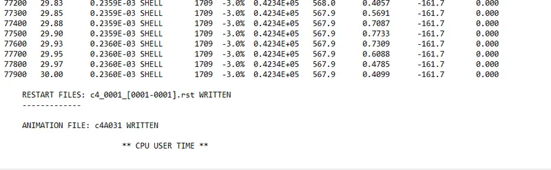
- From the above result the energy error -3.0 % which is in the acceptable range
- The mass energy error is 0.
4. Since all the Errors are falling under acceptable range now runing contour simulation for Von mises stress.
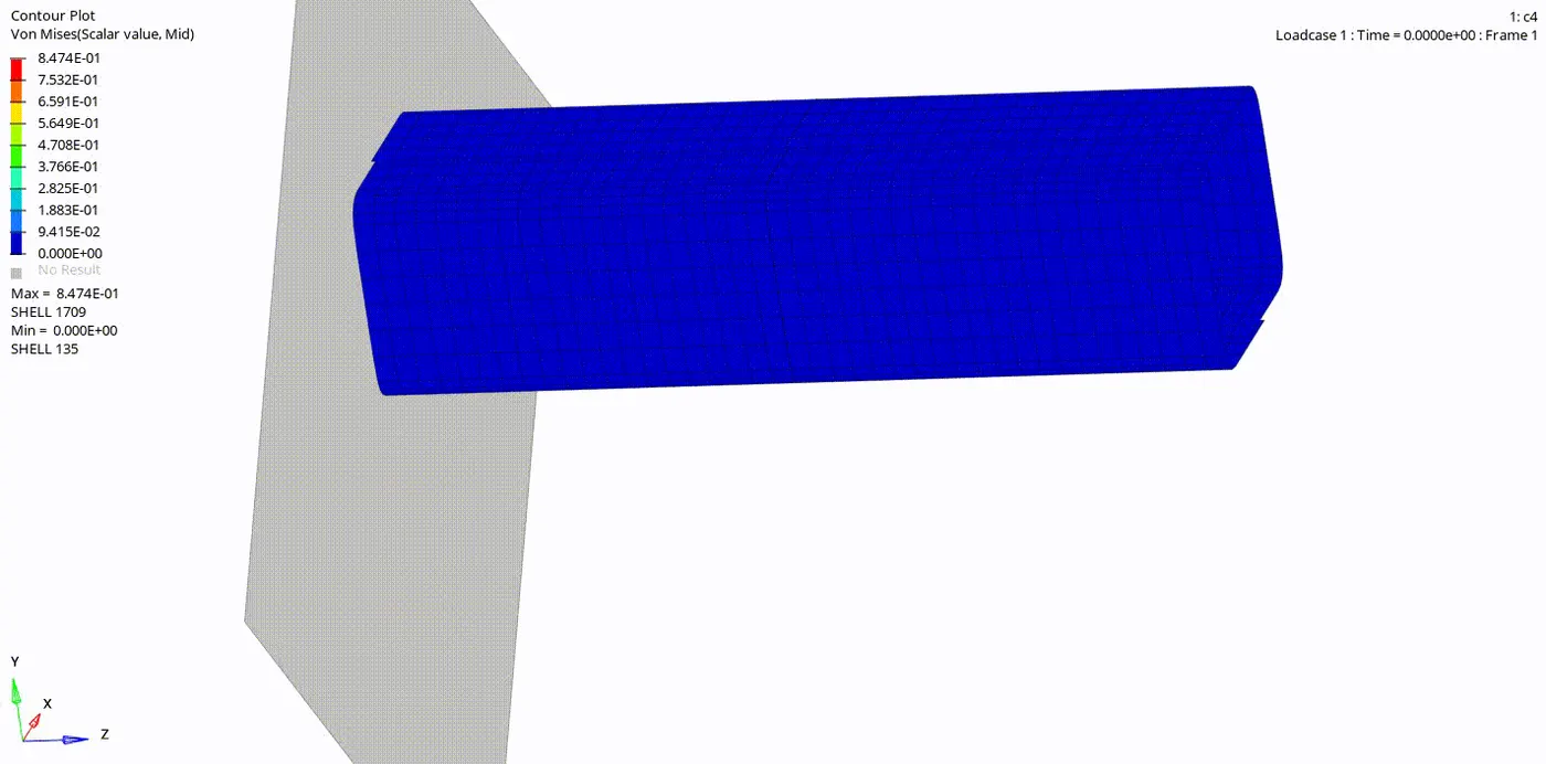
- The defomation happens in the linear way since there is no notch in the tube
- The energy is transfered from one end of the tube to the other end without any directional change.
- Maximum Von mises stress:-0.8474MPA
- Compared the previous cases the Von mises stress is more in this case.
4. To Plot Rigid WALL forces ,internal energy ,kinetic energy and contact energy for the simulations.
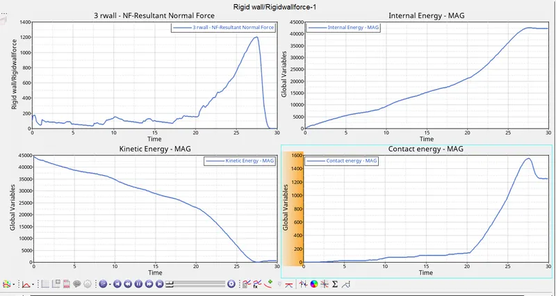
- The graphs follows the same pattern as per previous cases but the rigid wall forces and contact energy is low compare to the previous cases.
Case5:To Create a new notch in the middle and run the simulation.
- To import the previously saved file without the notes.
- Import> browse the Hm file> Import.
- The file is imported.
2. To create the notch in middle of the tube.
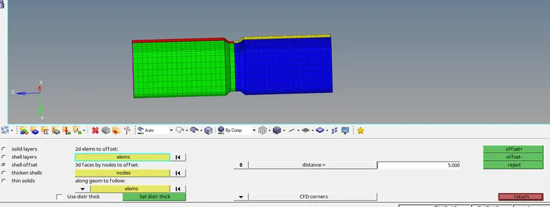
- 2D>Element offset> selecting the elements and providing the distance 5units>offset+
- The element has offset by distance 5units.
3. Saving the model and runing the simulation.
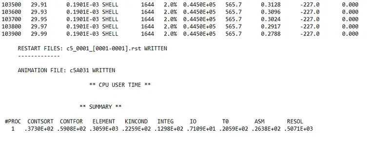
- From the above result the energy error 2.0% which is in the acceptable range
- The mass energy error is 0.
4. Since all the Errors are falling under acceptable range now runing contour simulation for Von mises stress.
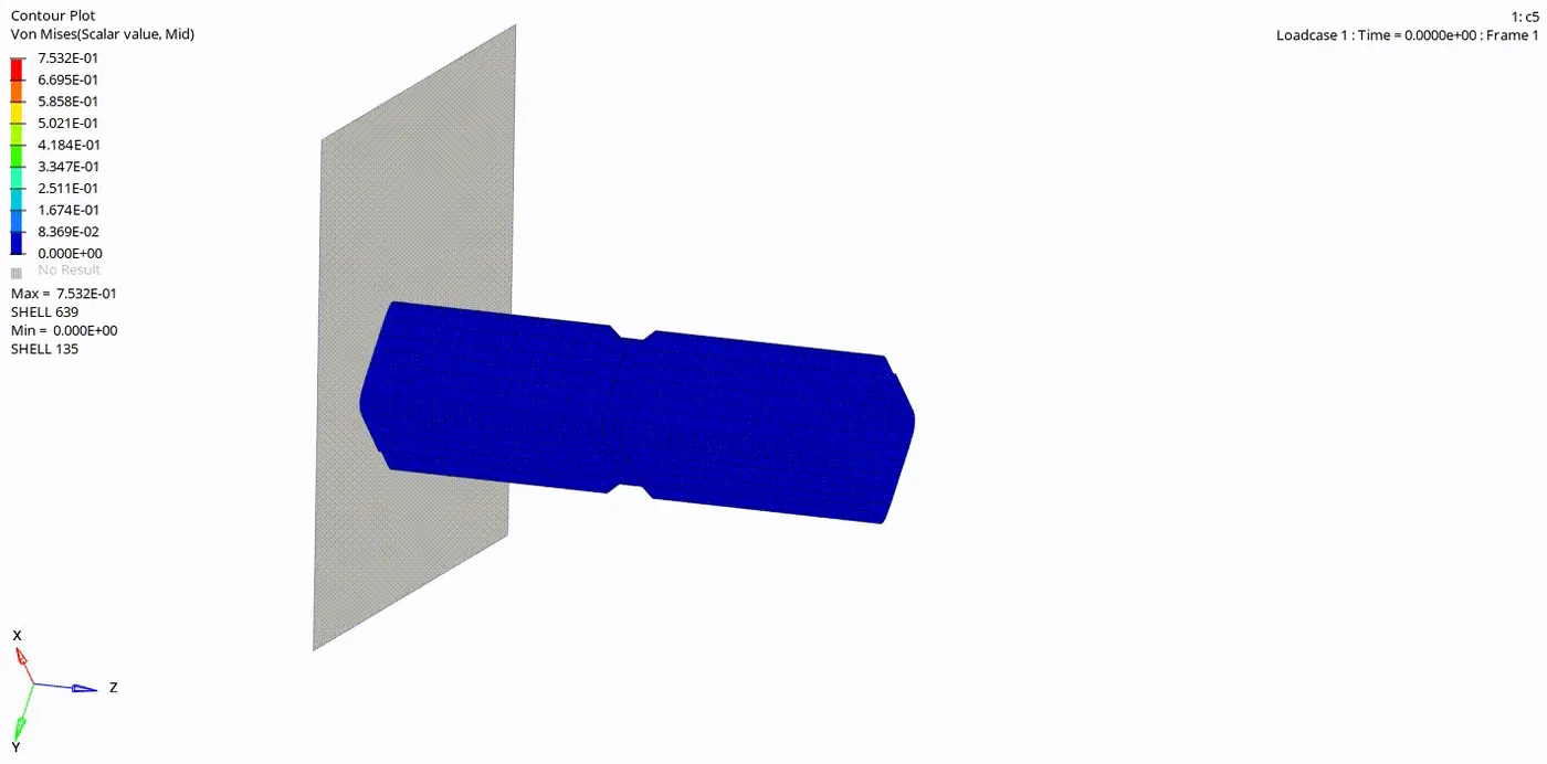
- The deformation happens at the notch and then at the edges which is in contact with the rigid wall the
- The Maximum Von mises stress is:-0.7532MPA
- The Von mises stress is more compared to the case1 , case2 and case3.
4. To Plot Rigid WALL forces ,internal energy ,kinetic energy and contact energy for the simulations.
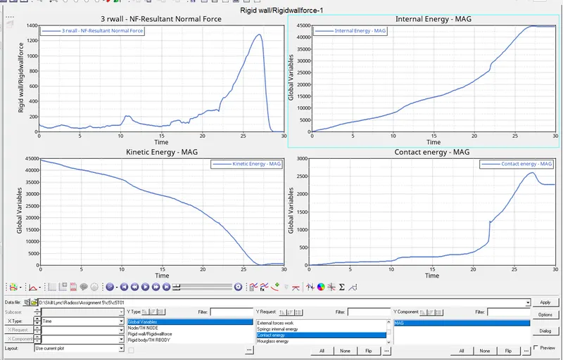
- The Internal energy has reached to maximum compared to the all other cases as well the contact energy.
Case6: To Create a new notch with nodes only from opposing 2 faces and run the simulation.
- The notch is create in the similar manner as above.
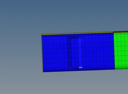
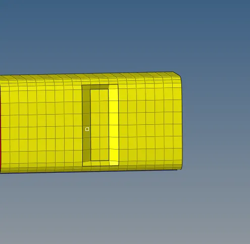
. 2. Saving the model and runing the simulation.
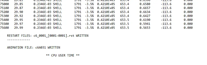
- From the above result the energy error -3.5 % which is in the acceptable range
- The mass energy error is 0.
3. Since all the Errors are falling under acceptable range now runing contour simulation for Von mises stress.
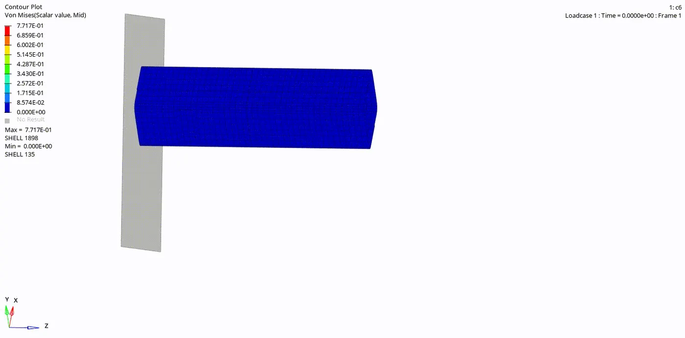
- The deformation happen in the notch.
- An then the deformation occures from below the notch to the above the notch.
- The Maximum Von mises stress is:-0.7717MPA
4. To Plot Rigid WALL forces ,internal energy ,kinetic energy and contact energy for the simulations.
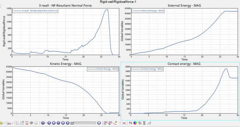
- Here the Internal energy is sightly less due to the presense of notch at both the ends because of which the tube less internal energy possessed compare to previous case.
- The rigid wall forces are is at its peak as tube deformed completely.
RESULT:
- All The Graphs follows same pattern in all the cases for diffrent energies
- From the above cases we have observed Due to the presence of Notch there is less vonmises stress
- The deformation happens at the notch because of stress concentration
- Using type 11 and type 7 Contact interface with all the suitable the paramters, there was not penetration of elemets between master and slave node as we can observe in case3 that the element curls back when deformed.
- The graphs shows that the energy or forces decreases after it surpass the notch.
- Due to the presence of notch in the component it will reduce the stress and also the forces and energy are reduced after passing through the notch.
- Sucessfully meshed the bumper component and deployed the suitable connections , also to rann the simulations and plotted the graphs.