Assignment 5
OBJECTIVE
Part I - Create the mesh for bumper assembly, mesh size should be 6mm.
Part II - Follow the instruction given below and run the simulation for a given specimen
- Run the crash tube model as it is.
- Change the Inacti=6 and run.
- Create the type 11 contact and run.
- Remove both notches and remove boundary conditions on a rigid body node then run.
- Create a new notch in the middle, select the whole section, and run.
- Create a new notch with nodes only from opposing 2 faces and run.
PROCEDURE & RESULTS
PART - I Create the mesh for bumper assembly with mesh size = 6 mm
Following is the procedure used for mesh generation for a given component.
- Check the geometry
- Perform geometry cleanup if required. Extend the surface using surface edit -> extend option to join the middle surface.
- Use Surface split option to divide the larger surface into smaller surface near intricate regions to better control the mesh flow.
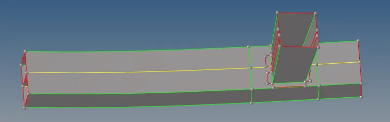
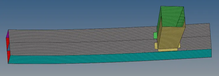
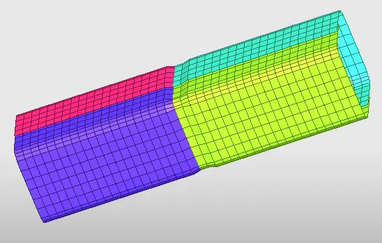
- Perform mesh using 2D -> Automesh -> select surface -> mesh size = 6 mm -> create. Repeat this process for all the remaining surface. Try to create quads if possible.
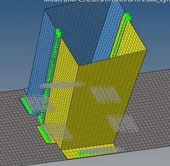
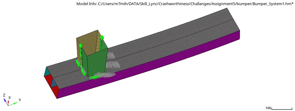
- Since the parts in the given geometry are separated, they need to be created using different means of connectors to represent the actual model. Here Spot -> weld and Area -> adhesive methods are used to represent the connections using limited nodes. The no of connectors can be increased as per requirement using the same procedure.
- 2D-> Connectors -> Spot -> Select nodes -> select components -> Type = Weld -> Create. 2D -> COnnectors -> area -> Adhesive -> select elements -> select components -> create.
Part II - Follow the instruction given below and run the simulation for a given specimen
Case 1 - Run the crash tube model as it is.
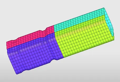
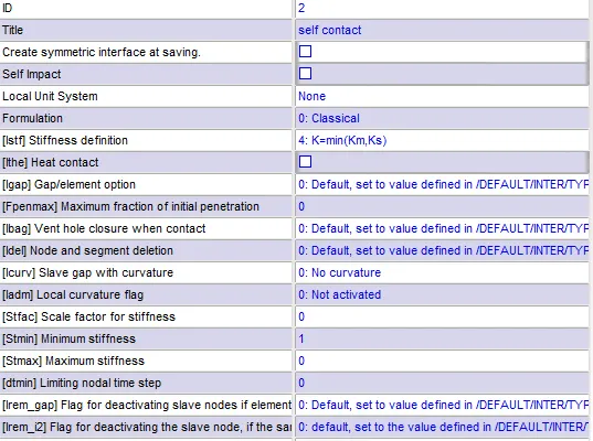
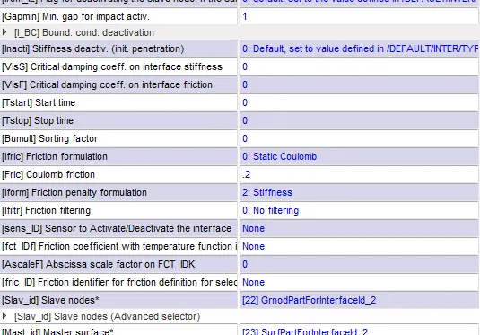
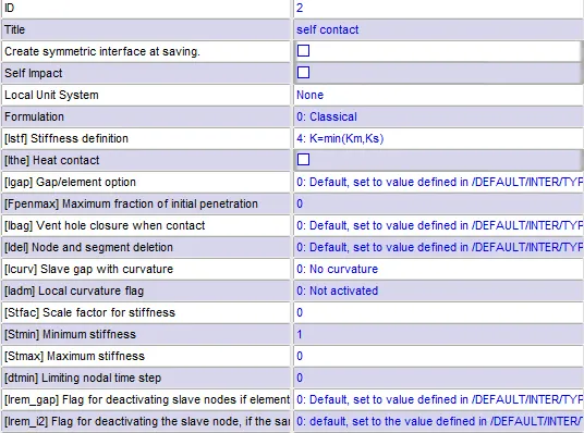
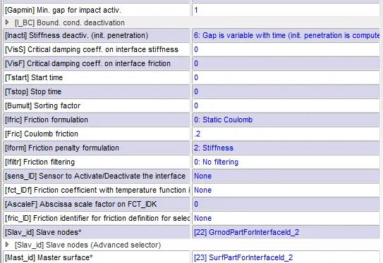
Here type 7 contact (node to the surface) is defined with default properties is used for the interface. The below image shows the contact card.
Type 7 - self contact
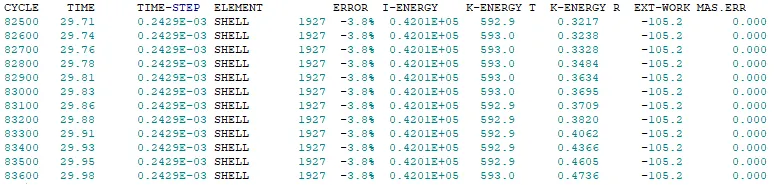
Results
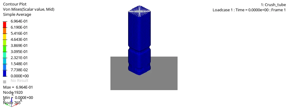
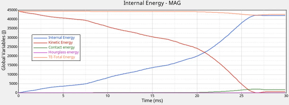
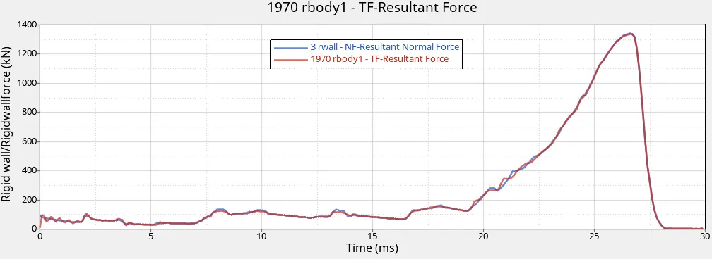
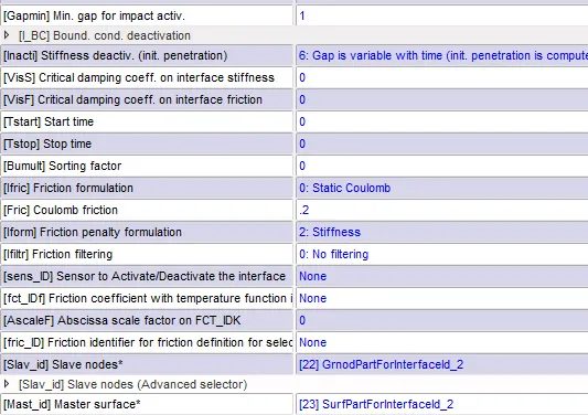
Case 2 - Change the Inacti=6 and run.
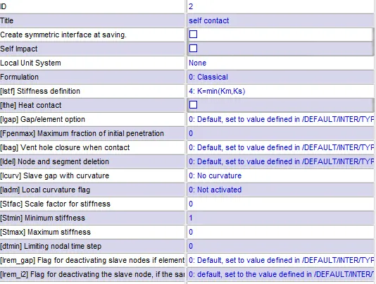
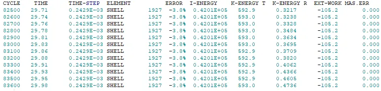
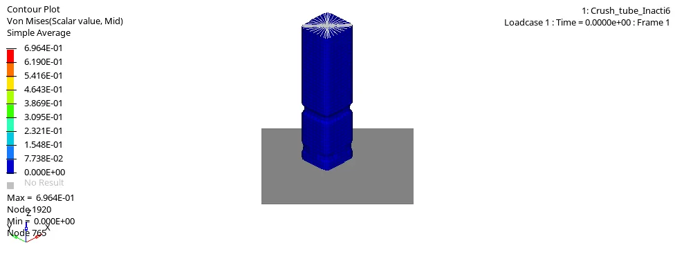
Inacti = 6 means that remove the initial penetration where possible. Else reduce it to 30 % of the defined gap to avoid stability issue.
Type 7 - self contact
Results
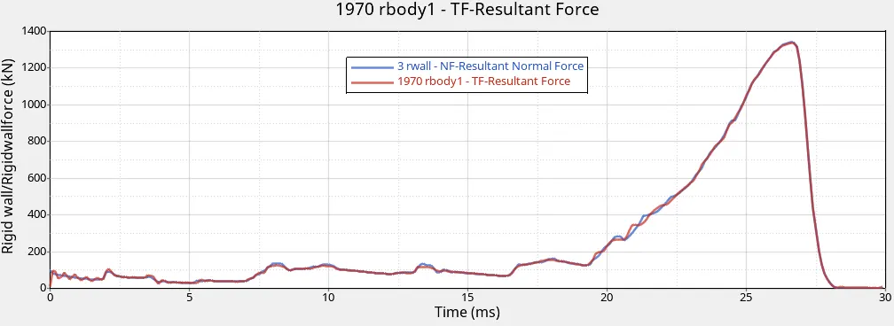
Case 3 - Create the type 11 contact and run.
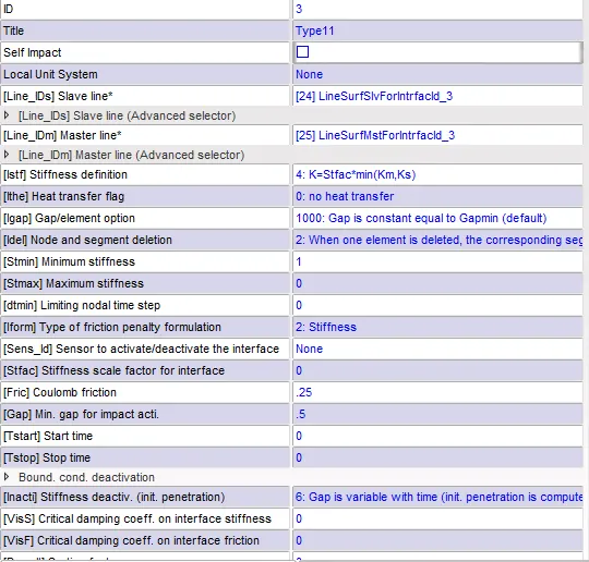
Type 7 contact is Node to surface contact. It cannot capture the effect of the edge of an element in slave penetrates the master segment and thus create some error in the form of deeper penetration and larger contact forces. To avoid this a new edge to edge contact TYPE 11 is defined to detect the edge penetration.
Type 7 - self contact
Type 11 - edge to edge
Results

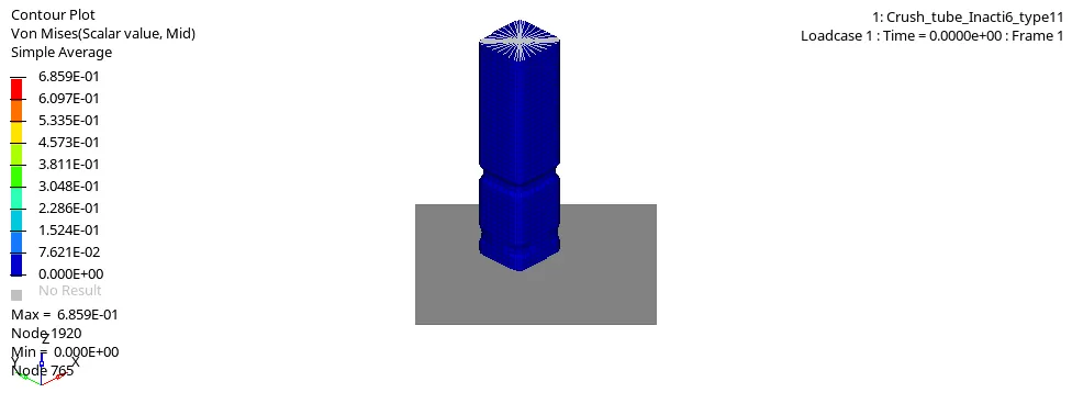
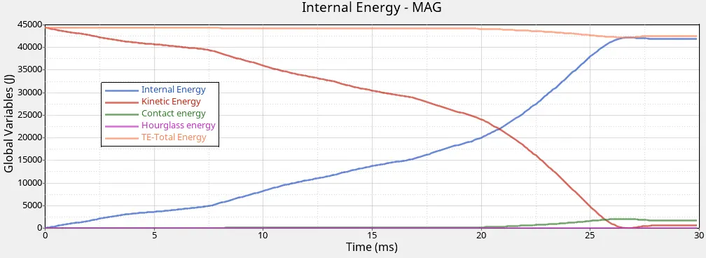
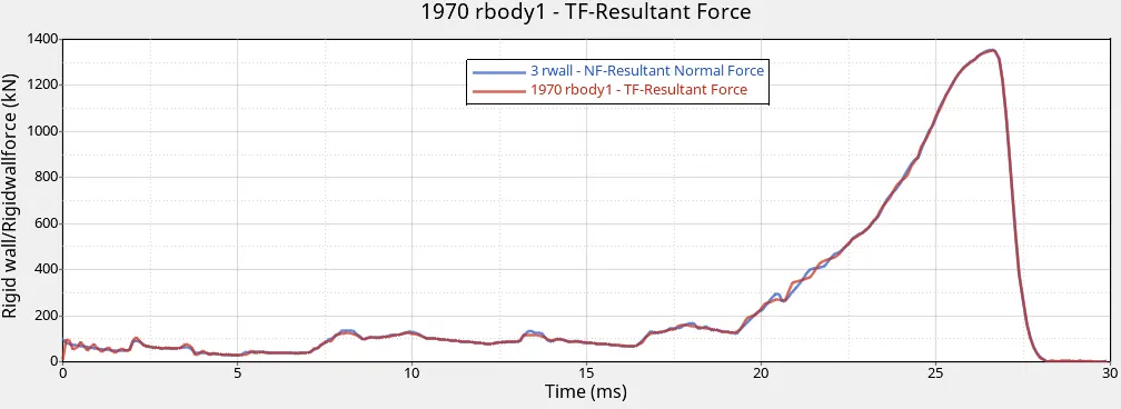
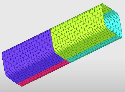
Case 4 - Remove both notches and remove boundary conditions on a rigid body node then run.
Type 7 contact for self contact
Type 11 for edge to edge
Results
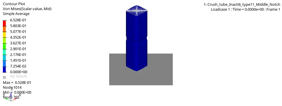
Case 5 - Create a new notch in the middle, select the whole section, and run.
Type 7 contact for self contact
Type 11 for edge to edge
Results

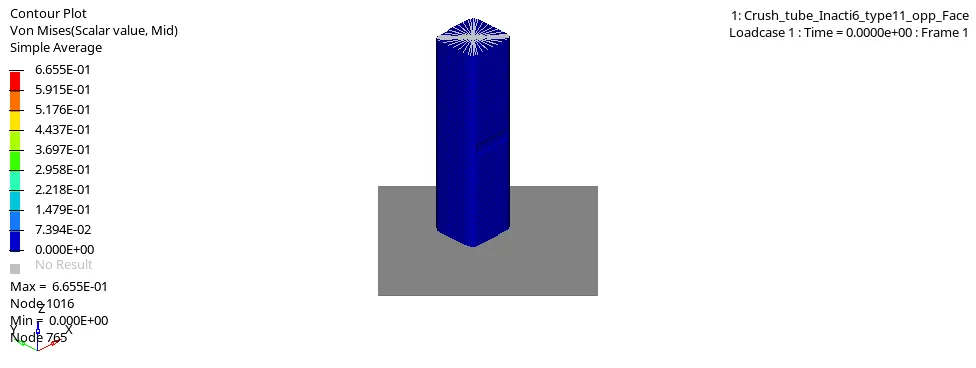
Case 6 - Create a new notch with nodes only from opposing 2 faces and run.
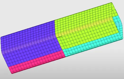
Type 7 contact for self contact
Type 11 for edge to edge
Results

OBSERVATIONS
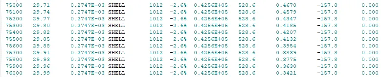
looking at the results of energy, force and simulation following observations were made
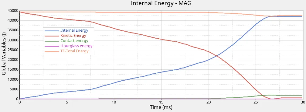
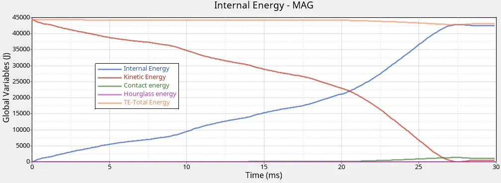
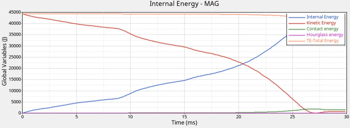
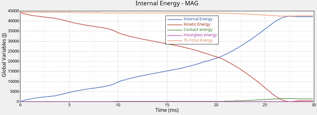
- Energy is conserved in all the cases discussed above and thus confirming that our simulation is correct.
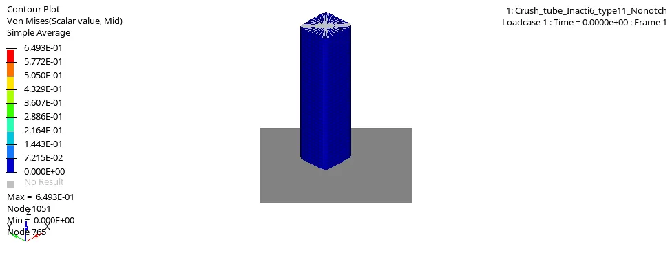
- The main difference between the models with notch and without notch is upon impact we see part not only crumbles from the point of impact but also starts bending from area around the notch. Whereas in specimen without notch, we see failure only commencing in the point of impact.
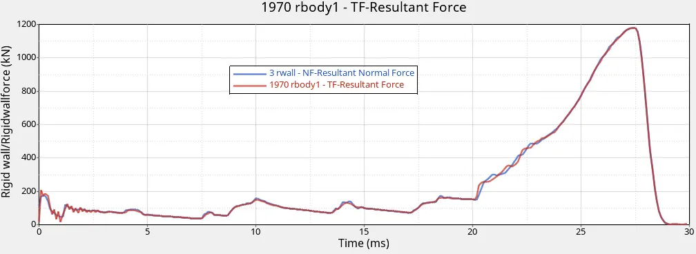
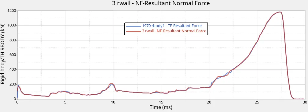
- Forces in specimen with notch are higher as compared to the specimen without notch or with only half notches. This results into higher stresses in the specimens with notch which can be confirmed from the maximum stress values.
- With introduction of notch the error in the energy also increased.
- Since this is a simple simulation setup, not much difference is observed in case 1 and case 2 (introduction of inacti =6). But ideally in complicated examples, this helps in reducing energy and mass errors in the simulation and thus improving the reliability of simulation.
- Hourglass energy in all the cases discussed above remain almost neglible which shows that there are no unwanted elemental behaviour. Also very small spikes are seen during the end of simulation when the crash tube is almost crushed into itself. This also can be rectified and removed with the use of finer mesh.