Study of contact mechanics setup in HyperCrash and HyperMesh using Bumper Assembly model
Objective: Study of different types of interface using HyperCrash and meshing of bumper assembly
Case 1: Run the crash tube model as it is.
Case 2: Change the Inacti=6 and run.
Case 3: Create the type 11 contact and run.
Case 4: Remove both notches and remove boundary condition on rigid body node then run.
Case 5: Create a new notch in the middle ,select the whole section and run.
Case 6: Create a new notch with nodes only from opposing 2 faces and run.
The above cases are to be compared on the basis of:
- Rigid wall forces, contact forces, internal energy, and Energy variation for all parts.
- Effect of notches on the simulation results
- Energy and mass errors.
Procedure:
1) Meshing of the bumper assembly:
Recognizing free and unconnected edges in the model:
Free and unconnected edges imply only one connection of the surface, and that is ideal for the edges at the end of the surfaces. However, presence of free edges anywhere else in the model represents improper connectivity. This results in inaccuracy of the FEM results.
Likewise, if there are penetrating surfaces present in the model, they can lead to overlapping nodes and elements which can again contirbute to the inaccurate nature of the results.
To detect such improper connectivity in the model, the topo mode is switched on. In the bumper assembly, upper crash box and lower crash box have these deformities in them.
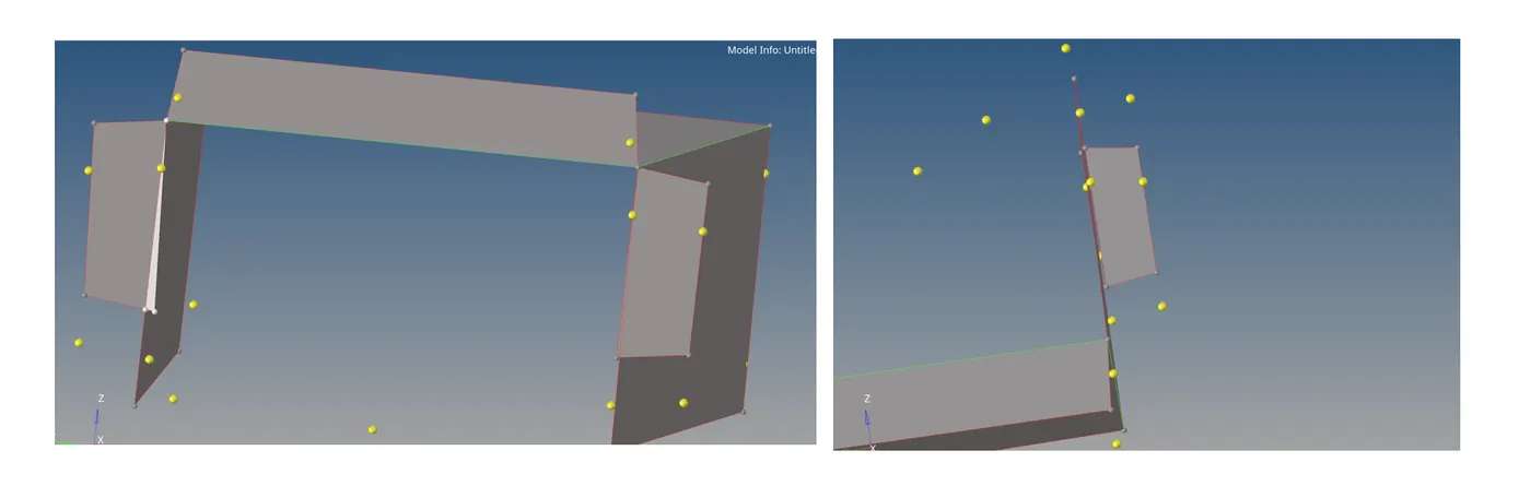
There are a couple of ways of dealing with such problems. Using the edges options and equivalencing those edges is one way to go about them.
For the free edges present in the model, extend option in the surface edit panel can also be used and option is used in this scenario.
Interssecting surfaces are trimmed using the trim using surfaces option in the surface edit panel. The unncessesary surfaces can then be deleted.

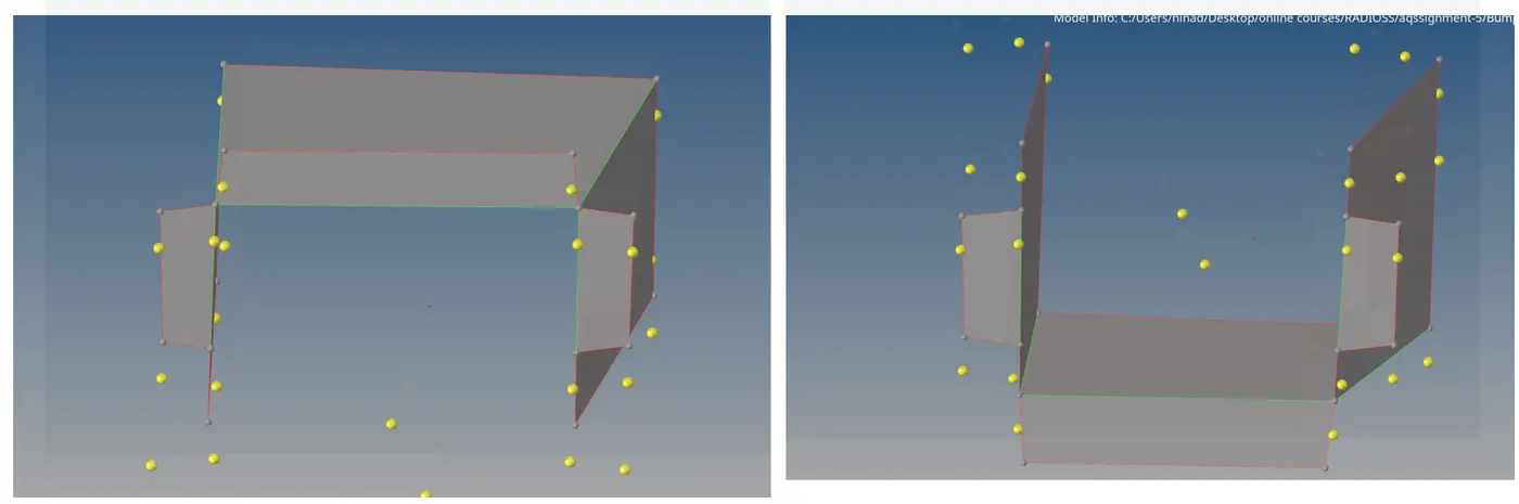
2D Meshing the assembly:
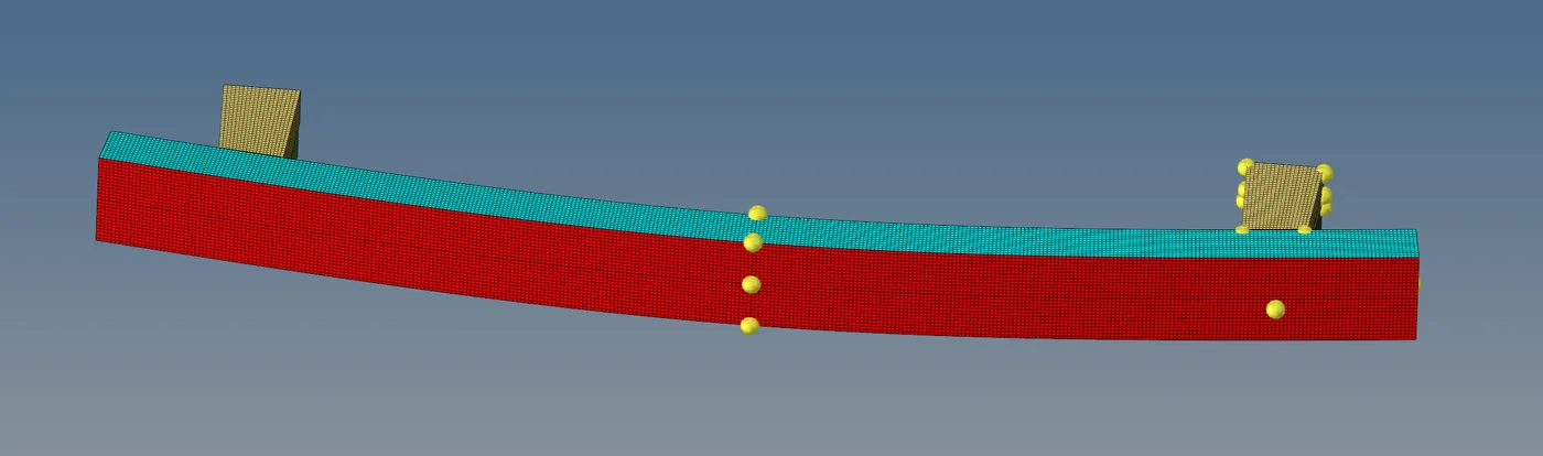
The assembly is then meshed using the 'Automesh' option in the 2D panel. The ideal size of the element is set to 6mm. The mesh is then mirrored/ reflected on the opposite side using the 'reflect' command in the hypermesh panel.

2) Interface/Contact modelling in HyperCrash:
HyperCrash for preprocessing: HyperCrash is a pre-processor for Radioss which is tailored to model crashworthiness. HyperCrash enables us to build a high quality crash model with a significant decrease in modelling time and errors, with a high level of homogenity. HyperCrash consists of the following tools:
Dummy Positioner, Seatbelt generator, Airbag folder and Seat deformer. HyperCrash also offers various quality checks, including most powerful intersection/penetration and fixing routine. It also allows users to model in a similar way to other solvers using databses of materials, properties, connectors, dummies, rigid wall/barriers etc.
Type 7 Contact: Node to Surface contact:
- It is a general purpose contact used to model most of the contact conditions
- A gap is an area around the node defined such that, while in contact, if the node from the slave penetrates the gap area; the counter forces are activated.
- It works on the logic of Impact penalty mehtod wherein the gap area and the behavior in the gap area is treated like a spring. These springs generate resisitive forces as counter-forces to the induced penetration from the slave nodes to the master
- The type 7 contact provides a cylindrical gap around the edges to take them into consideration while making the simulation more accurate.
- Certain parameters are used to define the type 7 contact:
Igap : The size of the gap is decided by the choice of this parameter
Gap_min : A default parameter to decide the minimum gap to activate the interface conditions
Inacti: Action to take in case of initial penetrations
Istf : Used to model the sitffness at the interface
Iform: Friction formulation
Stmin: Minimum stiffness to be used at the interface
Idel: Model the behavior of slave and master segments in case of element failures that are attached to the segments
The reason for defining the minimum stiffness and minimum gap are because of their effect on the timestep.
Deep penetrations lead to smaller timestep. This can effectively render the simulation unstable. Likewise, the timestep is inversely proportional to the stiffness. If the stiffness values are not kept in check, the timestep can exceed the range of minimum and maximum timestep that the user has decided for the simulation. This again can lead to inaccuracy and instability.
Limitations of type 7 contact is that it takes into account only the nodes on the slave side. Incase of circumstances where the surface of the slave comes into contact with the surface of the master, the interface routine is not activated and the results are inaccurate.
Type 11 Contact:
- It is characterized by edge-to-edge contact and is defined by slave and master segments.
- It works on penalty formulation in a similar manner to the type 7 contact.
- The parameters used to define the type 11 contact are same as that of type 7.
- It is used in conjuction to the type 7 contact to cover the nodes and edges of the slave. This overcomes the limitation of type 7 contact.
Energy error:
- Any system/simulation needs to maintain energy balance. The difference in the energy level of the system at the start and end of the simulation is called energy error. This value is computed in percentages.
It is computed using the following formula:
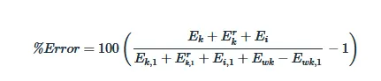
Where,
Ek">Ek:Translational kinetic energy at current time
Ekr">Erk :Rotational kinetic energy at current time
- If the error is negative, it means that some energy has been dissipated.
- This can also be due to the Hourglass energy which is not accounted for in this energy balance.
- In case of positive energy error, there is energy creation in the system.
- This is observed in case of QEPH elements since there is no Hourglass energy
The error should be negative and decreasing. Ideally it is better to have energy error between -15 to 5 %. It is better to have error closer to 0% since it represents a balance system. If the error keeps on increasing as the simulation proceeds, the error may soon grow to 99% and this might result in computational failure.
Importance of Inacti6:
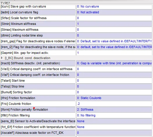
Inacti 6 sets the gap variable with time, and most importantly adjust initial penetrations in overlapping components. Penetrations are just the nodes of the slave element present inside the master surface gap before the start of the analysis.
Using it in conjuction with IGAP = 2, the variable gap is calculated as:
Igap = max{Gapmin, min[Fscale*(gs+gm), Gapmx]}
Where gm and gs are half the thickness of master and slave respectively.
In this, we hence find the Igap to be 2mm.
The components of the crush box are of different thicknesses . The parts closer to the rigid wall are of 2mm thickness whereas the parts away are of 3mm thickness. Due to overalapping components, the 3mm components will have intial penetrations pre-defined. To check for penetrations, a penetration check can be performed on the model.
Crash box:
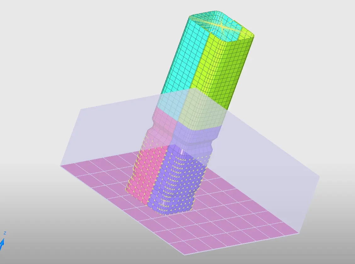
The file consist of 5 components, 2 property cards, 1 material card, a rigid wall, 1 interface. There is one material card defined by M2 plastic jhonson card with properties of a steel material.
Notch design: There are also notches present in the material. Notches help with the stress concentration. In this case, the crush box is a well designed crash absorber. The crash absorber needs to be able to a high amounts of energy during an accident so that minimal damage occurs to the passenger cabin. To commence buckling/crushing at a desired place in the model, the notches can be added to the model. These notches will then lead to stress concentration at those areas and maximum energy absorption can hence be seen in those areas.
With these concepts in mind, the cases are simulated.
Simulations and their results:
CASE 1: Run the model as it is.
The model was run with the defined parameters.
Once the simulation is completed, the output file 00001.out is opened in notepad to interpret energy errors in the system.

Number of cycles: 83,600
Energy error : -4.5%
Stress:
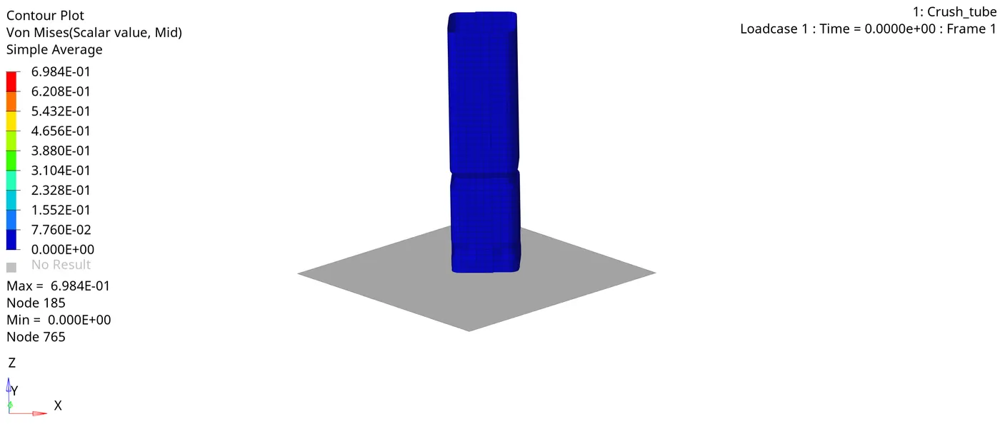
Time vs Rigid wall force:
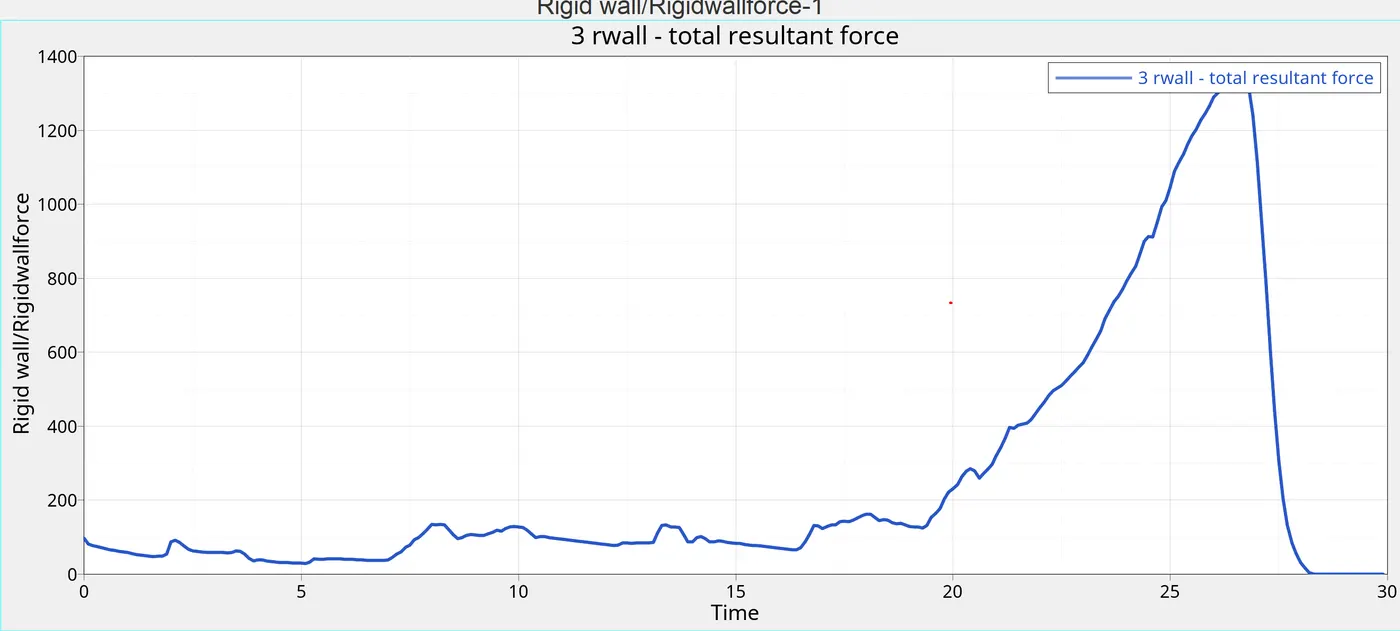
Time vs contact forces:
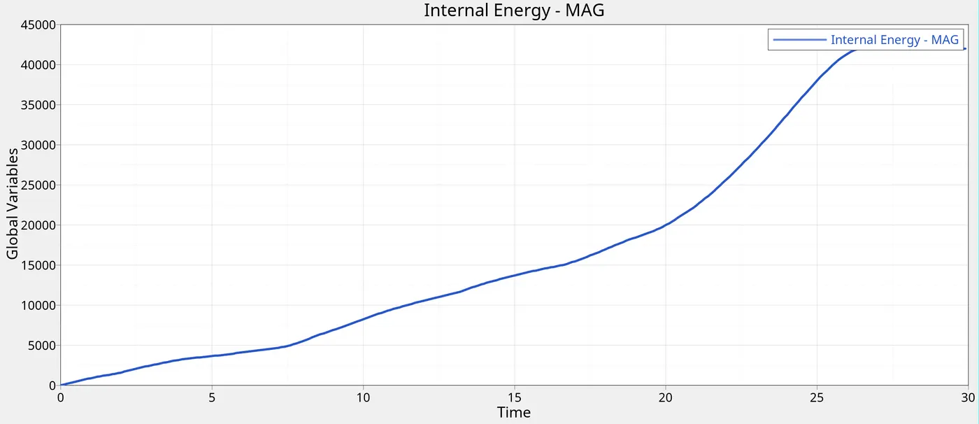
Time vs Internal Energy:
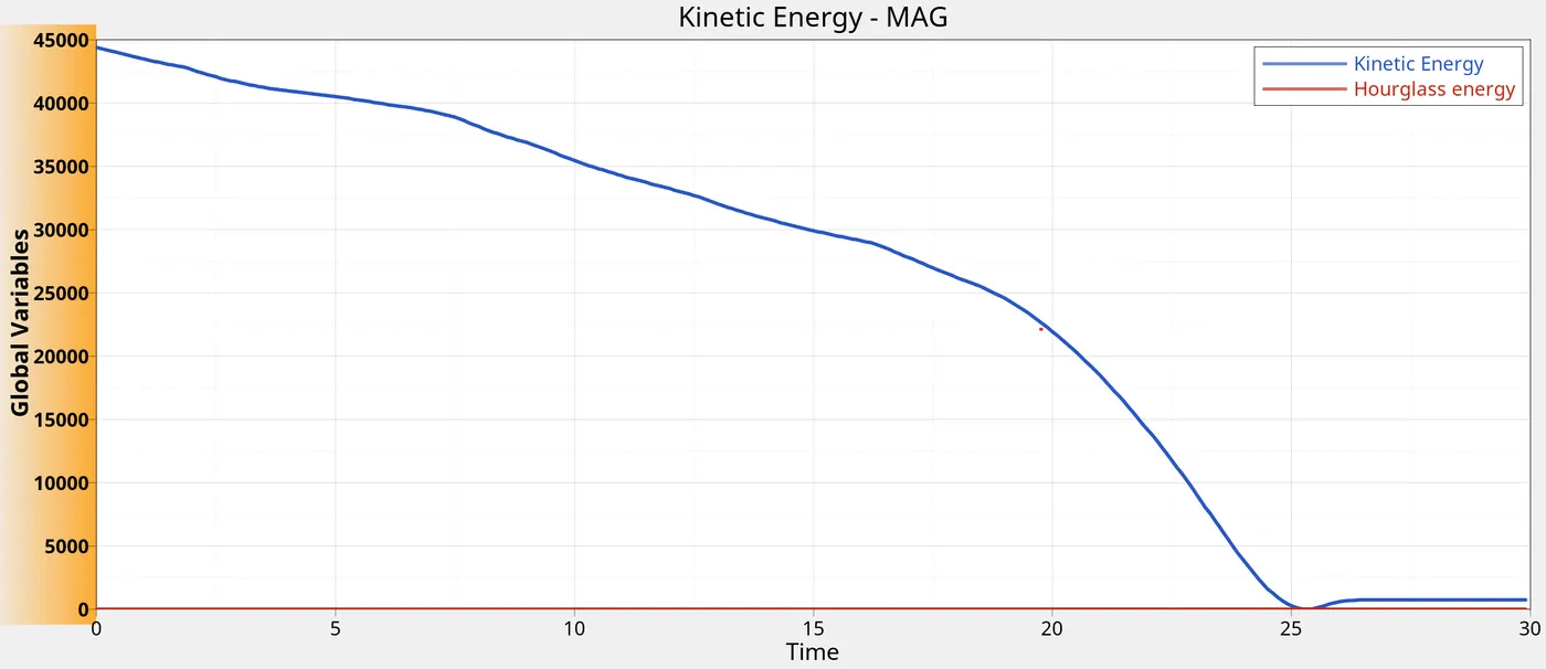
Time vs hourglass/kinetic energy:
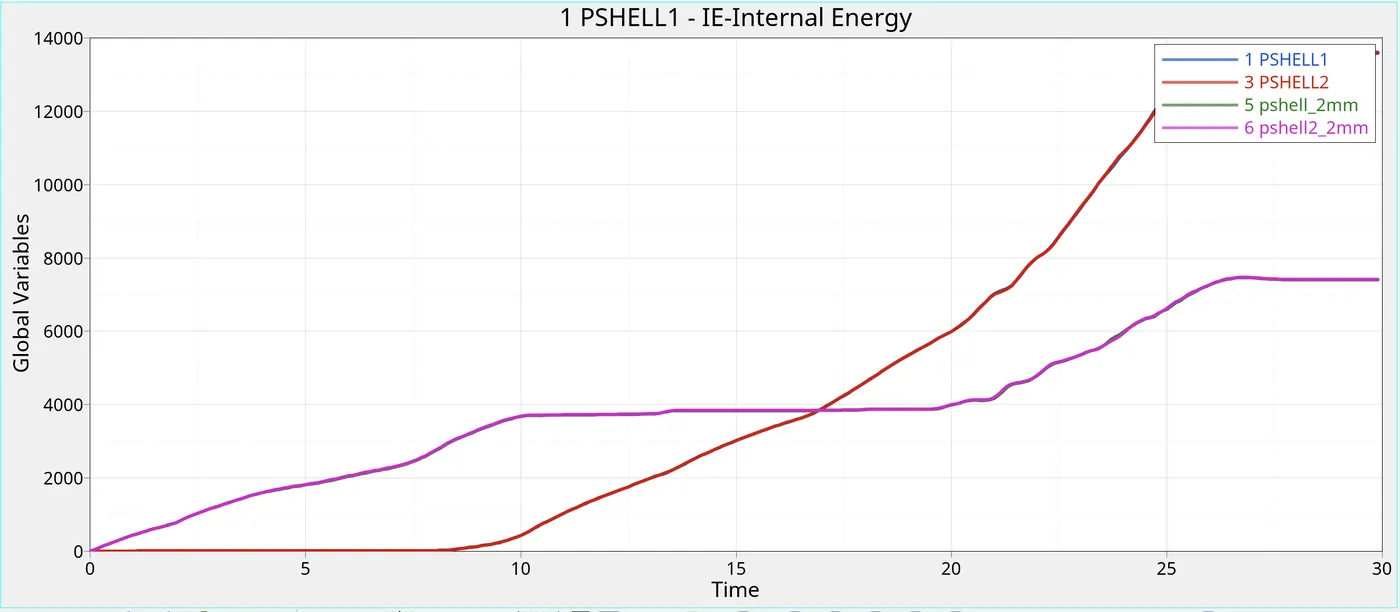
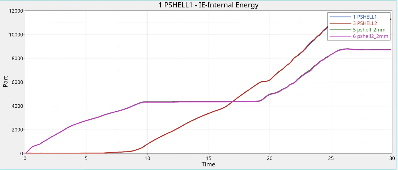
Time vs part internal energy:
Case 2: Type 7 contact with modified Inacti value modified
As explained above, to remove initial penetrations off the profile, the inacti value was changed to 6.
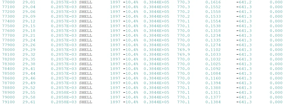
Energy error:

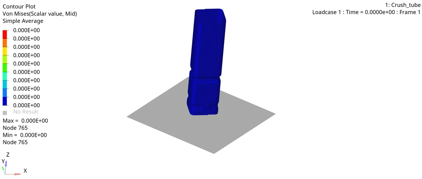
Von-Mises stress:
Time vs Rigid wall force:
Time vs contact energy:
Time vs Internal energy:
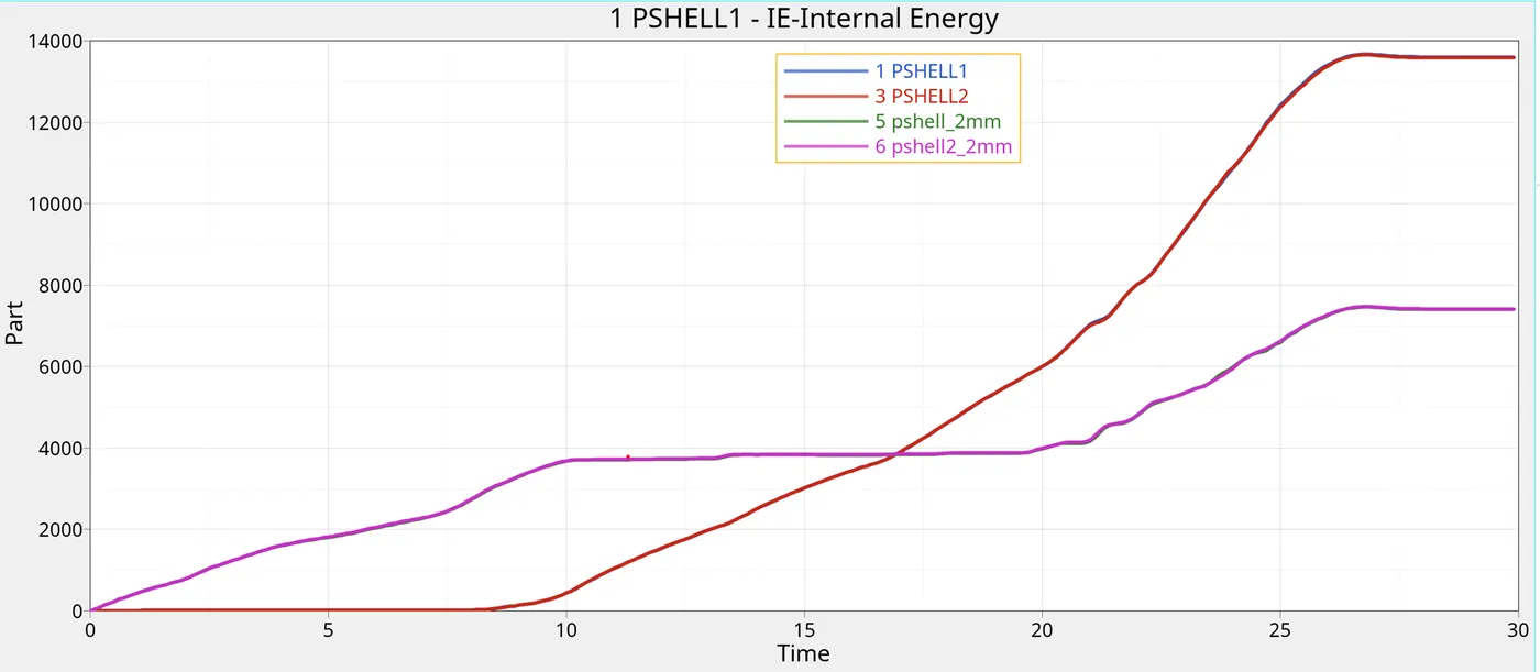
Time vs Part internal energy:
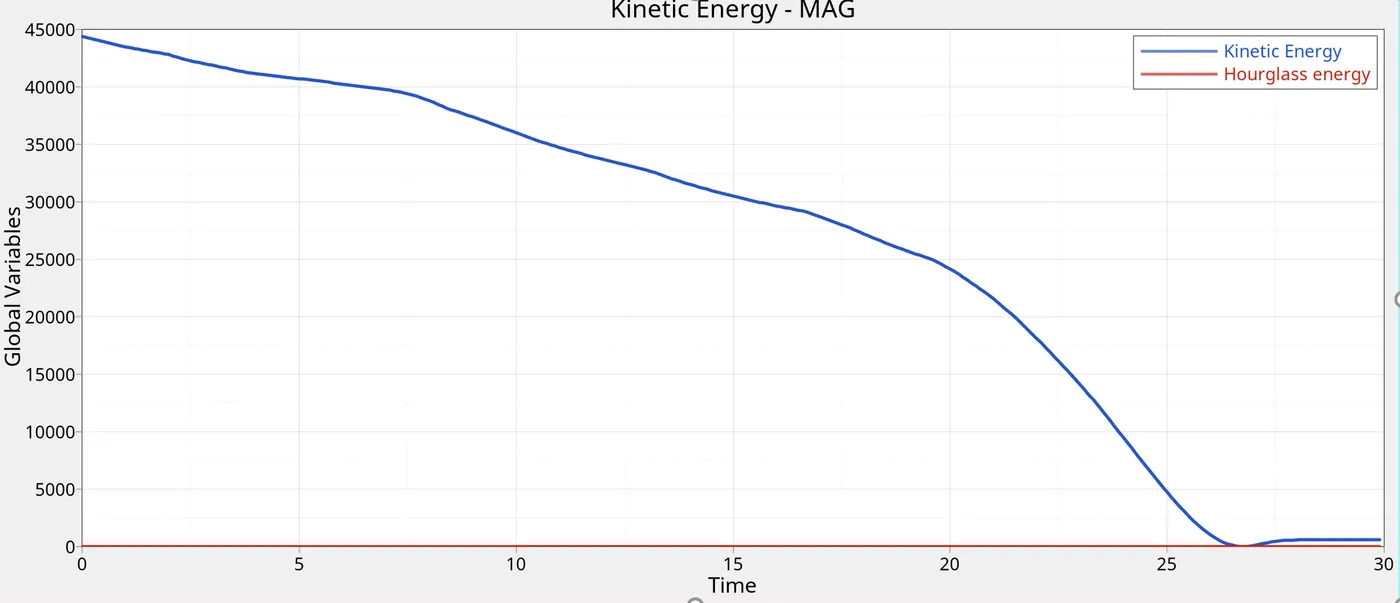
Time vs kinetic/hourglass energy:
Case 3: Type 7 + Type 11 contact with Inacti 6:
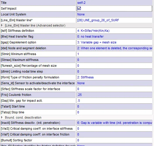
The file from the previous case is copied and type 11 contact is defined. In this case, recommended parameters are added to type 11.
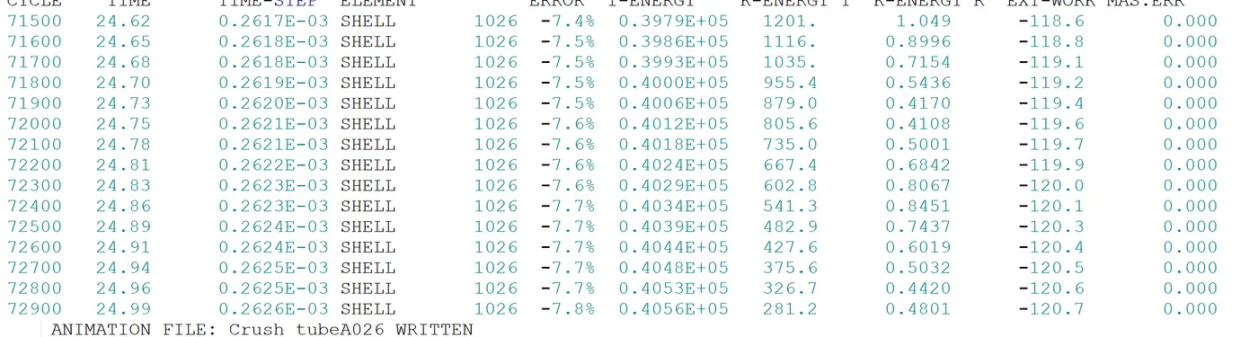
Energy error:
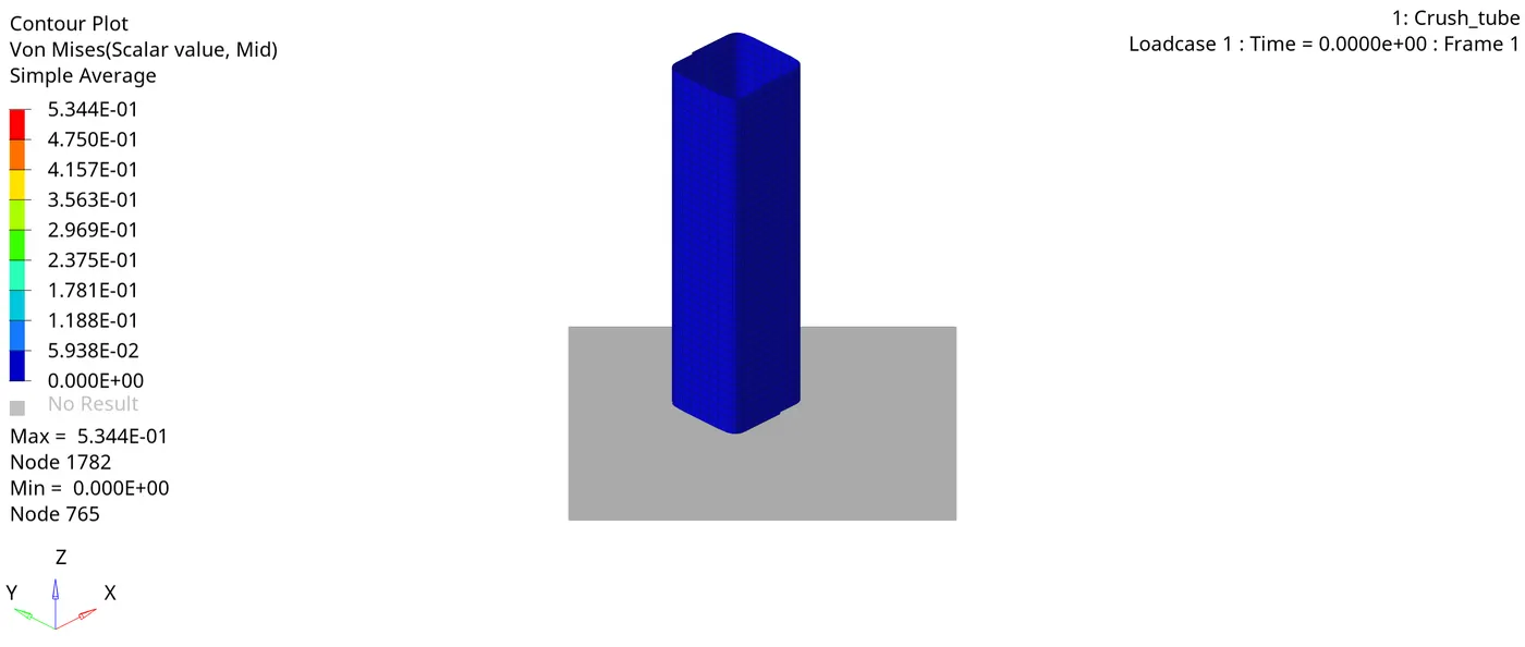
Von - Mises stress:
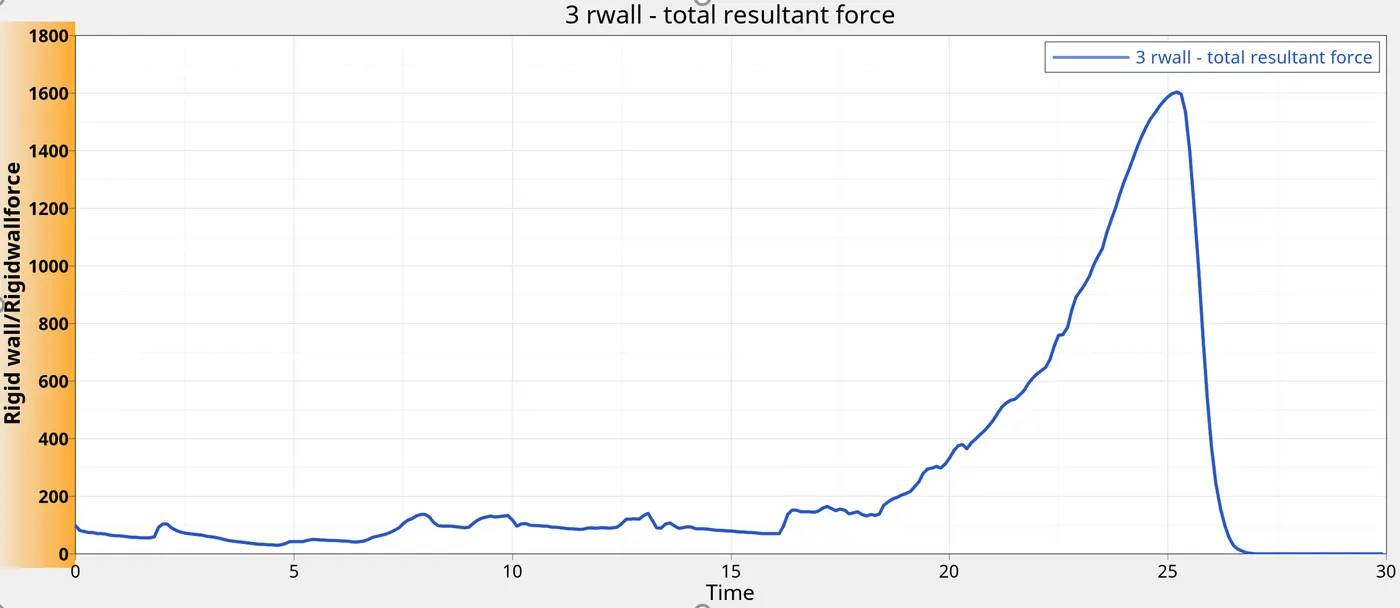
Time vs rigid wall forces:
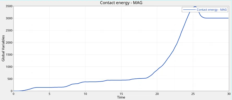
Time vs contact energy:
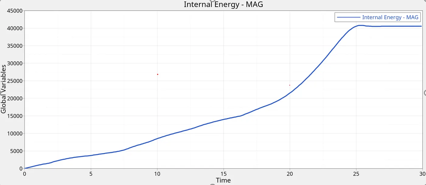
Time vs Internal energy: global
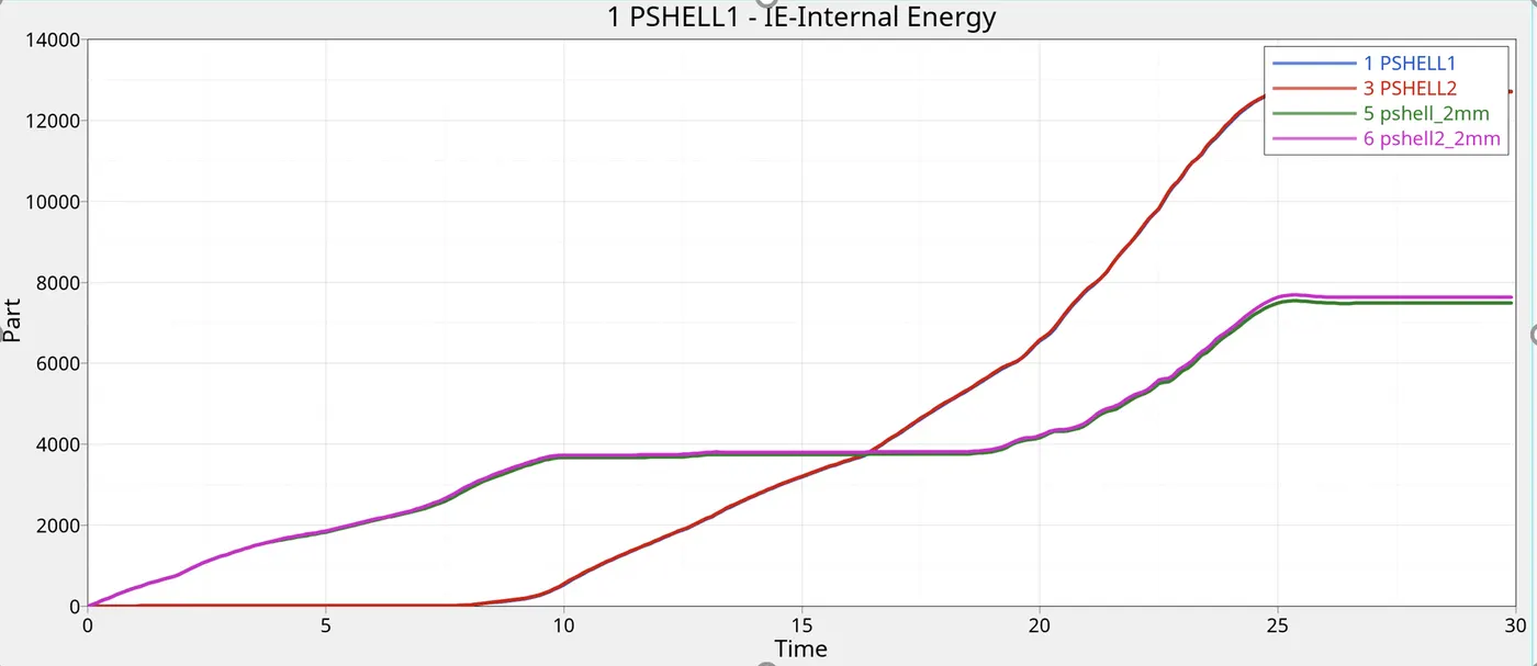
Time vs Internal energy parts:
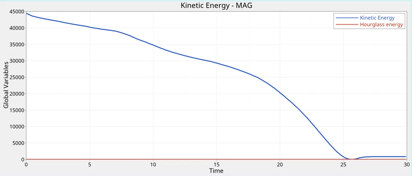
Time vs kinetic/hourglass energy:
Case 4:
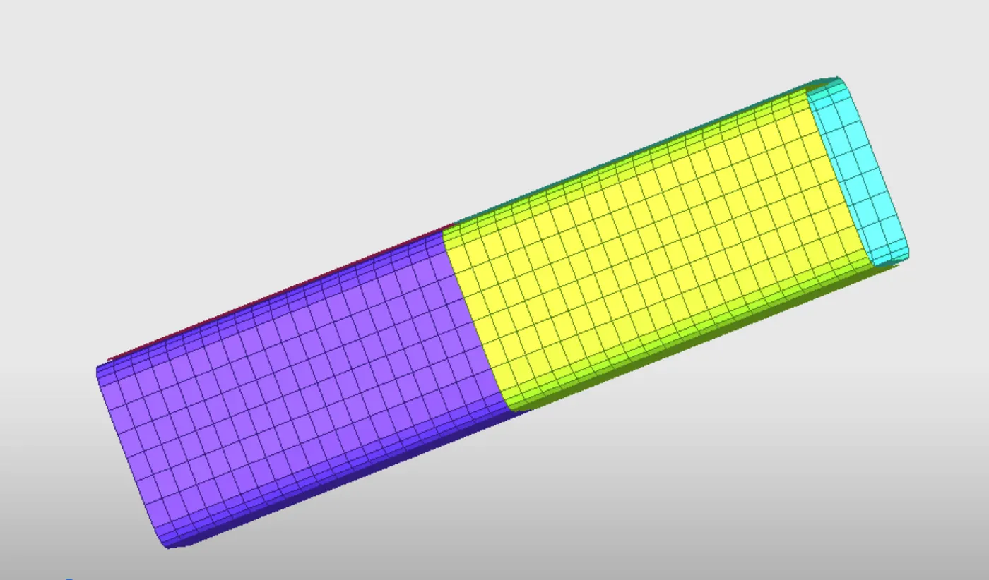
In this case, the notches are removed. Using the mesh editing in hypercrash, a notch free model is obtained.Rest of the conditions stay the same. The model is then run in Radioss
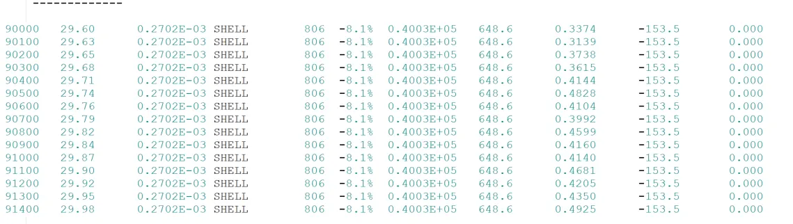
Maximum energy error is observed in this case.
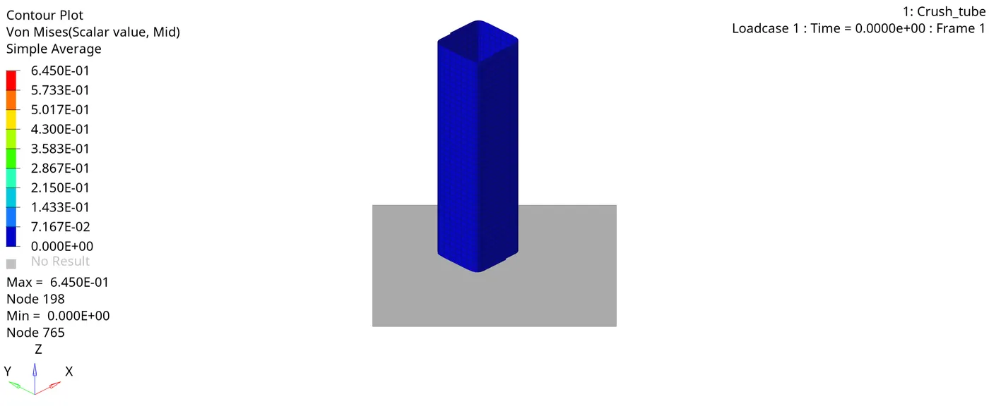
Von-mises stress:
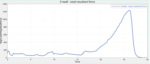
Time vs Rigid wall forces:
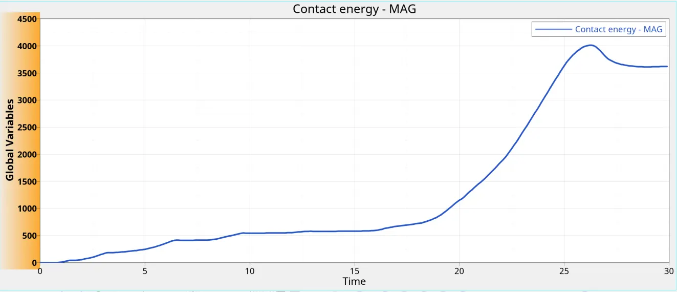
Time vs Contact forces:
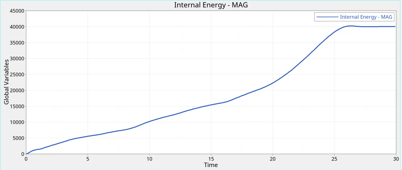
Time vs Internal Energy:
Time vs part internal energy:
Time vs Kinetic/hourglass energy:
Case 5:
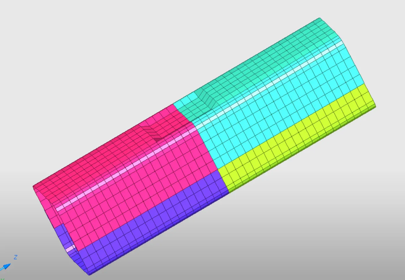
Notches are put up in one side of the model.
Energy error:
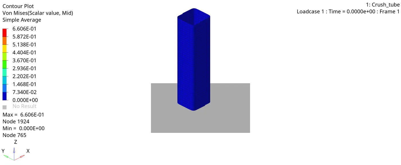
Von-Mises stress:
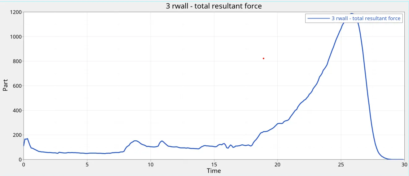
Time vs Rigid wall forces:
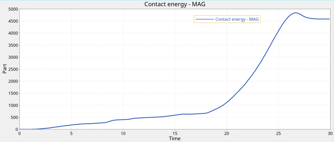
Time vs Contact forces:
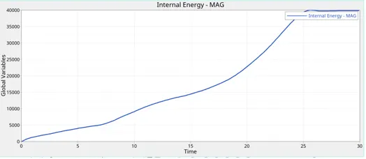
Time vs Internal Energy:
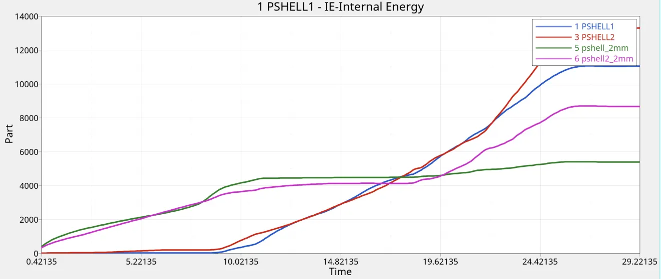
Time vs part internal energy:
Time vs Kinetic/hourglass energy:
Case 6:
For this case, Notches are added on both sides of the middle section:
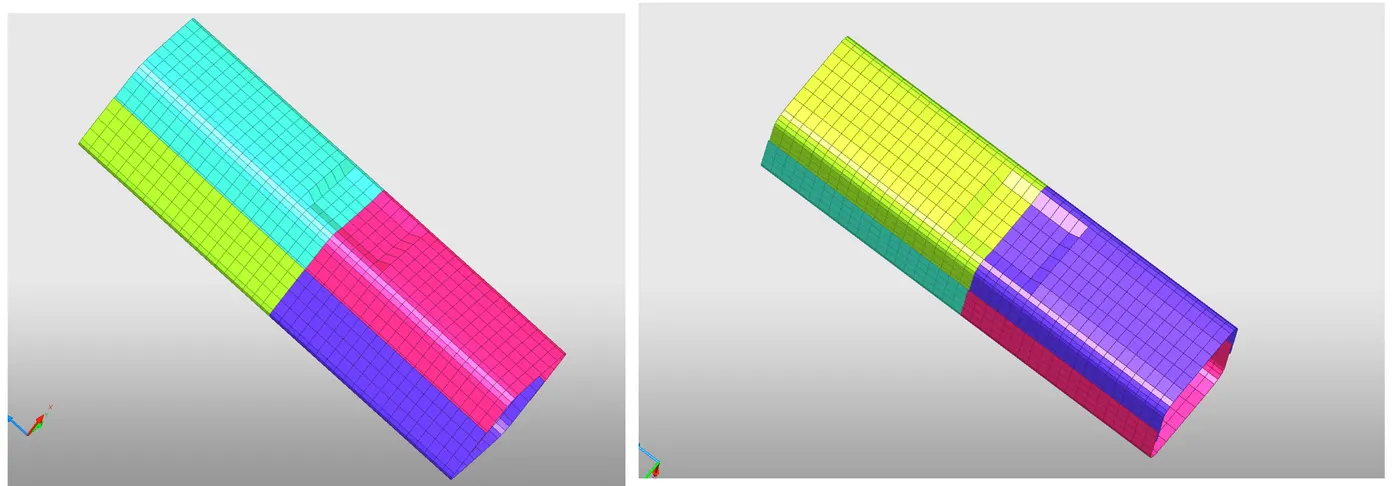
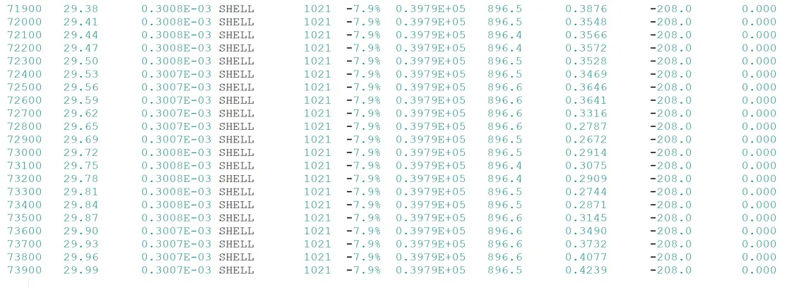
The energy error is observed to be highest as compared to rest of the cases:
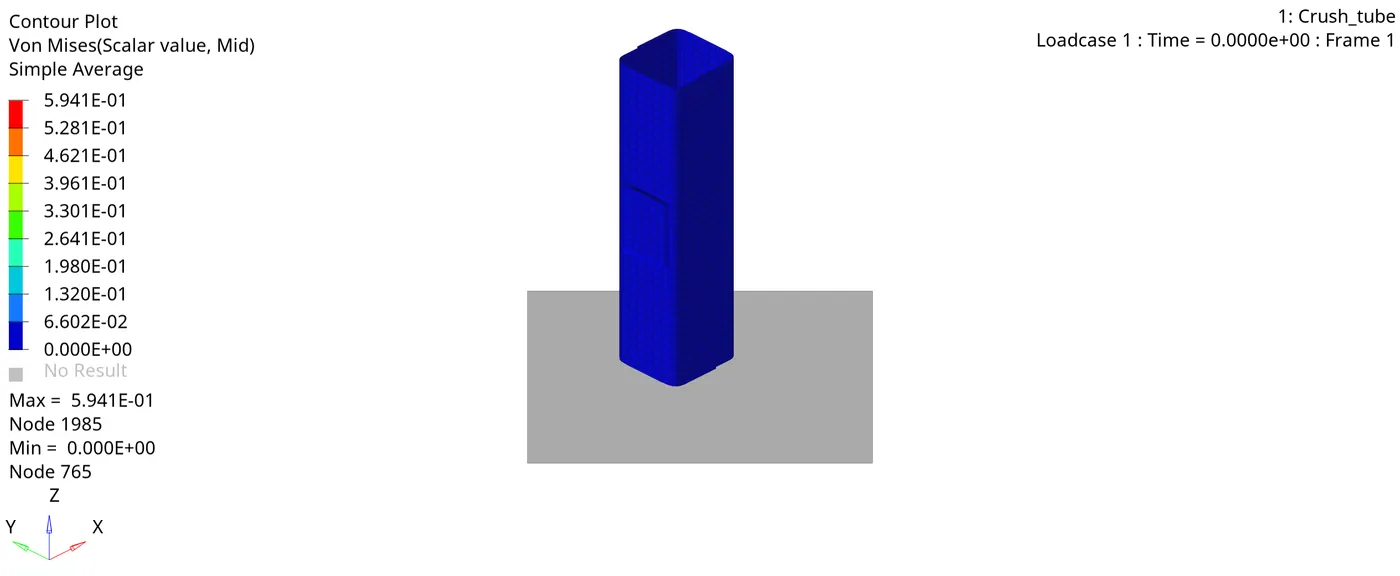
Von-Mises stress:
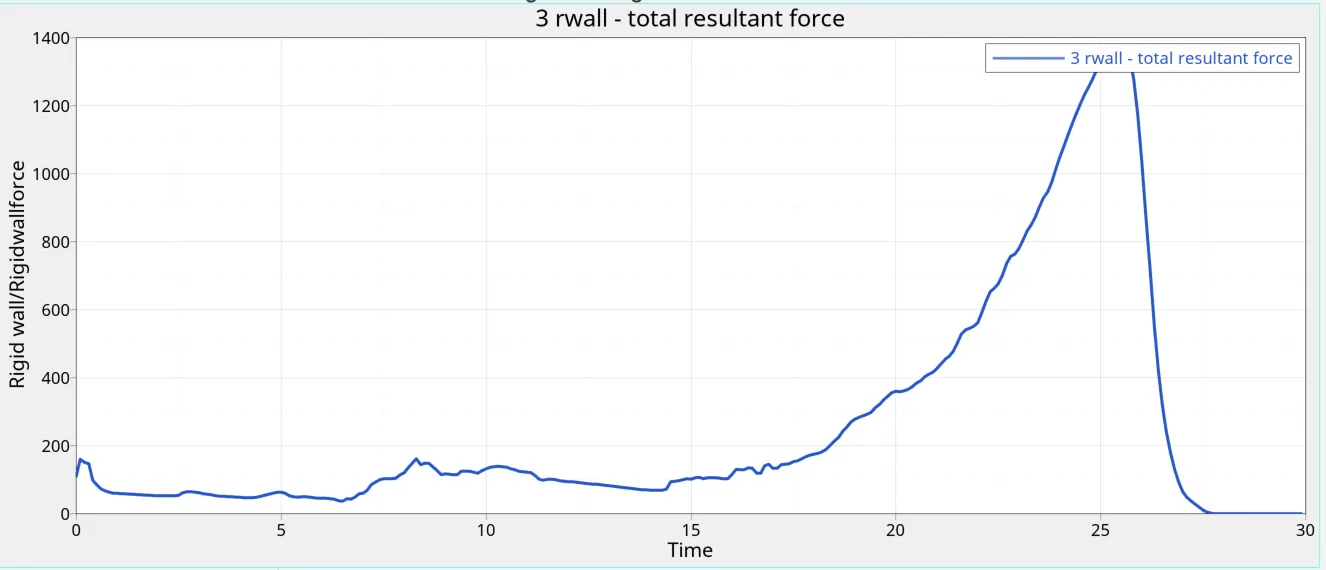
Time vs Rigid wall forces:
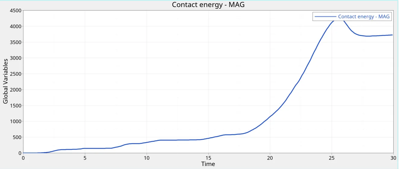
Time vs Contact forces:
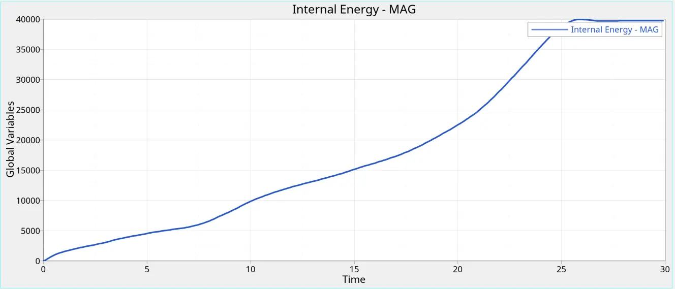
Time vs Internal Energy:
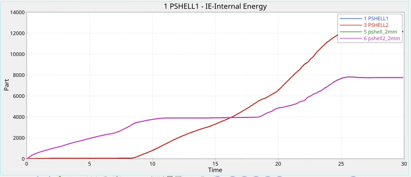
Time vs part internal energy:
Time vs Kinetic/hourglass energy:
Comparison report:
| Case | No of cycles | Energy Error | Mass Error | Simulation Time |
| Case 1 | 83600 | -3.8 | 0 | 91.35 |
| Case 2 | 83600 | -3.8 | 0 | 87.31 |
| Case 3 | 97494 | -4.7 | 0 | 129.3 |
| Case 4 | 91400 | -8.1 | 0 | 109.56 |
| Case 5 | 79100 | -10.4 | 0 | 114.65 |
| Case 6 | 73900 | -7.9 | 0 | 120.41 |
Inference:
The no of cycles for all observations varied. Energy error was acceptable for all simulations. Energy error was less in cases 5 and 6 where notches are present in the middle section.
Number of cycles directly affect the time needed for simulation. The number of cycles and subsequently time taken for simulation was found to be highest for CASE 3. This can be due to the complex setup of the problem since it involves both contacts and notches.
Von - Mises stress:
| Case | Case 1 | Case 2 | Case 3 |
| VM vs Time |
Max stress: 0.6964 GPa |
Max stress: 0.6334 Gpa |
Max stress: 0.6009 Gpa |
| Vm vs Time |
Max stress: 0.645 GPa |
Max stress: 0.606 Gpa |
Max stress: 0.594 GPa |
Inference: The position and the presensce of notch have an impact on the amount of stress generated. As discussed before, notches are placed so that they can take up maximum amount of stress. Notches at the middle result in lower stress values as compared to notches at the end. A complete rebound action can also be seen after the tube crashes into the rigid wall. The least sress is hence seen in Case 6.
Rigid wall forces:
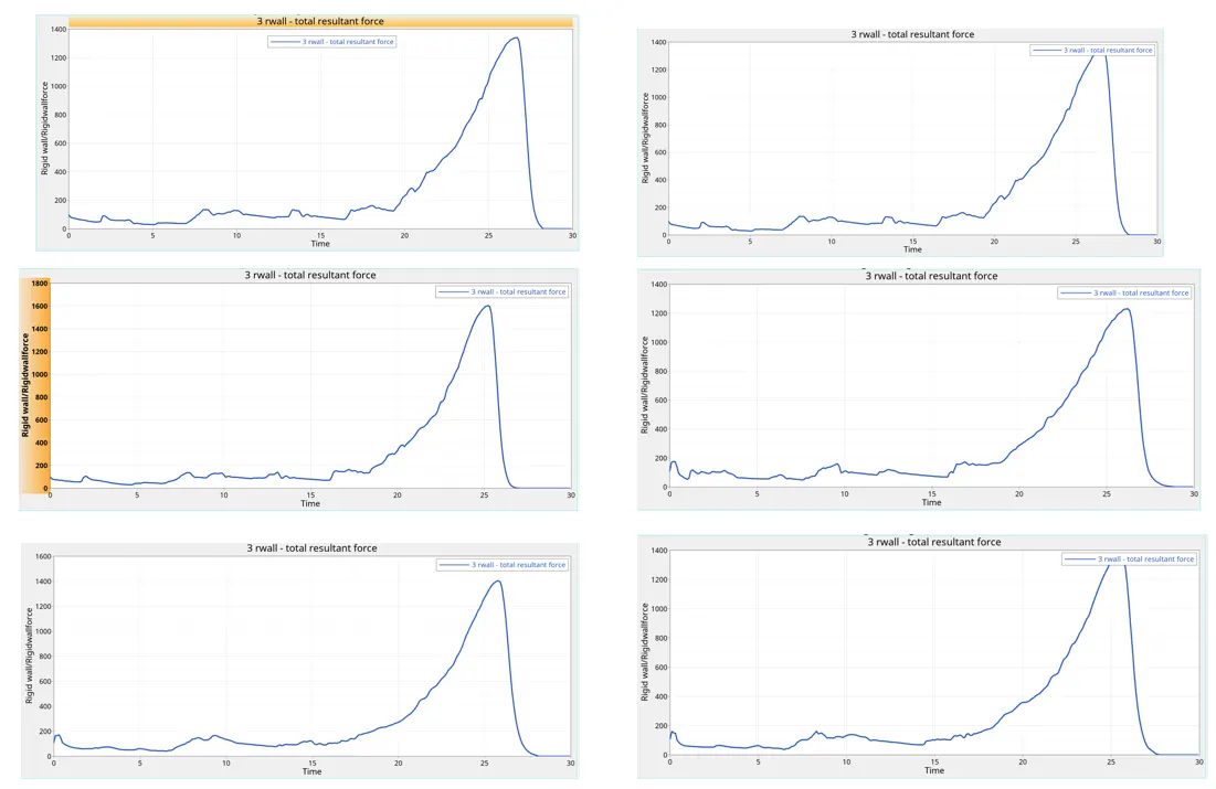
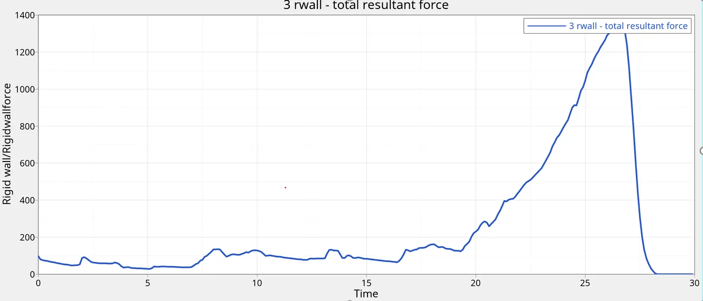
A similar profile of rigid wall forces was seen in all the cases. There is no change in the rigid wall forces due to change in Inacti value from 0 to 6. Rather, presence or absence of notches in the model affect the way in which the rigid wall reacts to the crash. Highest amount of forces in the rigid wall is seen in case 6 wherein notches are present in middle on both sides and the minimum is seen in case 4 which is free of notches.
It is also seen that the force keeps increasing, with a few decrements in-between. This can be due to few elements crashing while the crash is happening. A peak is observed in the model which indidcates that the whole tube has crashed. The rigid wall force then comes down to zero.
Contact Energy:
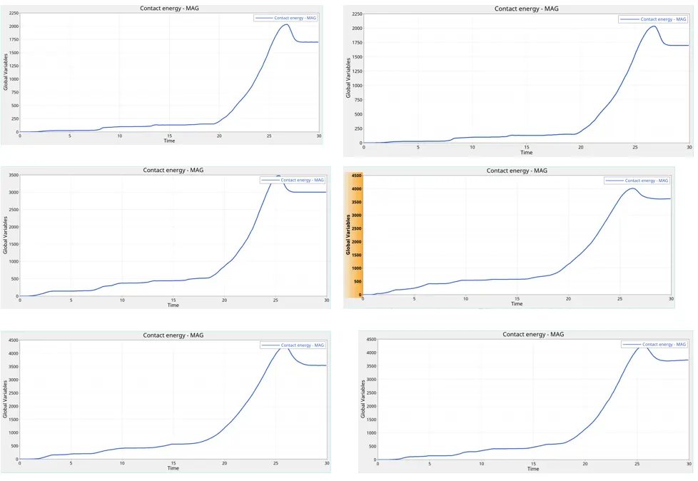
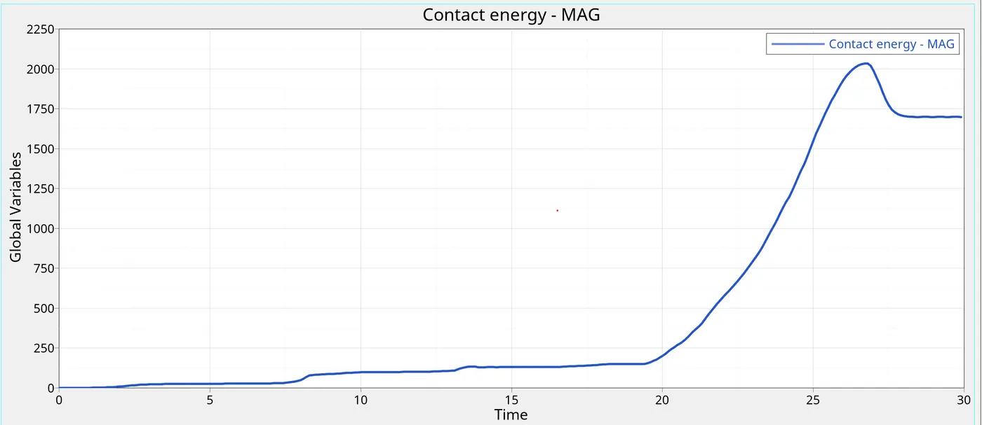
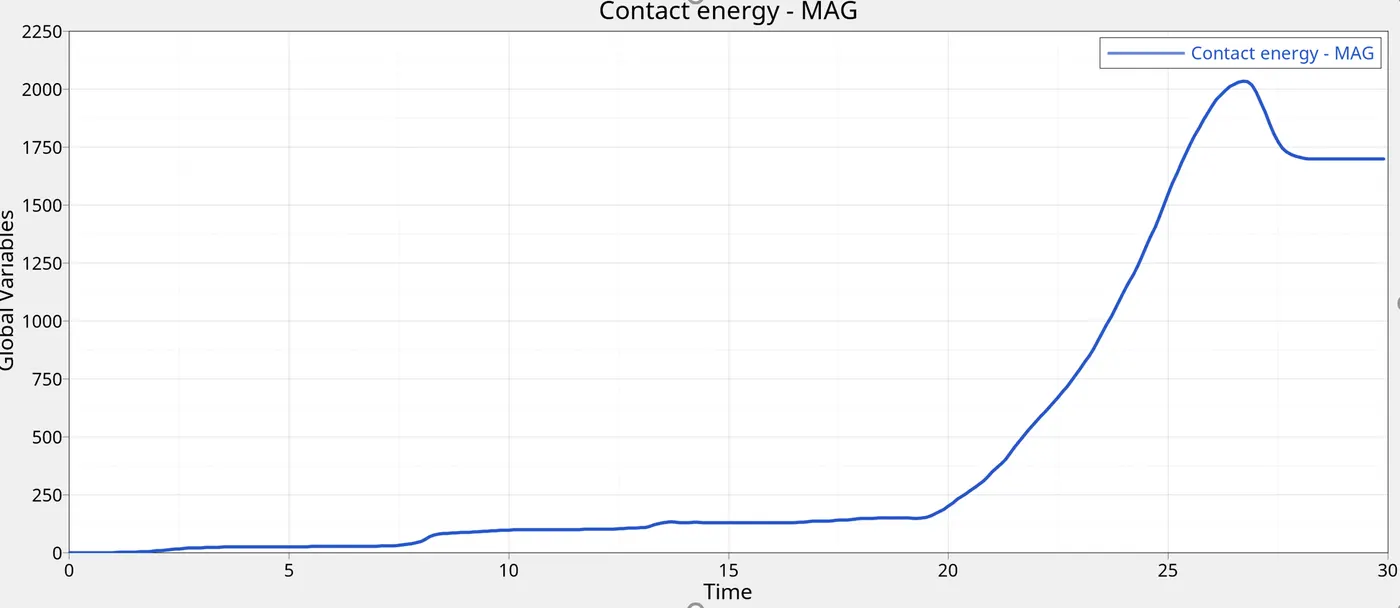
Inference: As seen above, all the cases show an increase in the contact energy till the tube crashes in the wall. A slight decrease follows after the tube has completely crashed. Maximum contact energy is seen in Case 1 & 2 while minimum contact wenergy is seen in Case 5.
Internal Energy: global and parts
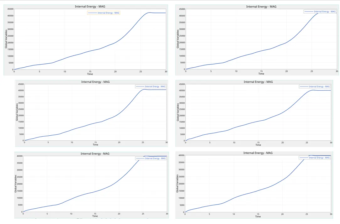
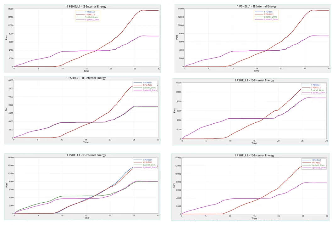
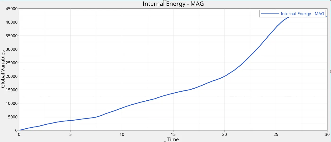
As the crash happens, most of the vehicle's kinetic energy is converted to potential energy. This is seen in all cases as the energies reach their maximum value towards the end of simulation. However, the time at which the system reaches its peak internal energy is different for all cases. When the notches are present in the model, they are the ones to absorb internal energy the most. So if the notches are present near the rigid-wall, the peak internal energy is reached early.
The part internal energy profile followed is very similar in all cases. The parts which come into contact with the rigid wall at a later stage havehigher internal energies as compared to parts which come into contact with the wall early in simulation. The models which have notches present experience the peak internal energy at an earlier stage.
Kinetic/ Hourglass energy profiles:
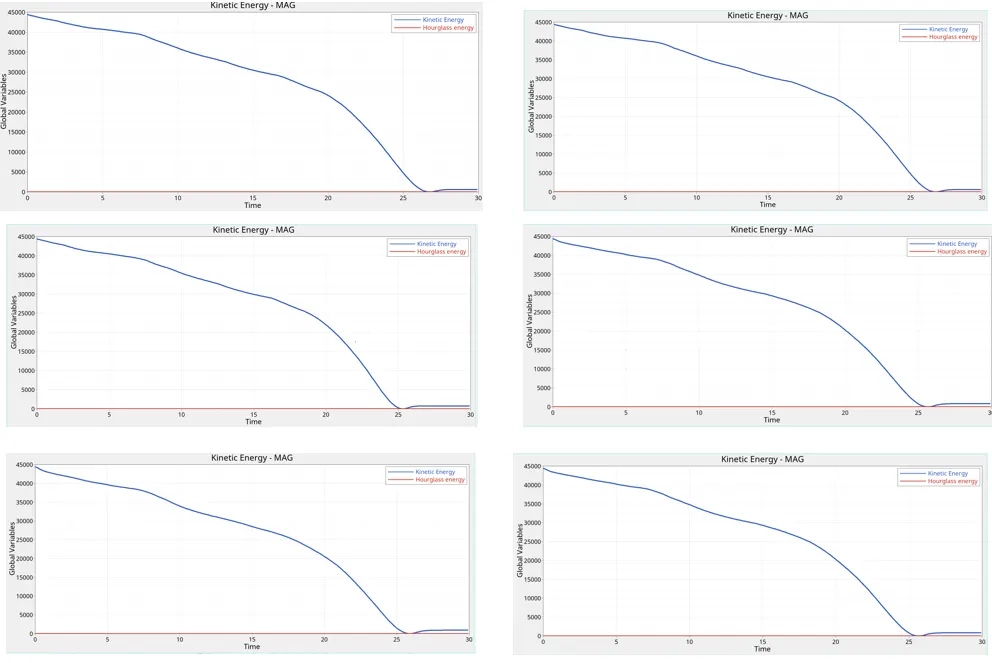
At the peak of the crash, when the velocity is effectively zero (and thus its kinetic energy is too), the car acts like a compressed spring, storing potential energy. On rebounding, the car regains a smaller amount of kinetic energy – this time travelling backwards. So the overall process is that kinetic energy becomes heat and spring potential energy, which results in heat, smaller kinetic energy. This small increase in kinetic energy is what we see at the end of the simulation.The hourglass energy is 0 for all cases.
Effect of notches on the simulation:
Notches are the first ones to get crushed in the simulation. The amount of energy absrobed by them, the effect they have on the rigid wall as their effect on the interfaces, are all depenedent on position of the notch in the model.
Conclusion:
Thus the bumper assembly has been meshed and the crash tube has been analyzed under various interface a and geometrical cicumstances.
Cases 1 and 2 have minimal result differences as there were no initial penetration present in the model at all. The files for the simulation are attached below.