Assignment 5 - crashing simulation with 6 different cases on Crash tube component
AIM :
- Perform 2D meshing operation on the given Bumper assembly component with 6mm element size
- To carryout crashing simulation with 6 different cases on Crash tube component and compare the result from case to case by plotting the graphs.
- Run the crash tube model as it is.
- Change the Inacti=6 and run.
- Create the type 11 contact and run.
- Remove both notches and remove boundary condition on rigid body node then run.
- Create a new notch in the middle ,select the whole section and run.
- Create a new notch with nodes only from opposing 2 faces and run.
Note:
- Plot RWALL forces ,contact forces,internal energy and Create TH/PART for all parts and compare results for all cases.
PROCEDURE :
- 2D meshing operation on the given Bumper assembly component with 6mm element size
Procedure for meshing the bumper assembly :
We will first import the model which is in (.hm) file format to the import solver deck then we will change it intO BYTOPO mode to cleanup the geometry incase if there are any geometrical errors.
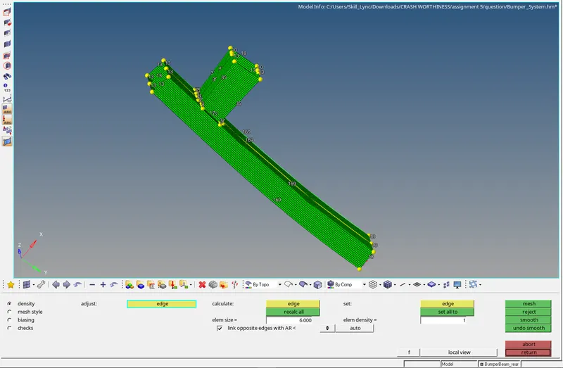
in the image below we can see that model is having surfaces which are supposed to be connnected. so we will make use of the surface edit panel because the extend tool is needed for us to extend the edge by selecting the line to the adjacemt surface so that they will be connected together.in brief we go to geometry-surface edit-extend-Extend over edges to surfaces and then we will select lines:to extend over and surfaces:to extend.
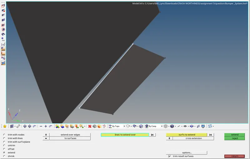
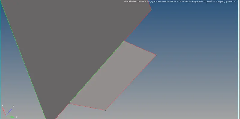
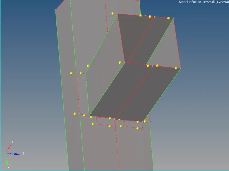
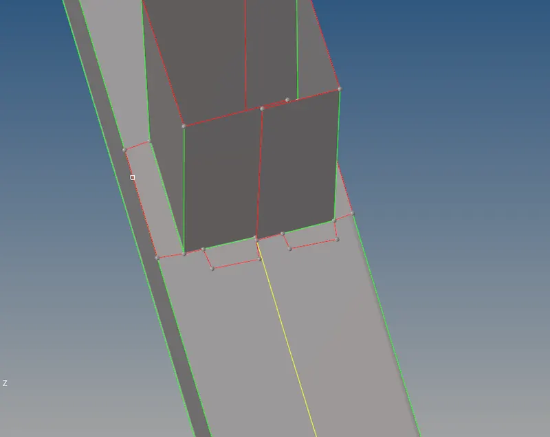
here we attcahed the surfaces with extend tool.these are some of the images that shows the difference before and after removing the surface erros.we also removed few nodes which are already present in the model with no use so we remove them by drag selecting all nodes at once and choose tempnodes option and cleared it.and then we toggled the surfaces which are having freeedges instead of T-junction edge.
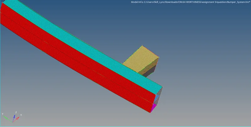
after clearing all the errors we will now proceed with meshing the component with 2D shell elements with 6mm size.go to automesh or by pressing F12 we will be redirected to meshing panel there we will select the surfacs to mesh and in it we can choose the typeof element and its size.we selected all surfaces at once to mesh instead of meshing one to one surface since we got a validable reason that the component is having all the rectangular flat surfaces by that we can say that the mesh will be fine structured if we deploy it in one go on all surfaces,even if there is any tria left it will be minimum quantity where we can manage them easily.here the below image shows the mesh that created on the cleanedup surface.here we maintained zero trias on the components with fine mesh and equal mesh density on both sides of the surface.
- Crashing simulation with 6 different cases on Crash tube component
- CASE 1 : Running the model as it is without any modification to the properties
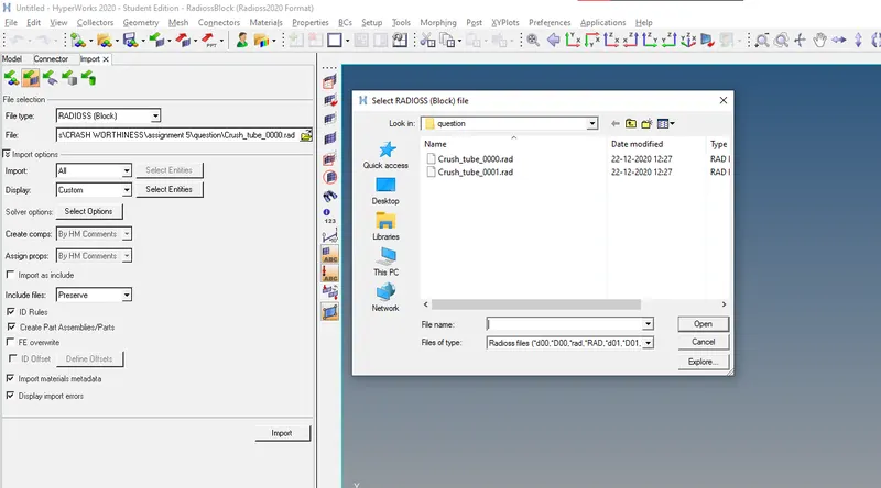
The first step is to import it in radioss(BLOCK) file type and choose the starter input file i.e.,
" Crash_tube_0000.rad " in the folder where we have downladed the model.After clicking on inort option the modle will be imported in graphic workspace.
To import the model click on IMPORT MODEL option or we can just cleck on file menu and there we can find IMPORT SOLVER DECK button to enable the import tab.then after selecting the import tab we will change the file type as RADIOSS and we select the input starter file in the tab just below the file type section.
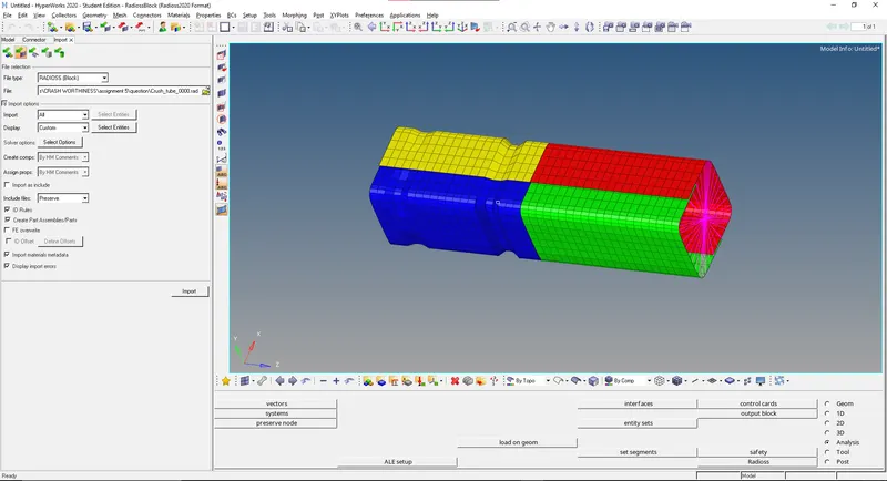
its quite commom sometimes after importing the model it shows up in wireframe by default which we can convert it to shaded mode by using the various mode buttons given under the workspace.
the below image shows the imported crash tube model ,now what all we have to do is go to Analysis-radioss in the radioss tool section we will place the copied inpiut file in a new folder for CASE 1 then proceed with a click on RADIOSS button to run the simulation.
In this case of simulation the model is ran with the default values without making any changes.Type 7 Contact Interface is defined.Interface TYPE7 is a multi-usage impact interface, modeling contact between a master surface and a group of slave nodes. It is also possible to consider heat transfer and heat friction.
All limitations that were encountered with interfaces TYPE3, TYPE4 and TYPE5 are solved with this interface:
- A node can at the same time be a slave and a master node.
- Each slave node can impact each master segment; except if it is connected to this segment.
- A node can impact on more than one segment.
- A node can impact on the two sides, on the edges and on the corners of each segments.
- It is a fast search algorithm without limitations.
The main limitations of this interface are:
- Time step is reduced in case of high impact speed or contacts with small gap.
- It does not work properly if used with a rigid body at high impact speed or rigid body with small gap.
as this is already having QEPH formulation the hourglass formation is zero and the energy error shows acceptable range.
To Run the Simulation we will Go to Analysis then Select the Location where the animated file we want to save then clicked on Radioss so that the Simulation will be carried out and the result is shown below:
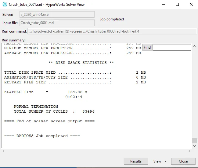
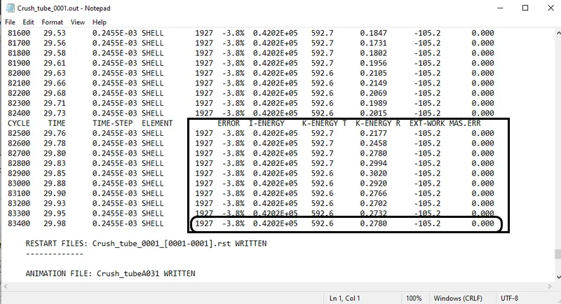
from the data we observed from the outputfile is that the maximum Energy Error Occured is 3.8% and mass Error is Zero.
Displacement :
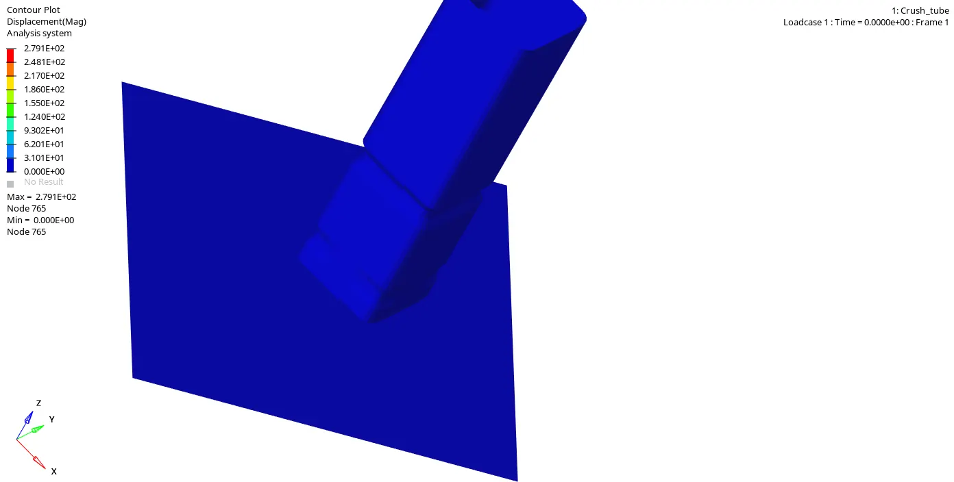
The displacement of the element are calculated. The lower part is not so much displaced because it is fixed and the upper part is displaced so ruoghly because of the rbody force is from the top.
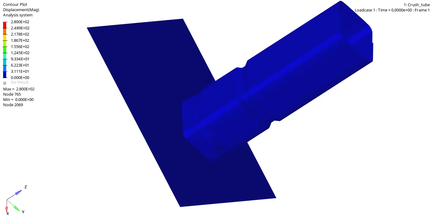
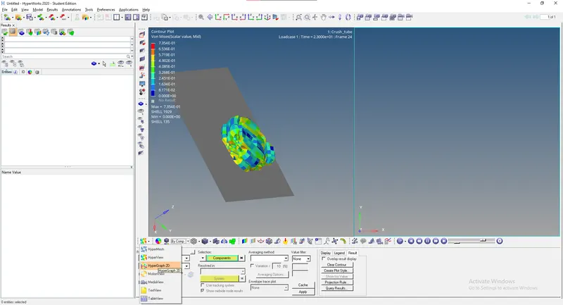
from the result we obtained by observing the animation of the model is that the node of ID 2009 which displaced to maximum of 2.800E+02
Von Mises Stress :
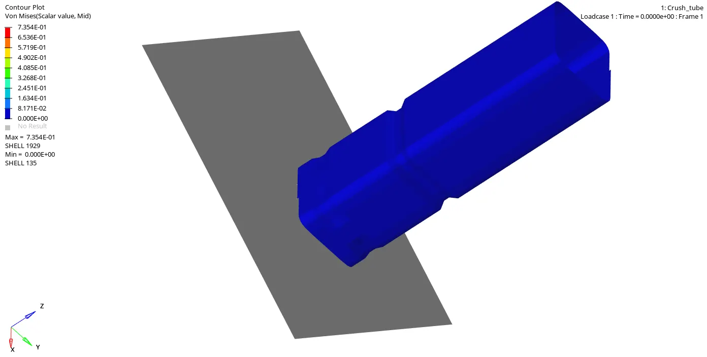
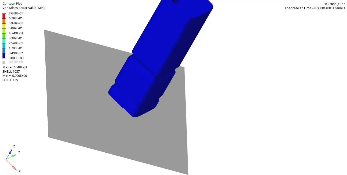
Maximum von Mises Stress is 7.354E-01
To plot the required graphs we will load TO1 file obtained from simulation in HyperGraph 2D.
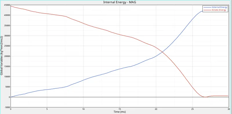
Graph plot : Internal and kinetic energy vs Time
from the above graph kinetic energy is high before the simulation starts because of the rbody force and it gradually decreases with increase in the internal energy of the system.This means the energy is converted into other form of energy(kinetic to internal) and this makes the total energy of the system to remain constant straight line. Before the last time step the total energy decreases with the small increase in the kinetic energy. This is because the retracts the penetration of the slave node into the master segment.
internal and the kinetic energies of the parts that created through the time history for the parts is plotted. In that the internal energies increases with the rapid reduction in the kinetic energy of the system.
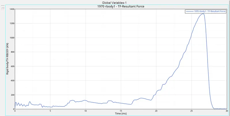
Graph plot : Resultant force vs Time
- CASE 2 : Change the Inacti=6 and run.
The same procedure is followed for this case too. The only change is the change in the initial penetration of the slave node into the master segment.
INITIAL PENETRATION:
This condition can cause locking situation leading to computation failure. So the initial penetrations should be removed from the model suing hypermesh and hypercrash.
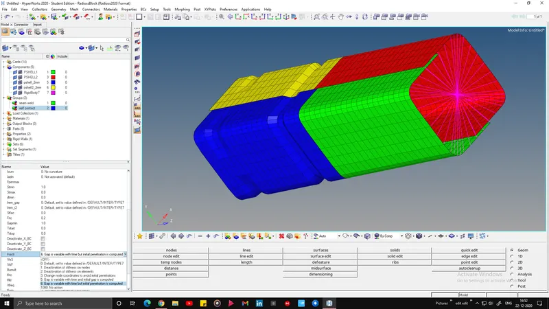
Penetrations result if the slave node is closer to the master segment than the calculated gap. Then the initial repulsive forces gives some error in the energy balance due to the contacts. To prevent this Inacti tool is used.
Inacti:
This option is having five variable types and eacha nd every variable is having a own characteristics.The inacti=0,5 and 6 are commonly used variable inputs.
In the previous case the Inacti=0 is used. The main advantage of the Inacti=6 is it add some extra scale to the initial penetration gap(gap p_o=+5%).The results for this case is saved in the local directory path file and energy differences are plotted.
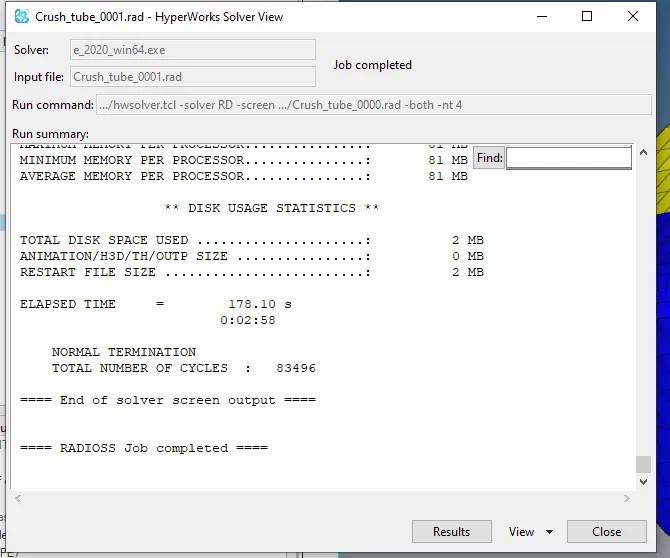
after assigning all the required data we will continue with simulation by clicking on RADIOSS button in analysis tab.we will make a seperatevfolder for each simulation type.the belowimage shows the simulation time that took for this case
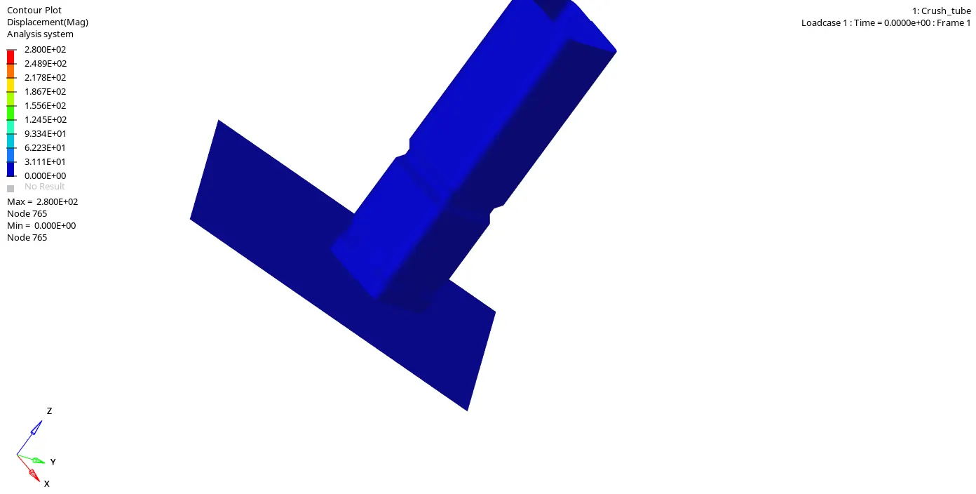
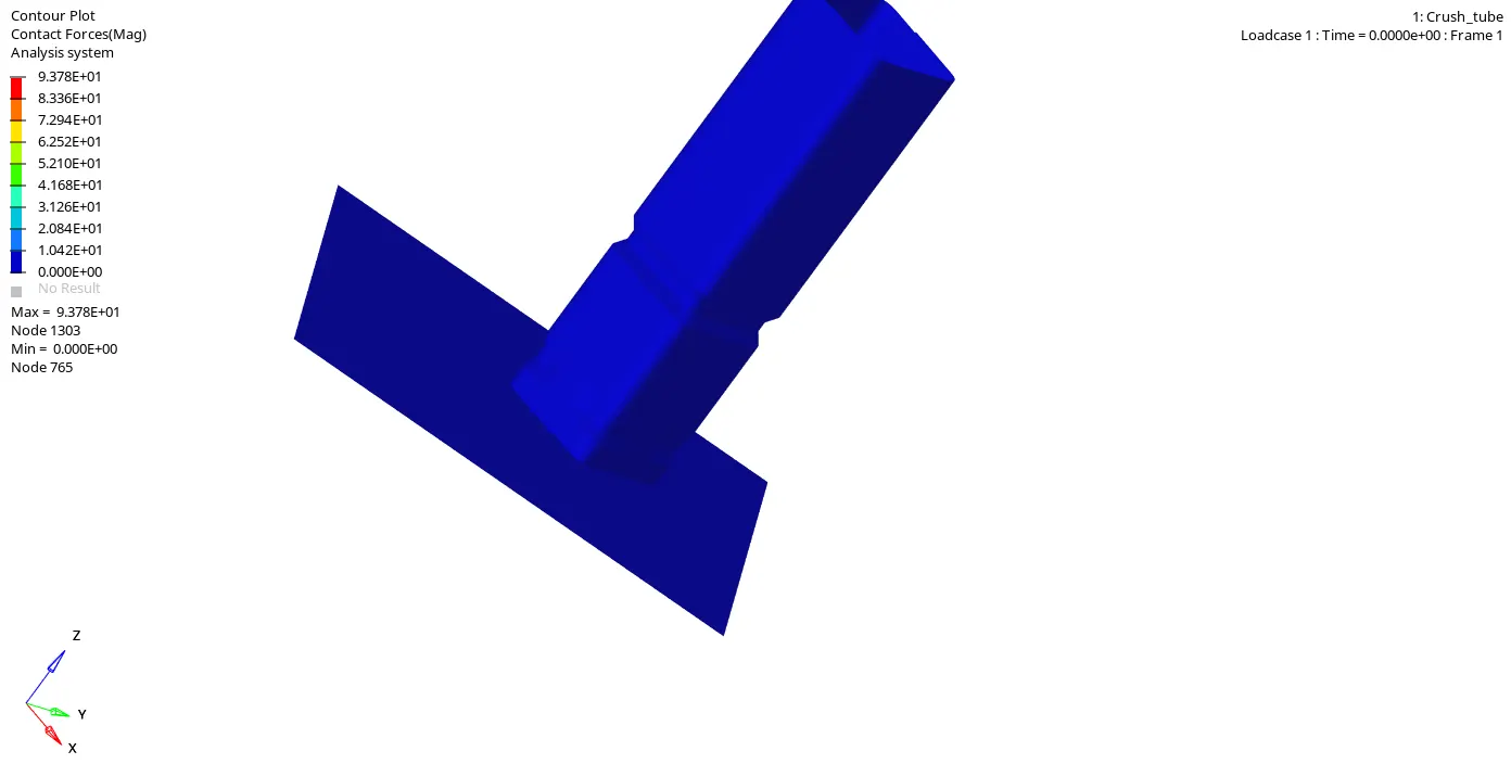
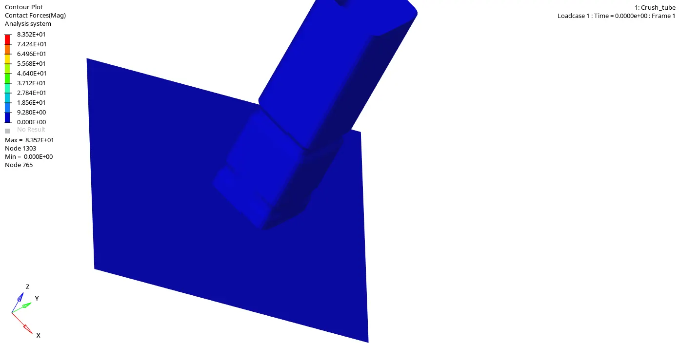
The force that created during the impact of the two different elements due to deformation. This force tends the tube to reduction in size and the elements to crush durin g deformation, while the penetration is zero till the force reaches the lower part of the tube and after some moments the contact force is created and the peak is attained makes the model to deform badly. The displacement of the element are calculated. The lower part is not so much displaced because it is fixed and the upper part is displaced so ruoghly because of the rbody force is from the top.
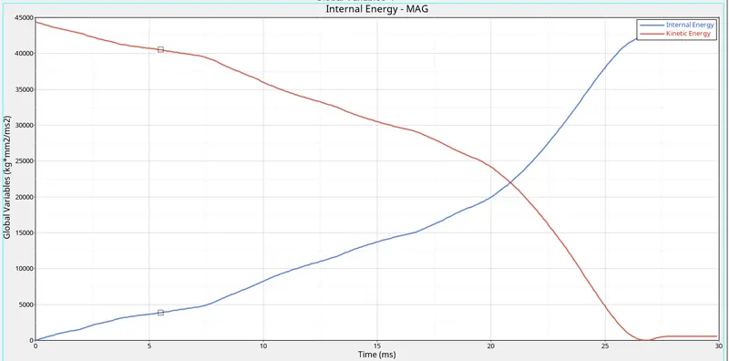
Graph plot : Internal and kinetic energy vs Time
from the graphs we can say that kinetic energy is high before the simulation starts because of the rbody force and it gradually decreases with increase in the internal energy of the system which means the energy is converted into other form of energy(kinetic to internal) and this makes the total energy of the system to remain constant straight line. Before the last time step the total energy decreases with the small increase in the kinetic energy. This is because the retracts the penetration of the slave node into the master segment.and at the end of the simulation the model is pushed back because of the resistive forces that push back the penetration of the element during the deformation.
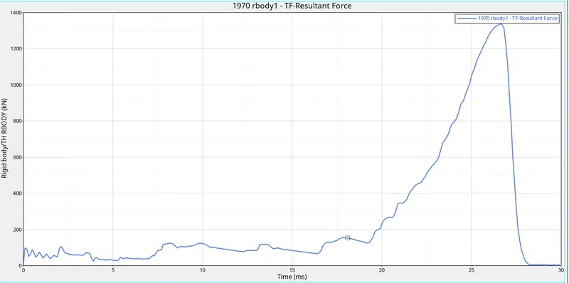
Graph plot : Resultant force vs Time
- CASE 3 : Create the type 11 contact and run
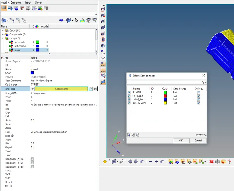
In this case the Type11 contact interface is used. The main limitation of the type7 is that it cannot approach with the edge to edge contact interface. So that is covered in the Type11.For most of the crash applications the type7 interface is used. So the combination of type7 and 11 is used in this case. The solver uses the edge to edge detection with the type 7 input parametres.
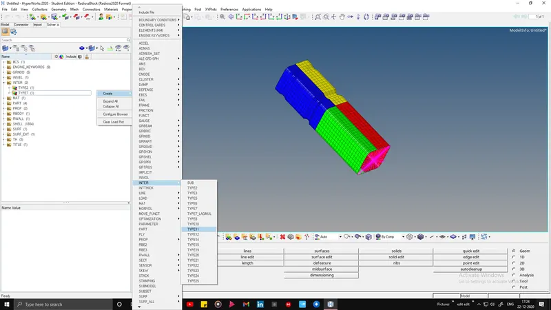
PARAMETRES USED:
Slave and master: All components,
I_stf:affects how the stiffness of the interface is calculated(I_stf=4),
I_gap: Determines how the size of the gap is calculated(I_gap=2),
I_del: The deletion happens when the master segment is removed from the contact when all/one linked element is deleted and the slave node which becomes free that are removed from the contact. (I_del=2),
St_min: Specify a minimum stiffness in the contact to avoid too soft contact. (St_min=1000N/mm),
I_form: The formulation of the sliding forces using viscous/stiffness parametres of the interface. (I_form=2),
Gapmin: minimum gap defined for the activation of the interface. (gapmin>=0.5mm),
Inacti: restricts the initial penetration of the slave node into the master segment. (inacti=6).
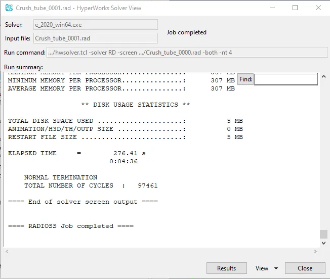
after assigning all the required data we will continue with simulation by clicking on RADIOSS button in analysis tab.we will make a seperatevfolder for each simulation type.the belowimage shows the simulation time that took for this case
Graph plot : Internal and kinetic energy vs Time
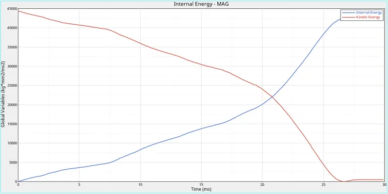
The kinetic energy is high before the simulation starts because of the rbody force and it gradually decreases with increase in the internal energy of the system.At 25th ms of the simulation the force is fully stopped and the energy curve becomes constant till the last time step of the simulation.This means the energy is converted into other form of energy(kinetic to internal) and this makes the total energy of the system to remain constant straight line. Before the last time step the total energy decreases with the small increase in the kinetic energy. The time taken by the solver to compute the energy changes are quicker in this case when compared to the other two cases before. At the end of the simulation the model is pushed back because of the resistive forces that push back the penetration of the element during the deformation.
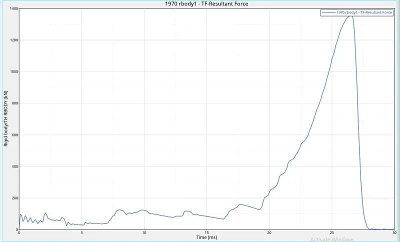
Graph plot : Resultant force vs Time
- CASE 4 : Remove both notches and remove boundary condition on rigid body node then run.
Here in this case the notch in the model is aligned to the normal geometry and make it as flat in all sides. This is done through the command Geometry>node edit>align or pressing the shortcut command shft+F8
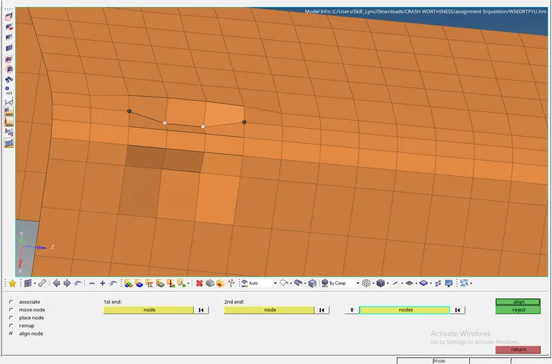
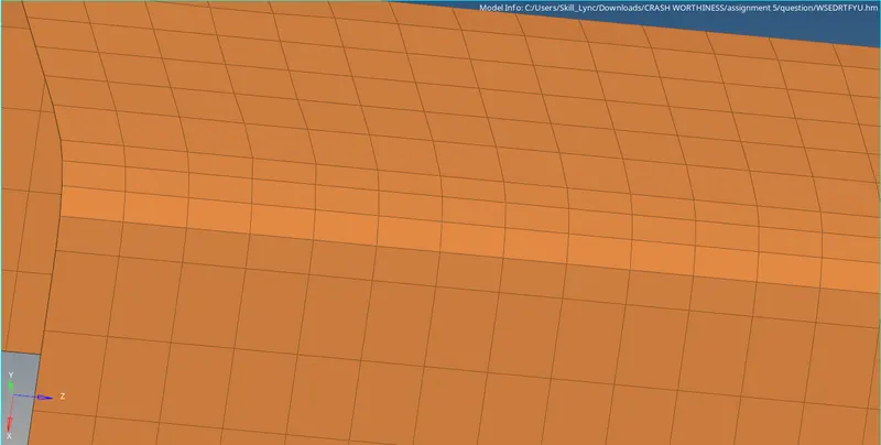
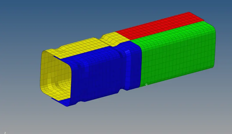
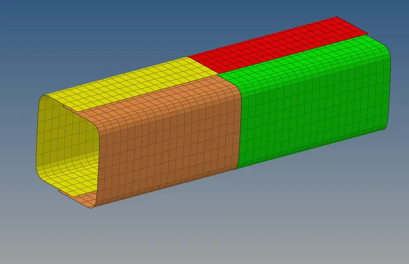
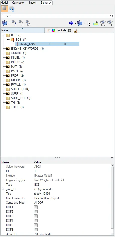
In this case the boundary conditions are deleted from the solver tab. When the boundary conditions(BCS) are deleted the Degree of Freedom(DoF) for all the elements are free to move in any direction(both translational and rotational).Then the analysis is done and the output file is saved in the local directory file path. To see the simulation results the .h3d file is opened.The time history file is also created for all the parts in the model. Both the simulation results and the plots are shown in the below image.
after assigning all the required data we will continue with simulation by clicking on RADIOSS button in analysis tab.we will make a seperate folder for each simulation type.the belowimage shows the simulation time that took for this case.
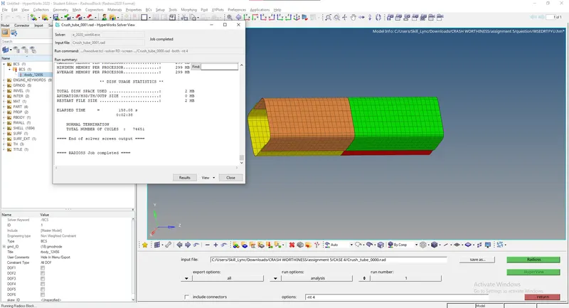
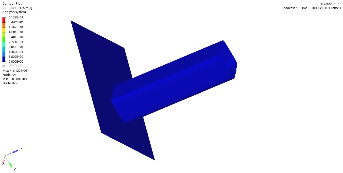
The contact forces that is created from the start is displaced to the bottom of the model suddenly because there is no notch in the model. so the force is transfered all its energy to the bottom.
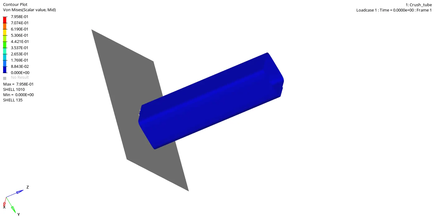
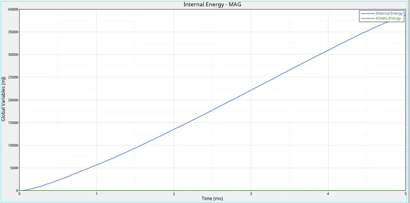
Graph plot : Internal and kinetic energy vs Time
Due to the Rwall fixed the displacement is maximum at the top. And the displacement occurs at the all the parts of the model.deletion of the boundary conditions make the changes in the internal and the kinetic energies of the parts.
Due to the no bcs card the oscillation is more and the locking doesn't happens.
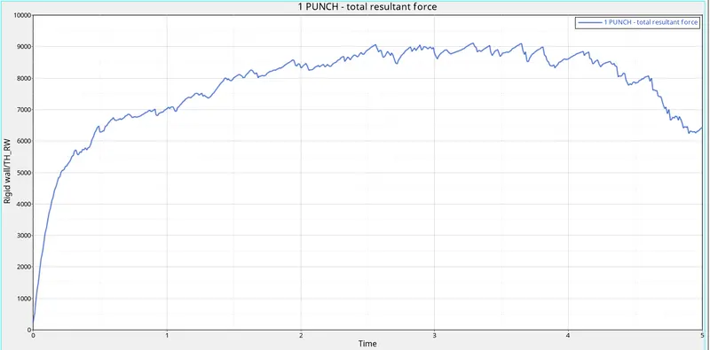
Graph plot : Resultant force vs Time
CASE 5 : Create a new notch in the middle ,select the whole section and run.
In this case, the notch is created at the centre of the model.The type 11 interface is used with the bcs card is deleted.Due to the type 11 interface the computation time for the solver is increased than the type7 contact. But the accuracy of the model is more in type11 than in the type7.
Interface Type-11 : Edge to Edge Contact :
- This interface simulates impact between edge to Edge or lines. A line can be a beam or truss element or a shell edge or spring elements. In association with interface TYPE7, interface TYPE11 solves the locking cases
- Defined by identifying master and slave lines (edges)
- Impacts occur between a master and a slave line. A slave line can impact on one or more master lines. A line can belong to the master and the slave side. This
allows self-impact. - Works similar to Type 7 in terms of Penalty formulation, Gap definition and Search method
- Uses complicated mathematical algorithms; therefore, it is strongly advisedto use it only when necessary. A huge interface TYPE11 can slow down the computation.
the following images shows hownotch is created in the middle of crashtube.
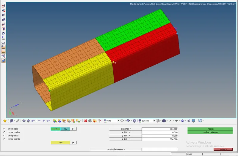
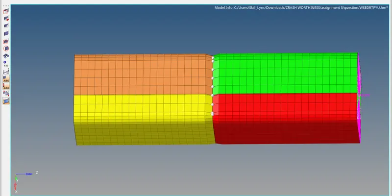
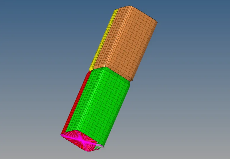
Then the analysis is done for the model and saved in the new lacal directory file path.The .h3d and .T01 file is opened to the simulation results.
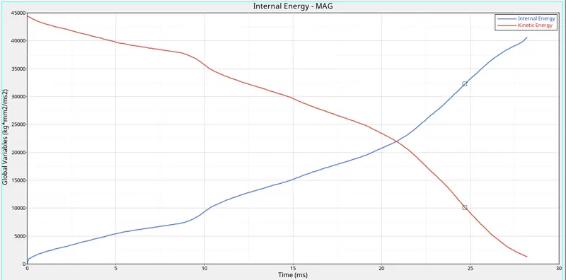
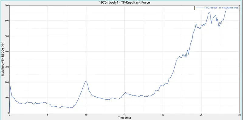
due to presence of notch at the centre makes the deformation to starts at the middle of the model and the force is increased at the bottom. The bottom is fixed so the whole tube is flat at the end of the simulation.and because of dispalcement of the force from the top to the notch, it buldges at the middle and due to fixed point at the bottom it shrinks in the area.
- CASE 6 : Create a new notch with nodes only from opposing 2 faces and run.
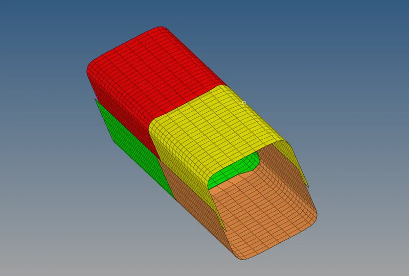
Here in this case we need to make the notch at the opposite faces so we can make it easier by removing the notches from other two opposite sides and then we will proceed for simulation.
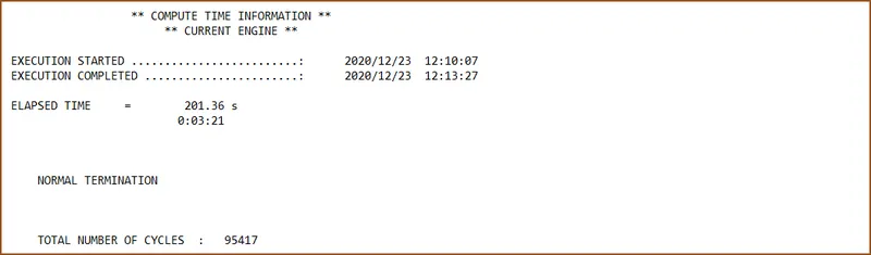
after assigning all the required data we will continue with simulation by clicking on RADIOSS button in analysis tab.we will make a seperate folder for each simulation type.the below image shows the simulation time that took for this case.
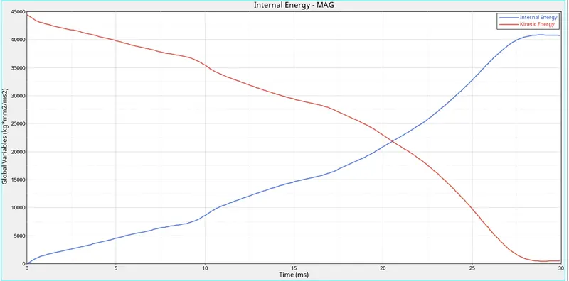
Graph plot : Internal and kinetic energy vs Time
The change in the kinetic energy and the internal energy of the body happens. due to the fixed point at the bottom(rwall) the tube crashed and becomes flat.internal energies of the parts are so high that it absorbed the kinetic energy of the rbody force. Due to the deletion of the bcs card the elements are deformed and spread to the different direction.
beacause of the notch at the middle of the model the force deforms the model from the middle that not having notch(vertical face) and the notch face is shrinked during the deformation.
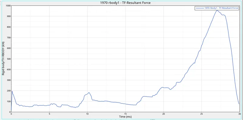
Graph plot : Resultant force vs Time
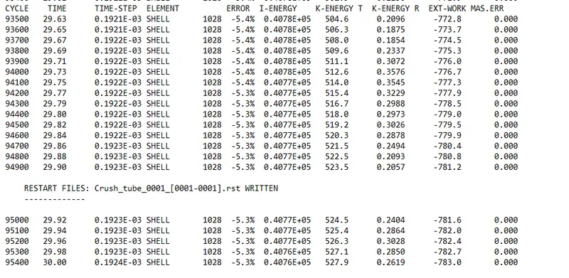
After the analysis, we will open the engine file obtained Crush_tube_0001.out via notepad to check the energy and mass error percentages.
Conclusion :
- cleanedup the geometrical errors and Created the mesh for bumper assembly with mesh size of 6mm.
- studied how the different types of contact affects different results in all 6 cases and found out that presence of notch makes the energy ansorbtion more quicker and beside that the presence of notch in different places makes differences in stiffness factor.