Assignment 5
OBJECTIVE:
The manin objective of this challange is to understand the concepts of interface contacts and its application. Also apply the same to the given model by making some changes as given below and study the effects.
- Create the mesh for bumper assembly,mesh size should be 6mm.
- Run the crash tube model as it is.
- Change the Inacti=6 and run.
- Create the type 11 contact and run.
- Remove both notches and remove boundary condition on rigid body node then run.
- Create a new notch in the middle ,select the whole section and run.
- Create a new notch with nodes only from opposing 2 faces and run.
PROCEDURE:
Mesh the given bumper model.
STEP 1) Import the given model using IMPORT MODEL option from Hypermesh.
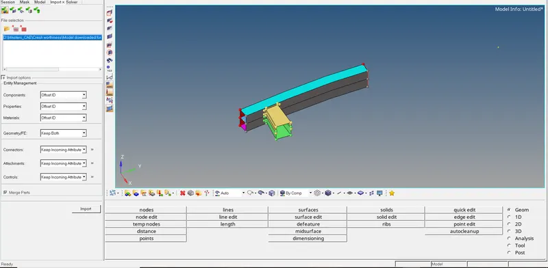
FIG 1. IMPORTING A MODEL
STEP 2) Clean the geometry using quick edit or F11 option. Also utilize trim and extend option if necessary.
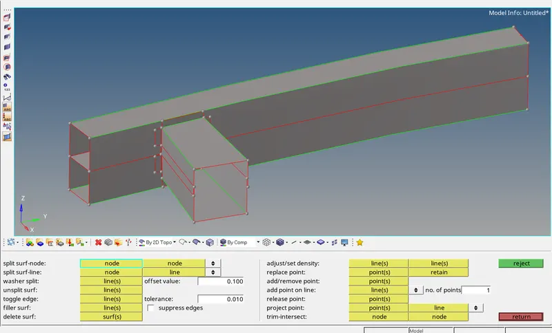
FIG 2. CLEANING UP A MODEL
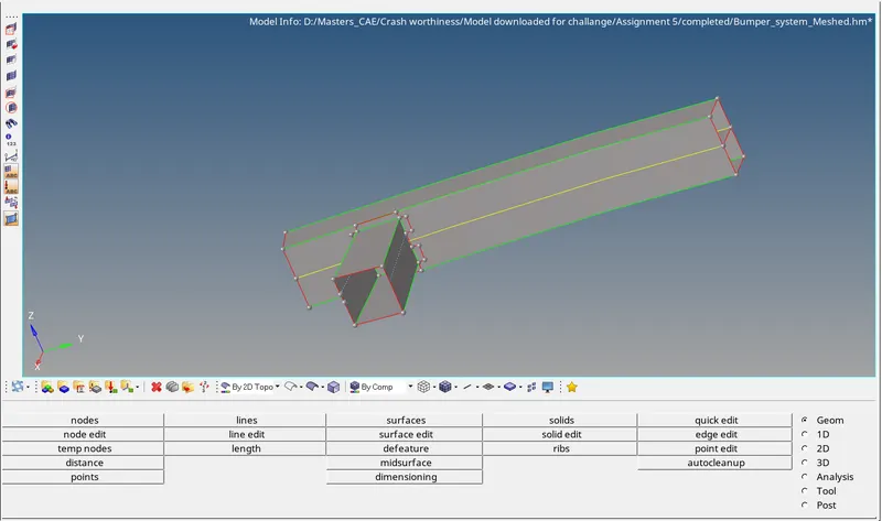
FIG 3. CLEANED MODEL
STEP 3) After cleaning the deometry next is to mesh the bumper surface. To aceive this, use 2D > automesh or F12 button. Give mesh 6 mm.
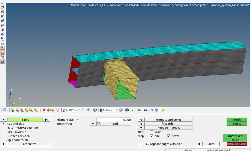
FIG 4.MESHING UP A MODEL
CASE I:
The first case is done by running the given crash tube starter file in Rdioss as it is and the reults are plotted.
STEP 1) Import the given starter file.
STEP 2) Create TH part and change the entity id to components and select all the components listed.
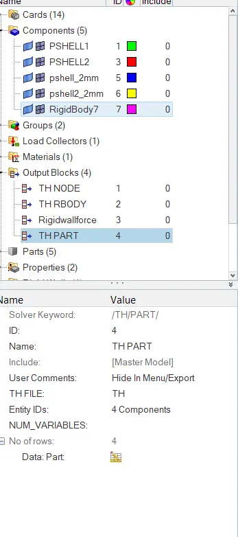
FIG 4.1 TH PART
STEP 3) Run the simulation using Anlaysis > Radioss option.
Here the interface type introduced is type 7 - Node to Surface contact.
Type 7 :
It is a general purpose interface, can simulate all types of impact between slave nodes and master surface. Since slave nodes belong to master surface, autoimpact is highly possible. It uses penalty method which introduces resistive force (Non-linear) on the slave node as soon it reaches the gap between the slave and master segment. It introduces cylindrical gap around the edges to interupt the nodes approaching sidewise to the master surface. Timestep is inversely proportional to stiffness. We have to have an eye on stiffness value, so that timestep lies within the range for the simulation.
INTERFACE PARAMETERS:
Igap : Determines how the size of the gap is calculated.
Gapmin : Minimum gap for activating interface
Inacti : Action to take if initial penetration exists
Istiff : Used to calculate the stiffness of interface.
Iform : Friction Formulation
Stmin : Min stiffness to use in interface.
Idel : Decides what to do if an element fails
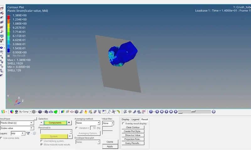
FIG 5.PLASTIC STRAIN REPRESENTATION
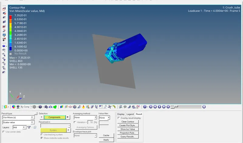
FIG 6.VON-MISES STRESS REPRESENTATION
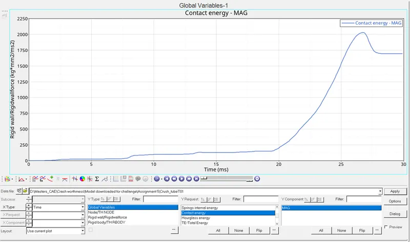
FIG 7.CONTACT ENERGY REPRESENTATION
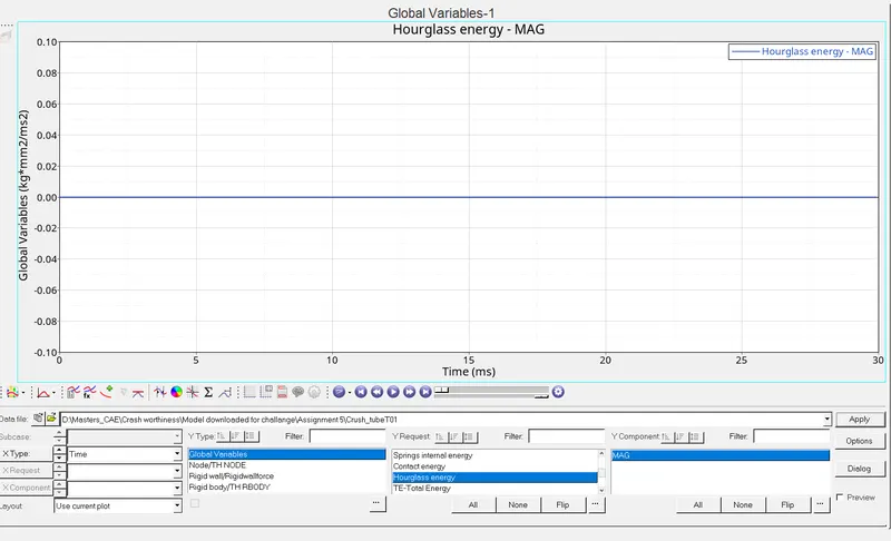
FIG 8. HOURGLASS ENERGY REPRESENTATION
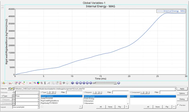
FIG 9. INTERNAL ENERGY REPRESENTATION
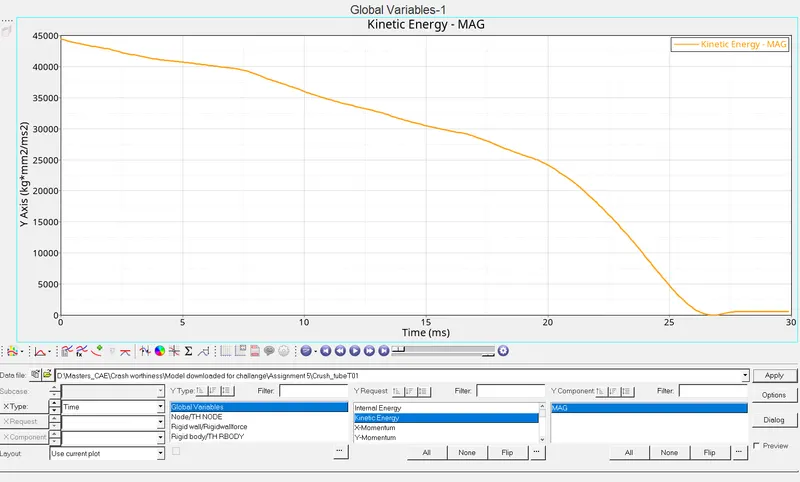
FIG 10. KINETIC ENERGY REPRESENTATION
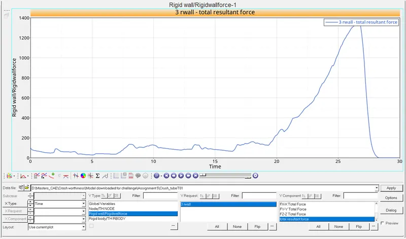
FIG 11. RIGID WALL FORCE REPRESENTATION
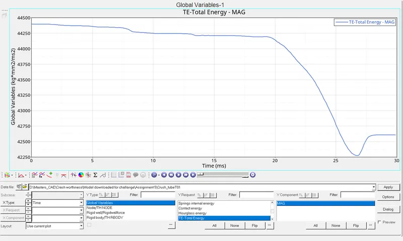
FIG 12. TOTAL ENERGY REPRESENTATION
CASE II:
The next case is proceded by altering the Inacti value to 6 in the crash tube starter file and the reults are plotted.
STEP 1) Import the given starter file.
STEP 2) Change the Inacti value to 6 in the radioss.
STEP 3) Run the simulation using Anlaysis > Radioss option.
Here the interface type introduced is same as case I type 7 - Node to Surface contact.
INTERFACE PARAMETERS:
Igap : Determines how the size of the gap is calculated.
Gapmin : Minimum gap for activating interface
Inacti : Action to take if initial penetration exists
Istiff : Used to calculate the stiffness of interface.
Iform : Friction Formulation
Stmin : Min stiffness to use in interface.
Idel : Decides what to do if an element fails
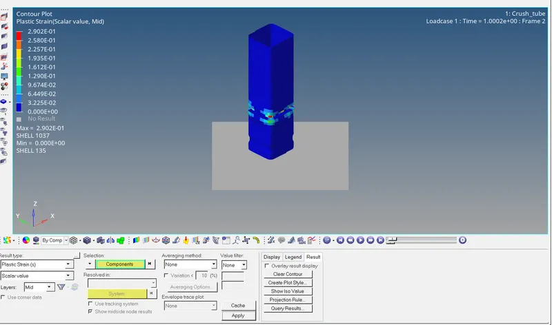
FIG 13. PLASTIC STRAIN REPRESENTATION
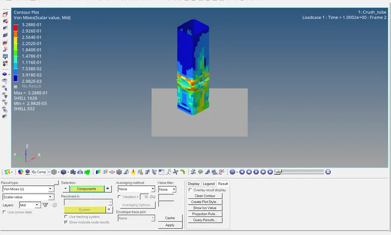
FIG 14. VON-MISES STRESS REPRESENTATION
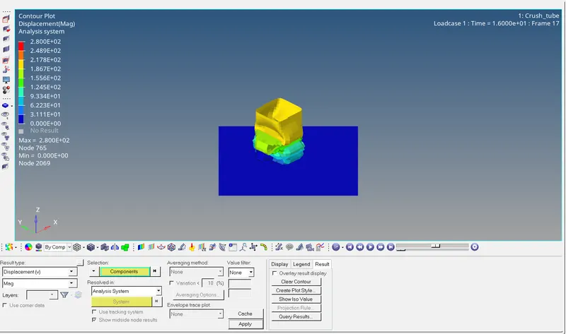
FIG 15. DISPLACEMENT REPRESENTATION
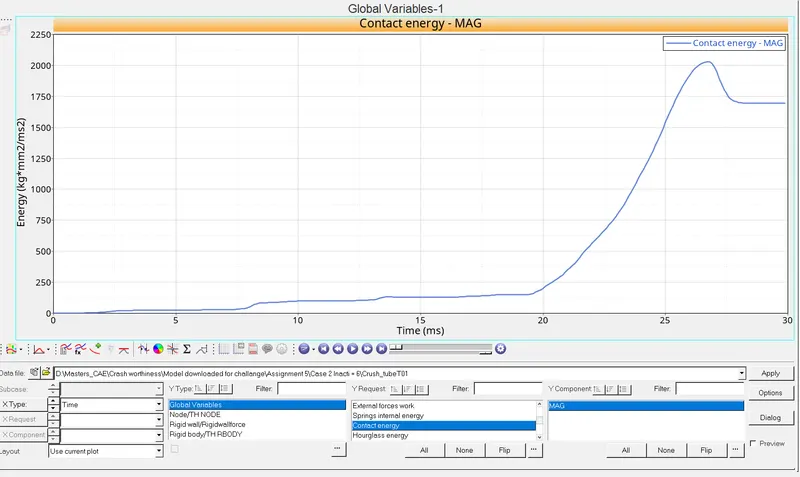
FIG 16. CONTACT ENERGY REPRESENTATION
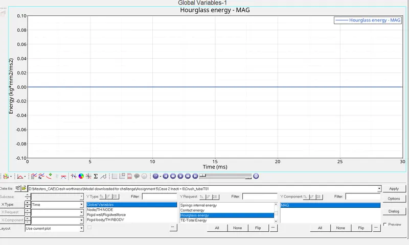
FIG 17. HOURGLASS ENERGY REPRESENTATION
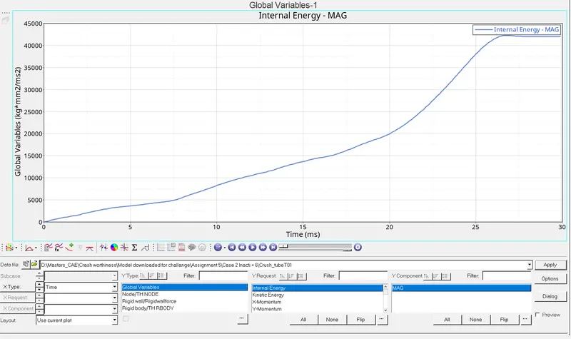
FIG 18. INTERNAL ENERGY REPRESENTATION
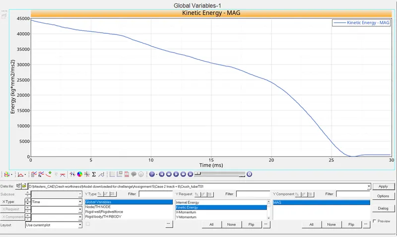
FIG 19. KINETIC ENERGY REPRESENTATION
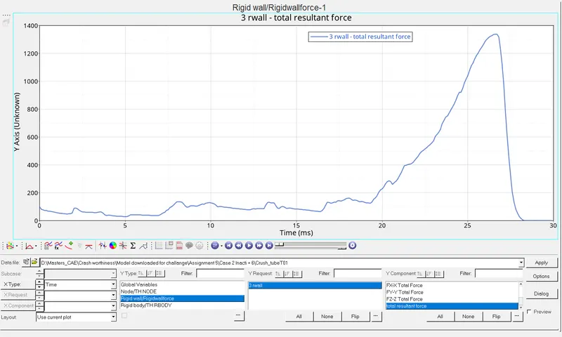
FIG 20. RWALL FORCE REPRESENTATION
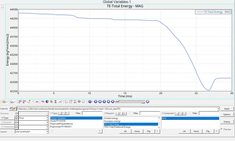
FIG 21. TOTAL ENERGY REPRESENTATION
OBSERVATION:
By introducing the Inacti = 6, the initial penerations is computed and gap is reduced before the start of the simulation. If penetration of slave nodes happens into master segment, it leads to instability of the simulation. With comparsion to Inacti=5, it is 30% more accurate.
CASE III:
The next case is proceded by altering the interface type from type 7 to type 11 (EDGE tO EDGE CONTACT) in the crash tube starter file and the reults are plotted. The interface parameters are same as of type7 in Penalty formulation, Gap definition.
STEP 1) Import the given starter file in hypercrash. Use File > Import > Radioss. After selecting, the pop up screen comes up as below.
1.1) Paste the location in the selection C tab and hit ok.
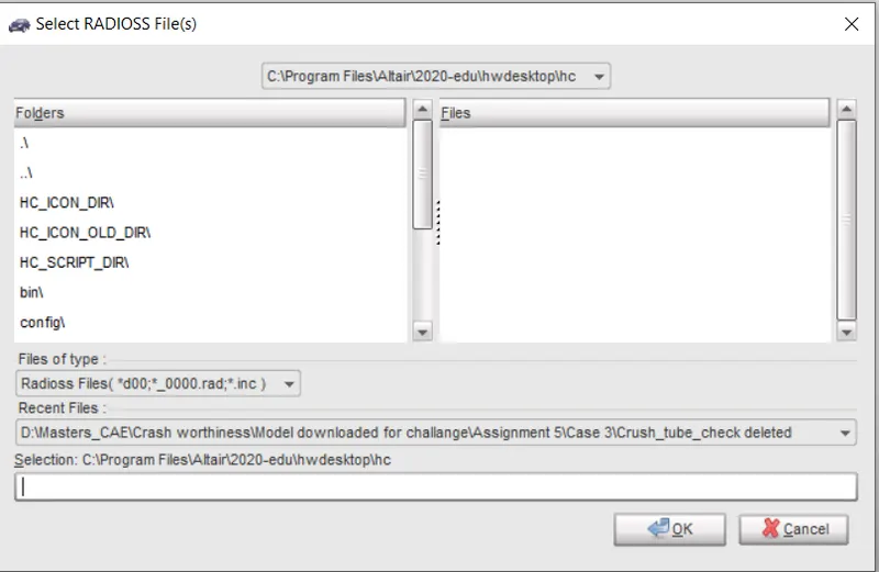
FIG 22 IMPORTING FILE IN HYPERCRASH
STEP 2) Change the interface type to type 11.
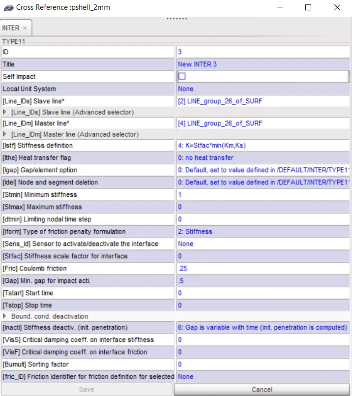
FIG 23 TYPE 11 PARAMETERS
STEP 3) Export from Hypercrash and Import in radioss. Run the simulation using Anlaysis > Radioss option.
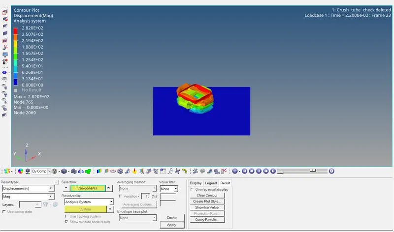
FIG 24 DISPLACEMENT REPRESENTATION
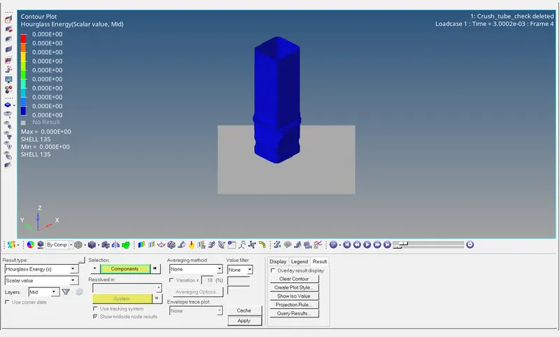
FIG 25 HOURGLASS ENERGY REPRESENTATION
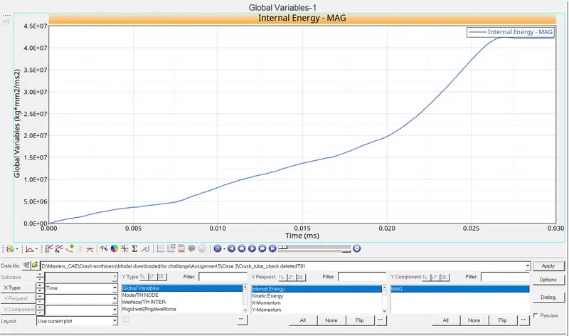
FIG 26 INTERNAL ENERGY REPRESENTATION
FIG 27 INTERNAL ENERGY REPRESENTATION
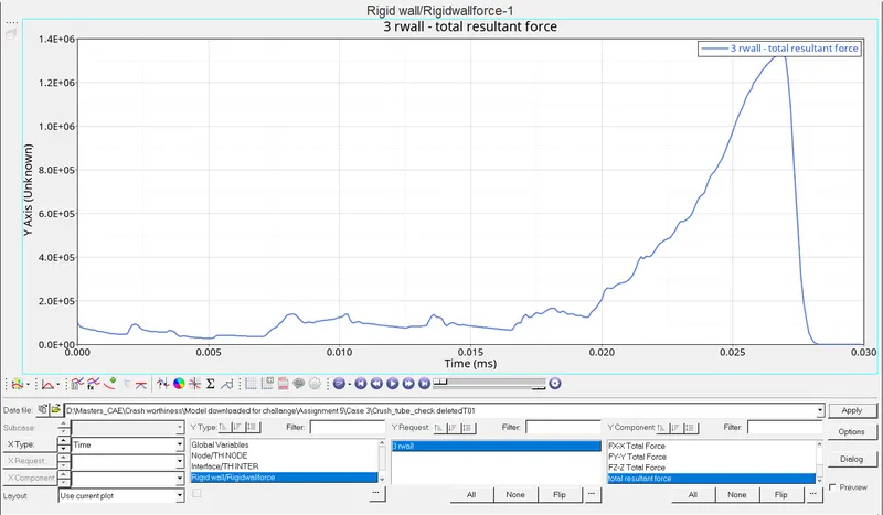
FIG 28 RWALL FORCE REPRESENTATION
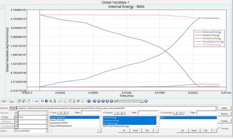
FIG 29 COMBINED ENERGIES REPRESENTATION
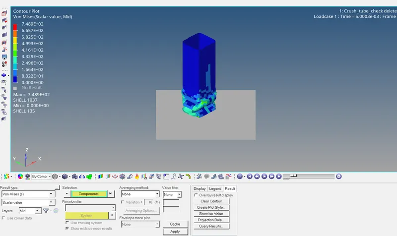
FIG 30 VON MISES STRESS REPRESENTATION
OBSERVATION:
This type 11 interface, have edge to edge contact and overcomes the disadvantage of Type 7 interface.
CASE IV:
The next case is done by removing the boundary condition and also the notch provided in the crash tube and the results are plotted.
STEP 1) Import the given starter file.
STEP 2) Delete the Boundary conditions adhered to the rigid body in hypergraph.
STEP 3) Notch is removed in Hypermesh with the help of align node option and project option.
STEP 4) Run the simulation using Anlaysis > Radioss option.
Here the interface type introduced is type 11 - Edge to Edge contact.

FIG 31. VON MISES STRESS REPRESENTATION
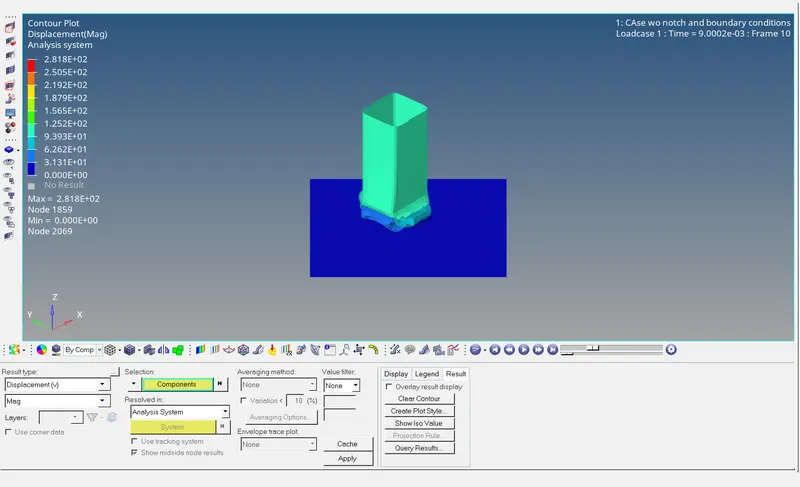
FIG 32. DISPLACEMENT REPRESENTATION
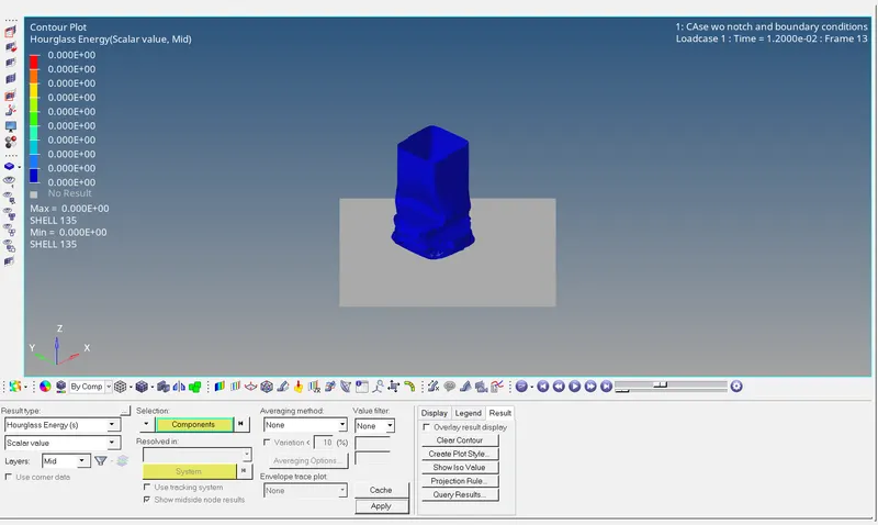
FIG 33. HOURGLASS ENERGY REPRESENTATION
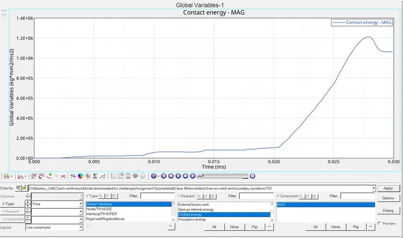
FIG 34. CONTACT ENERGY REPRESENTATION
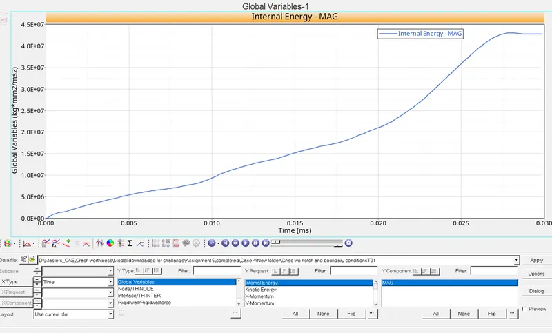
FIG 35. INTERNAL ENERGY REPRESENTATION
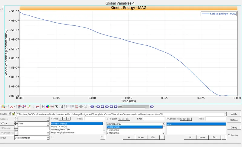
FIG 36. KINETIC ENERGY REPRESENTATION
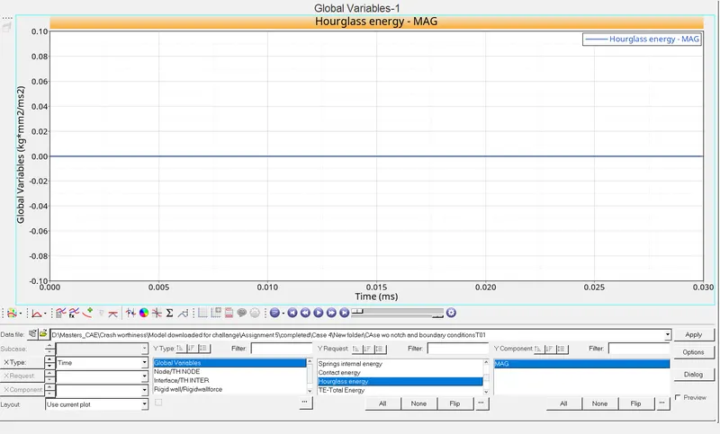
FIG 37. HOURGLASS ENERGY REPRESENTATION
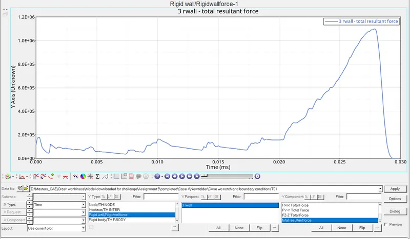
FIG 38. RWALL FORCE REPRESENTATION
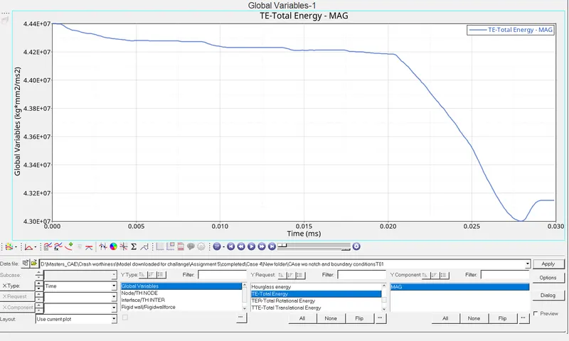
FIG 39. TOTAL ENERGY REPRESENTATION
OBSERVATION:
Removal of notch prevents the absorption of energy and this case experiences max stress value.
CASE V:
The next case is done by creating the notch provided in the middle for the whole section in the crash tube and the results are plotted.
STEP 1) Import the given starter file.
STEP 2) Create the notch in the middle for the whole section using translate option..
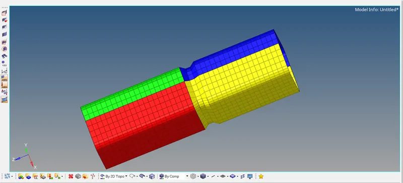
FIG 39.1 NOTCH REPRESENTATION
STEP 3) Run the simulation using Anlaysis > Radioss option.
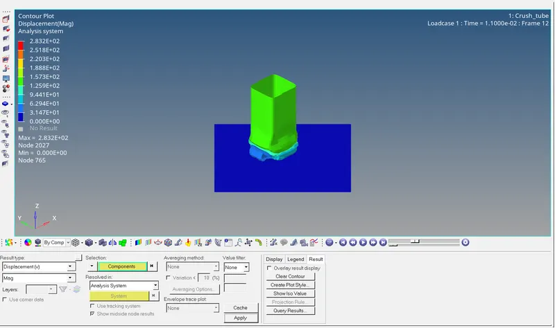
FIG 40. DISPLACEMENT REPRESENTATION
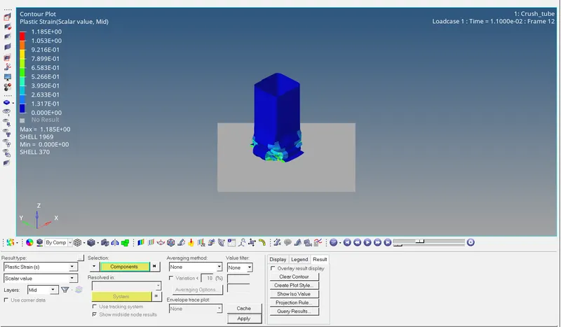
FIG 41. PLASTIC STRAIN REPRESENTATION
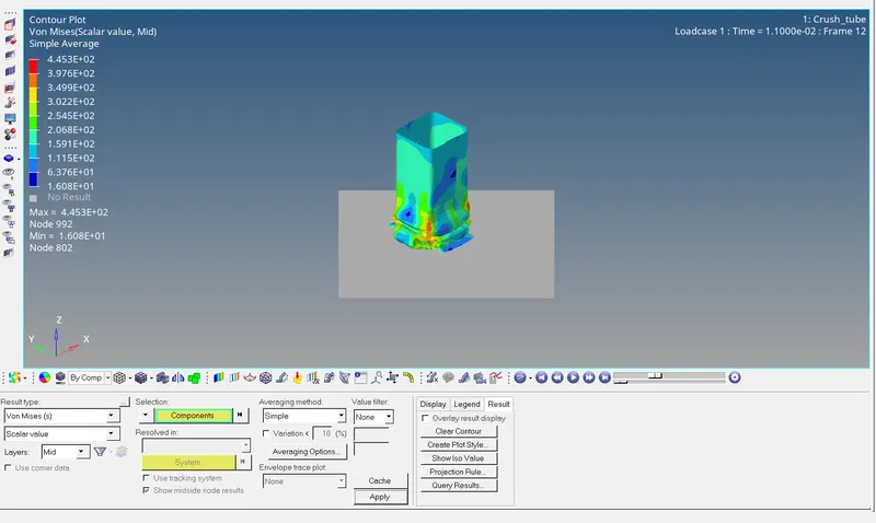
FIG 42. VON MISES REPRESENTATION
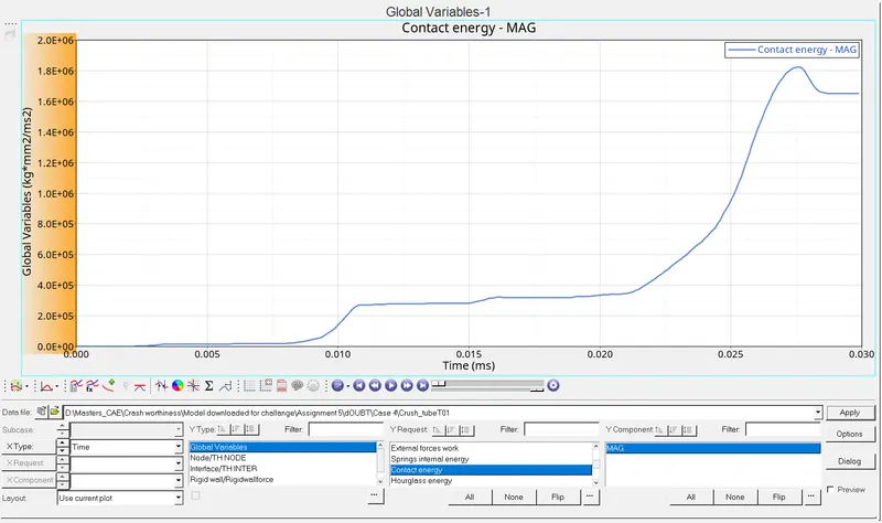
FIG 43. CONTACT ENERGY REPRESENTATION
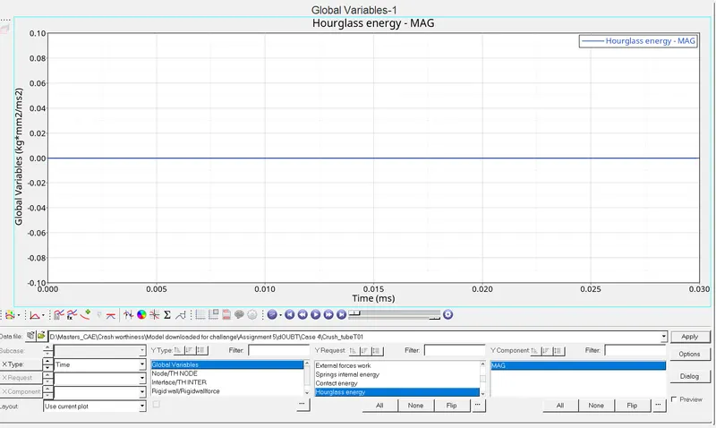
FIG 44. HOURGLASS ENERGY REPRESENTATION
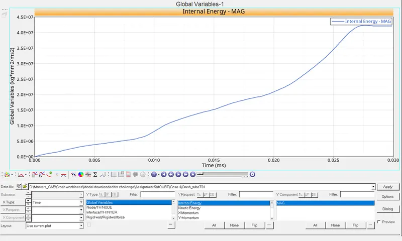
FIG 45. INTERNAL ENERGY REPRESENTATION
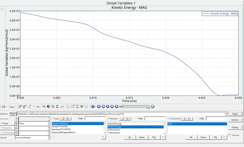
FIG 46. KINETIC ENERGY REPRESENTATION
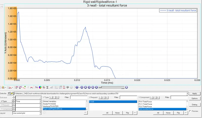
FIG 47. RIGIDWALL REPRESENTATION
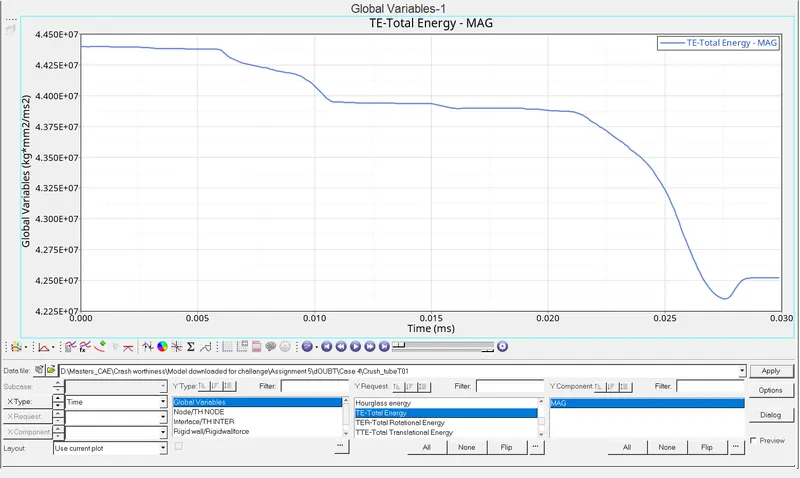
FIG 48. TOTAL ENERGY REPRESENTATION
OBSERVATION:
Notches at the middle absorb the kinetic energy of the tube and is stored as Internal energy and stress distribution is less compared to the model without notches.
CASE VI:
The next case is done by creating the notch provided in the middle for the whole section in the crash tube and the results are plotted.
STEP 1) Import the given starter file.
STEP 2) Create the notch on one face and on the opposite face using translate option.
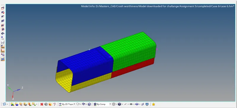
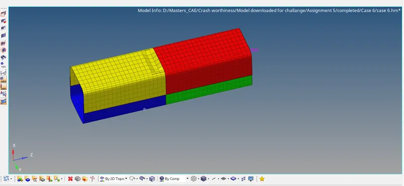
FIG 49. NOTCH REPRESENTATION FIG 50.NOTCH REPRESENTATION
STEP 3) Run the simulation using Anlaysis > Radioss option.
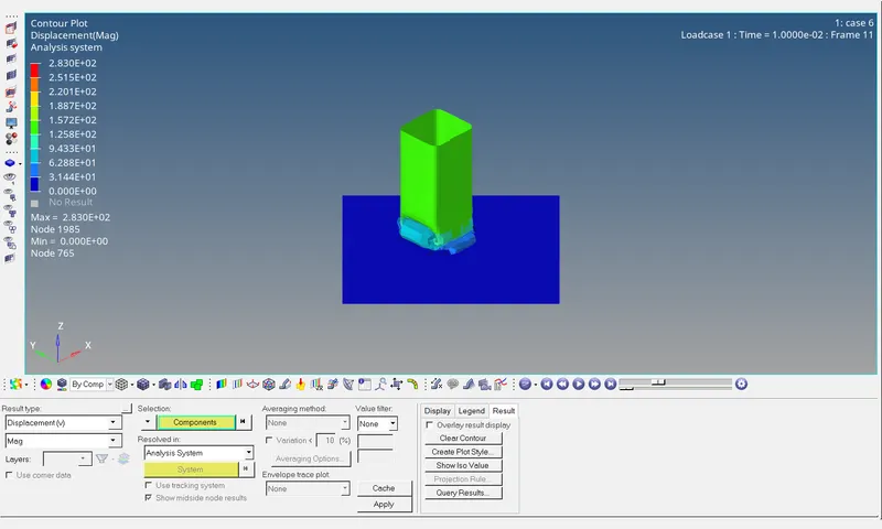
FIG 50. DISPLACEMENT REPRESENTATION
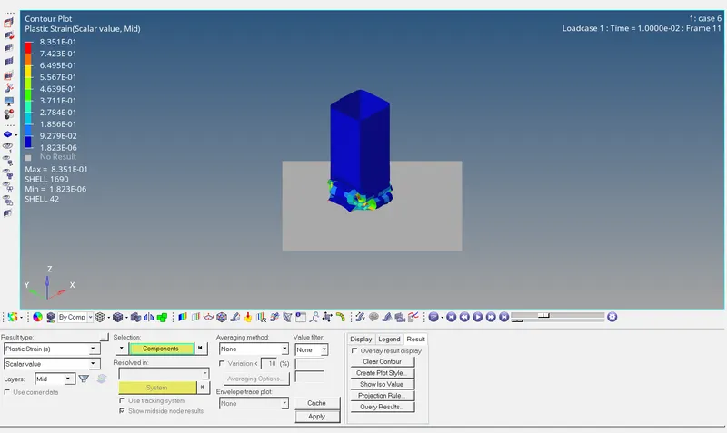
FIG 51.PLASTIC STRAIN REPRESENTATION
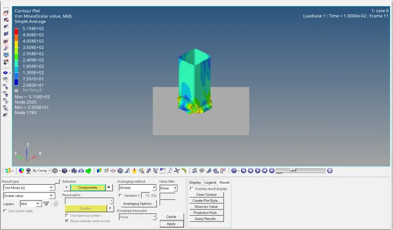
FIG 52.VON MISES STRESS REPRESENTATION
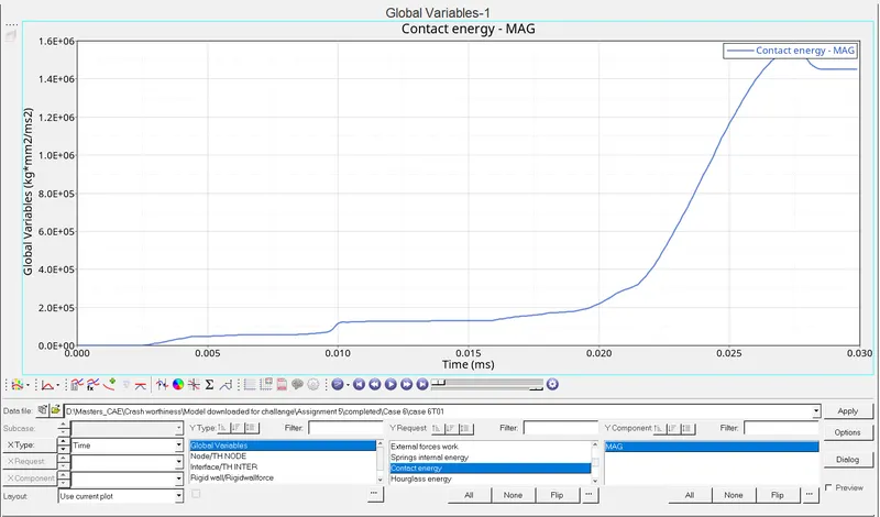
FIG 53 .CONTACT ENERGY REPRESENTATION
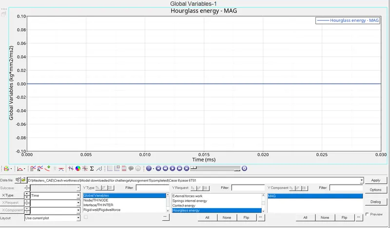
FIG 53. HOURGLASS ENERGY REPRESENTATION
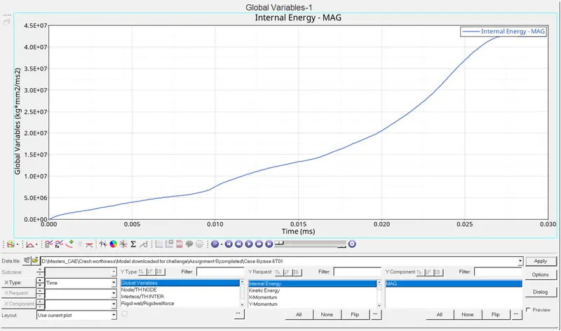
FIG 54. INTERNAL ENERGY REPRESENTATION
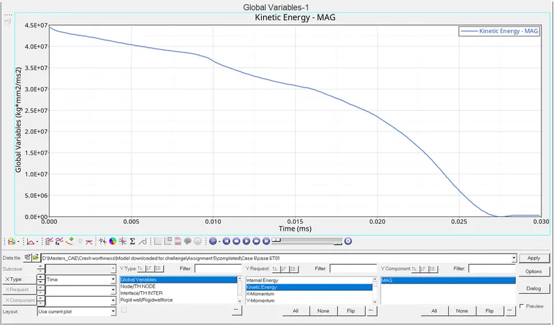
FIG 55. KINETIC ENERGY REPRESENTATION
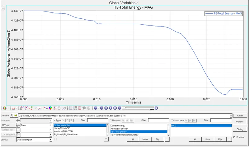
FIG 56. TOTAL ENERGY REPRESENTATION
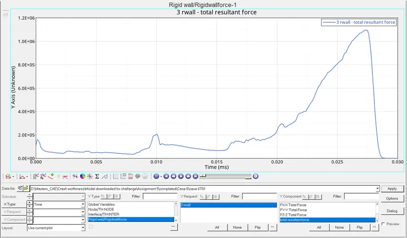
FIG 57. RIGID WALL FORCE REPRESENTATION
OBSERVATION:
Due to the notch present, most of the stress is taken by the notches as in previous case.
EFFECT OF NOTCH:
During simulation, the notch gets crushed first before the tube. Due to the presence of notch, the absorbption of energy of the crash tube during simulation increases compared to the case where notch is absent. Also stress variation is controlled by the notch present over there.
CONCLUSION:
By comparing every case mentioned above, each one has its own behaviour as its characteristics. Mass error remains nil for every case. Internal energy remains more or less same for every case. Since the notches are present at the middle they absorb more energy ( comparing Case 1 & Case 5). Hence if notches are at the middle internal energy will be more compared to the case where notches are away from middle section. Kinetic energy gradually becomes small for every cases and at the end of the crash the Kinetic energy increase with small deviation.