Assignment 4-RADIOSS Material Laws Challenge
Objective: The given model is a rupture plate , it is collided by a punch at a velocity.
For the given model, obtain the results from different cases:
- Running the model as given i.e., with failure card and material card M2_PLAS_JOHNS_ZERIL. (Named as law2_epsmax_failure)
- In Failure card change Ifail_sh=1, Dadv=1, Ixfem=1. (Named as law2_epsmax_crack)
- Delete the failure card and run the simulation. (Named as law2_epsmax_nofail)
- Delete the value of EPS_p_max and run the simulation. (Named as Law2)
- Change the material card to MAT/LAW1 with same density, Poisson’s ratio and young’s modulus.(named as law1)
- Change the material card to /MAT/LAW36(PLAS_TAB) and maintain the recommended shell properties, Provide the values in material card as given. (Named as law 36)
- Use LAW27_0000 with card image asM27_PLAS_BRIT, and maintain the recommended shell properties, Provide the values in material card as given. (Named as law 27)
Compare the above 7 cases on basis of:
1.Total number of cycles, Energy error, mass error and simulation time.
2. Notice the animation of all 5 and describe the animations in brief on the basis of whether the elements are being deleted or cracked.
3. Plot energies and notice any difference.
4. Based on all the results, which case would represent the on-field scenario.
5. Prepare a ppt/docx and list down case-by-case result and your conclusion as to why the failure happened.
INTRODUCTION:
/MAT/LAW1 (ELAST)
This keyword defines an isotropic, linear elastic material using Hooke's law. This law represents a linear relationship between stress and strain. It is available for truss, beam (type 3 only), shell and solid elements.
This material law is used to model purely elastic materials. The material stiffness is determined by only two values: the Young's modulus (E), and Poisson's ratio. The shear modulus (G) can be computed using E and ν">nu as:
G=E/2(1+ν)
Global integration approach is applied to LAW1 and shell elements, when the number of integration points through the shell thickness is different from NP=1 (membranes).
/MAT/LAW2 (PLAS_JOHNS)
- This is an elasto-plastic material model that includes strain rate and temperature effects with true stress and strain output.
- In this model the material behaves as a linear-elastic material when the equivalent stress is lower than the plastic yield stress. For higher stress values, the material behaviour is plastic, and the true stress is calculated as: σ = (a+b*εp^n) (1+cln(˙ε/˙ε0)) (1−(T^m))
- If Iflag=0, the Johnson-Cook equation parameters a, b, and n values are entered.
- If Iflag=1, experimental engineering stress and stain data can be entered for σy, UTS and εUTS and the parameters a, b and n are calculated and printed in the Starter output file. If the a, b and n parameters cannot be automatically fit, then a Starter warning message will contain important information about changes to the material input.
- The plastic yield stress should always be greater than zero. To model pure elastic behaviour, the plastic yield stress will be set to 1030.
- When εpreaches the value of εp max in one integration point, then based on the element type:
- Shell elements: The corresponding shell element is deleted.
- Solid elements: The deviatoric stress of the corresponding integral point is permanently set to 0; however, the solid element is not deleted.
- The plastic hardening exponent, n must be less than or equal to 1.
- To eliminate the effect of the strain rate, you can either set the value of c equal to 0 or the reference strain rate (ε˙0) can be set equal to 1030. There is no effect of strain rate when ε˙ is less than ε˙0.
/MAT/LAW36 (PLAS_TAB)
This law models an isotropic elasto-plastic material using user-defined functions for the work-hardening portion of the stress-strain curve (for example, stress vs. plastic strain) for different strain rates.
- The first point of yield stress functions (plastic strain vs stress) should have a plastic strain value of zero. If the last point of the first (static) function equals 0 in stress, default value of εmaxpis set to the corresponding value of εp.
- Element deletion:
- Once εp(plastic strain) reaches εp max, in one integration point, the element is deleted.
- If ε1reaches εt , the stress is reduced using the following relation:(1)
σ = E*((εm−ε1) / (εm−εt))
- If ε1(largest principal strain) reaches εm (point where stress is zero but still strain takes place), the stress in element is reduced to 0 (but the element is not deleted).
- Once ε1(largest principal strain) reaches εf (maximum tensile failure strain), the element is deleted.
- The kinematic hardening model is not available in global formulation (N=0 in shell property keyword) that is, hardening is fully isotropic.
- In case of kinematic hardening and strain rate dependency, the yield stress depends on the strain rate.
- Strain rate filtering is used to smooth strain rates.
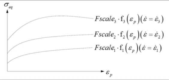
- Factor_ID f1, f2, f3 are plotted from the laboratory results at particular strain rates ε˙1, ε˙2, ε˙3.
- Separate functions must be defined for different strain rates.
- Strain rate values must be given in strictly ascending order.
- If ε˙ ≤ ε˙n , the yield stress is interpolated between fn and fn−1 .
- If ε˙ ≤ ε˙1, function f1is used.
- Above ε˙max, yield stress is extrapolated.
/MAT/LAW27 (PLAS_BRIT)
This law combines an isotropic elasto-plastic Johnson-Cook material model with an orthotropic brittle failure model. Material damage is accounted for prior to failure. Failure and damage occur only in tension. This law is applicable only for shells.
- In this model, the material behaves as a linear-elastic material when the equivalent stress is lower than the plastic yield stress. For higher stress values, the material behaviour is plastic and the stress is calculated as:
σ=(a+b*εp^n)(1+cln(ε˙/ε˙0))
Where,
Εp: Plastic strain
˙ε: Strain rate
The plasticity hardening exponent, n must be less than 1.
- This law allows the modelling of material damage and brittle failure in two principal directions (1 and 2).
- The ICCflag defines the effect of strain rate on the maximum material stress σmax">σ max
ICC strain rate computation flag = 0 (default)
ICC = 1: Strain rate effect on σ max
ICC = 2: No strain rate effect on σ max
Case setup and Execution:
Case 1: Running the model as given i.e., with failure card and material card M2_PLAS_JOHNS_ZERIL. (Named as law2_epsmax_failure)
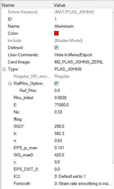
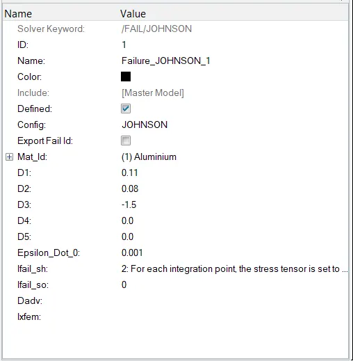
EPS_max and σ max are the failure criteria.
MATERIAL CARD:
FAILURE CARD:
Go to Analysis deck >>> Radioss >>> Save >>> run

In options, -nt 4 is indicating number of threads or number of CPU cores are 4, used to run the application.
By opening FAILURE_JOHNSON_0001.out file, we can read the Energy error, Mass error, Kinetic energy, Internal energy at cycle time.
The below figure shows the time taken for the simulation, number of cycles taken place in the simulation.
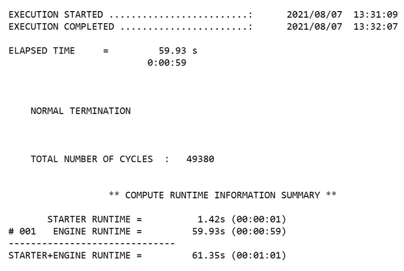
Total number of cycles = 49380.
Total runtime = 61.35 seconds.
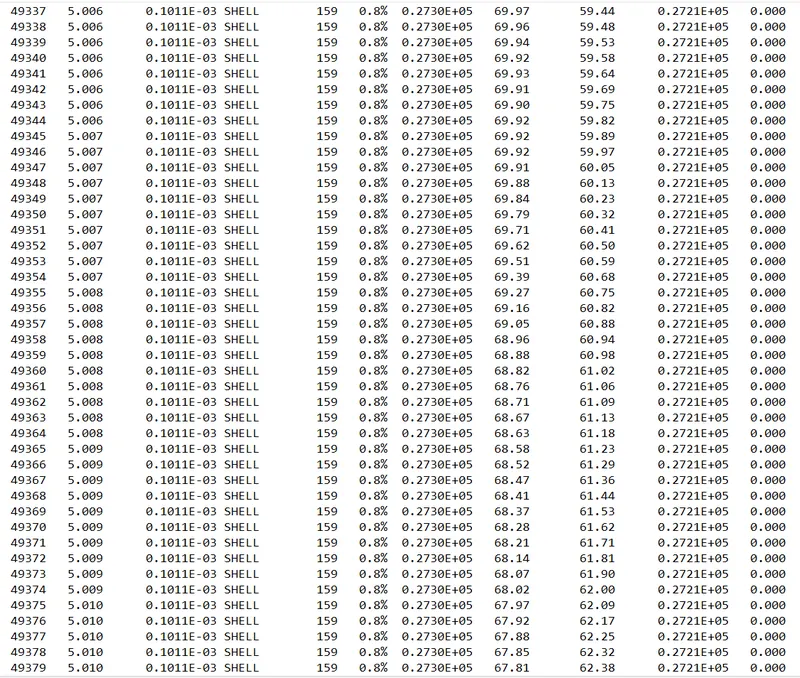
ENERGY ERROR = 0.8%
Max.Kinetic energy = 67.81 mJ
Max.Internal energy = 27300 mJ
The acceptable error is -15% to 5%.
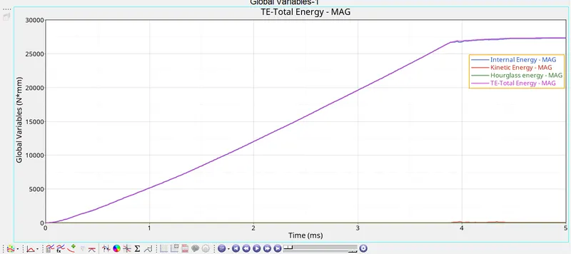
INTERNAL ENERGY: As the load is applied on rupture plate, Energy is stored due to the intermolecular displacement of the elements called as Internal energy.
The internal energy varies almost linearly upto yield point and is constant after the yield point.
KINETIC ENERGY: As the plate is acting like a clamped component, the KE of the component = 0.
HOURGLASS ENERGY: Hourglass is taken care by the recommended properties and is zero in this case.
Total energy: Summation of all internal energy and kinetic energy. It is following the same trend as Internal energy as Kinetic energy is zero.
From the above graph,
As the load is applied on the rupture plate, the plastic deformation takes place untill it reach the provided maximum strain and maximum stress.
As the plate reaches the max strain or max stress, the component fails and some elements gets removed and some elements remain in deformed shape due to plastic deformation.
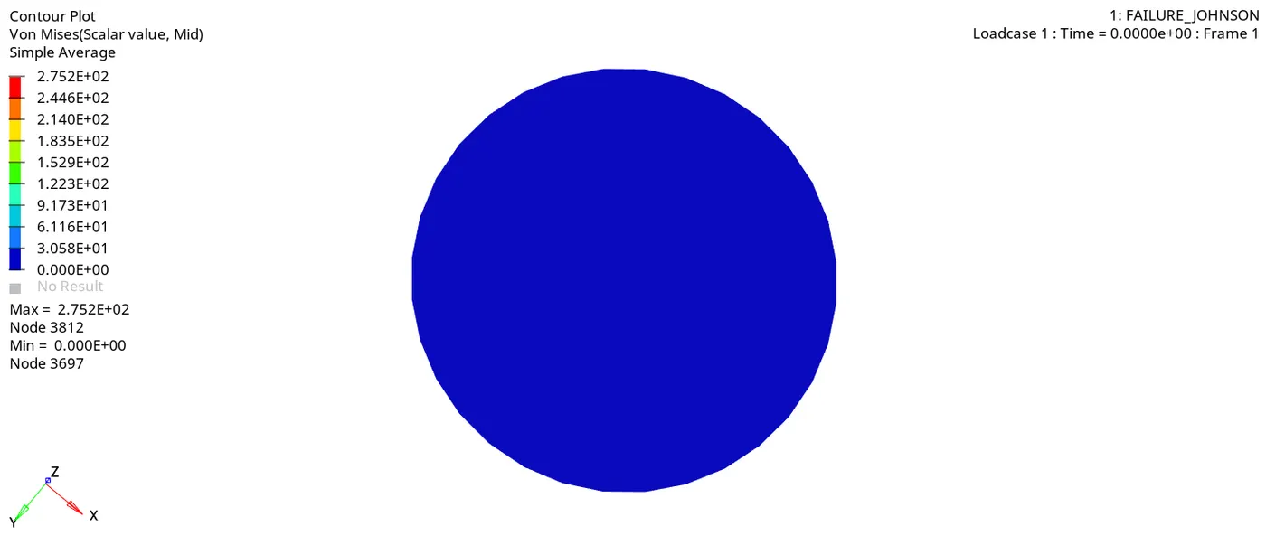
The maximum stress i.e., obtained is 275 MPA, the elements failing for max strain and max stress are blown away as shown in the figure.
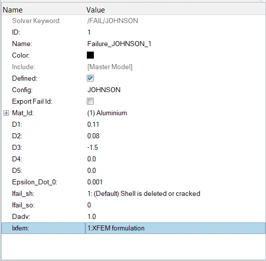
CASE 2: In Failure card change Ifail_sh=1, Dadv=1, Ixfem=1. (Named as law2_epsmax_crack)
D1, D2, D3 are the failure criteria.
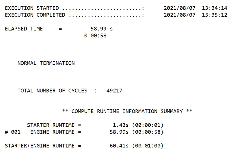
Total run time = 60.41 seconds.
Number of cycles = 49217.
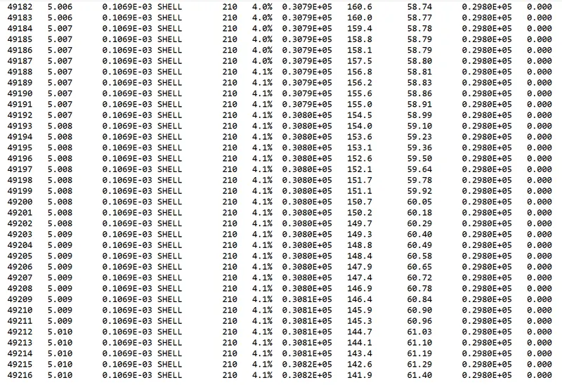
The energy error from the range of -15% to 5% is acceptable.
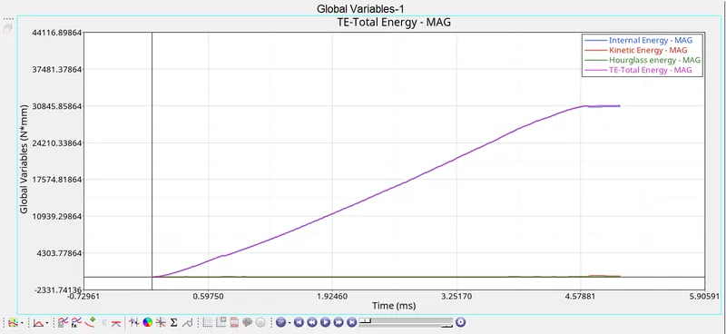
The internal energy varies almost linearly upto yield point and is constant after the yield point.
KINETIC ENERGY: As the plate is acting like a clamped component, the KE of the component = 0.
HOURGLASS ENERGY: Hourglass is taken care by the recommended properties and is zero in this case.
Total energy: Summation of all internal energy and kinetic energy. It is following the same trend as Internal energy as Kinetic energy is zero.
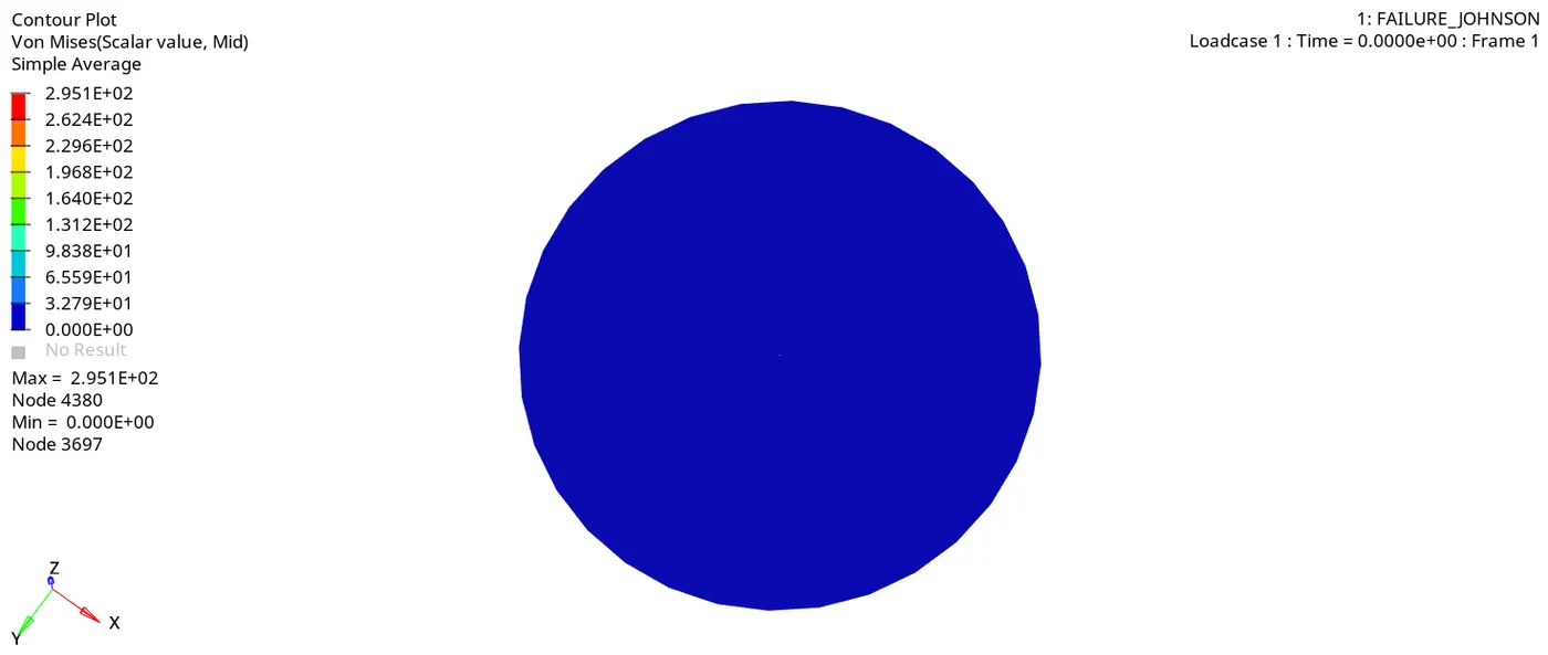
As the load is applied on the rupture plate, the plastic deformation takes place untill the strain calculated i.e., from D1, D2, D3.
As the plate reaches the max strain, the component fails and some elements gets removed and some elements which are below amx.strain remain in deformed shape due to plastic deformation.
The crack propogates as the deformation is taking place.
The maximum stress i.e., obtained is 295 MPA, the elements failing for max strain are blown away as shown in the figure.
CASE 3: Delete the failure card and run the simulation. (Named as law2_epsmax_nofail)
Failure card is deleted.

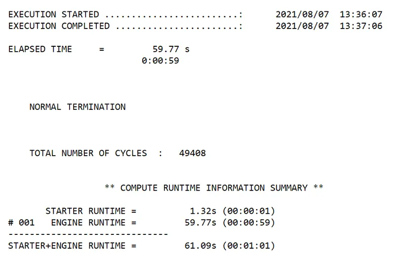
Total run time = 61.09 seconds.
Number of cycles = 49408
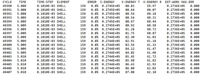
The energy error from the range of -15% to 5% is acceptable.
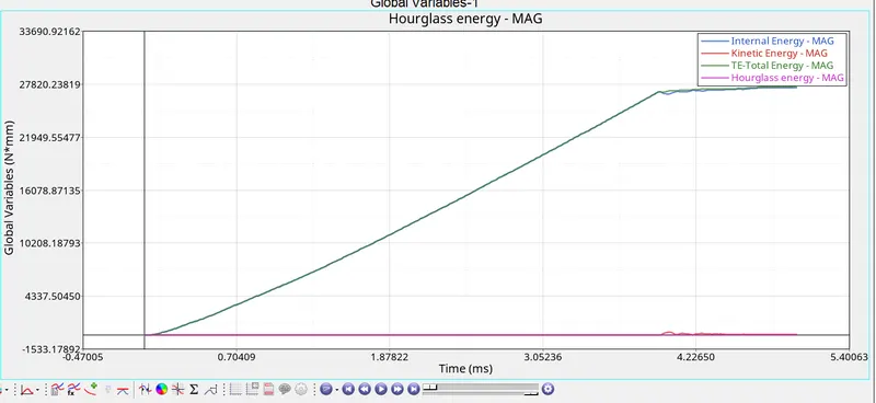
The internal energy varies almost linearly upto yield point and is constant after the yield point.
KINETIC ENERGY: As the plate is acting like a clamped component, the KE of the component = 0.
HOURGLASS ENERGY: Hourglass is taken care by the recommended properties and is zero in this case.
Total energy: Summation of all internal energy and kinetic energy. It is following the same trend as Internal energy as Kinetic energy is zero.
As the load is applied on the rupture plate, the plastic deformation takes place untill it reach the provided maximum strain and maximum stress.
As the plate reaches the max strain or max stress, the component fails and some elements gets removed and some elements remain in deformed shape due to plastic deformation.
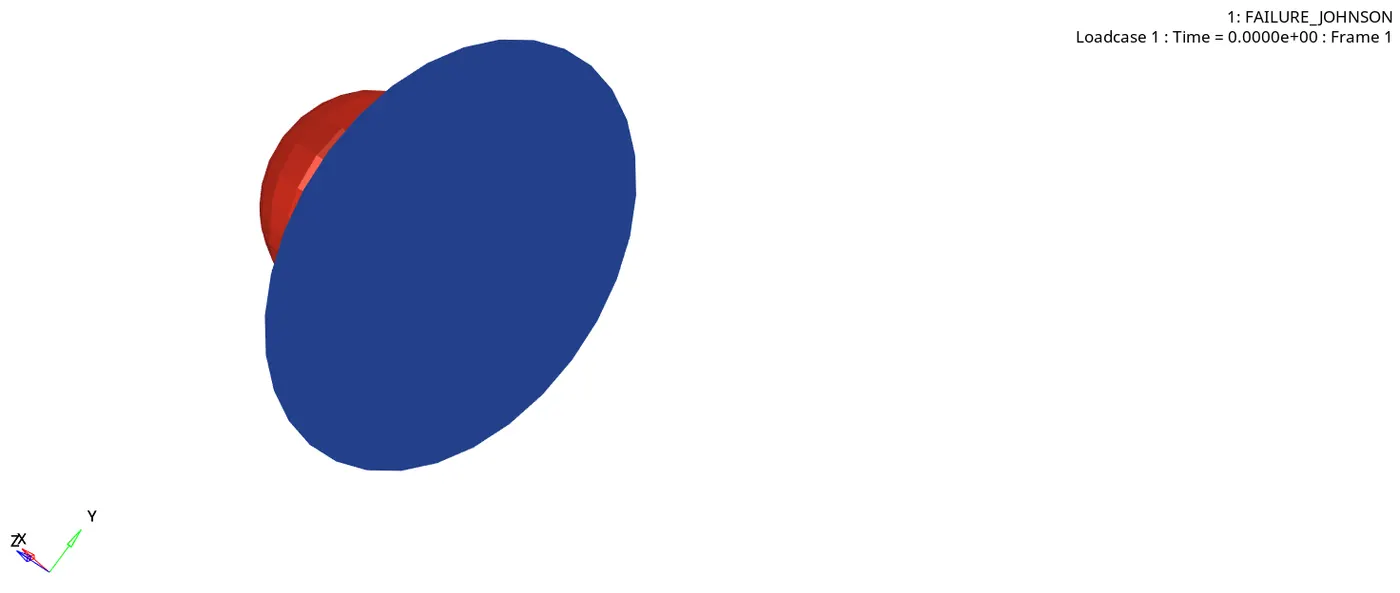
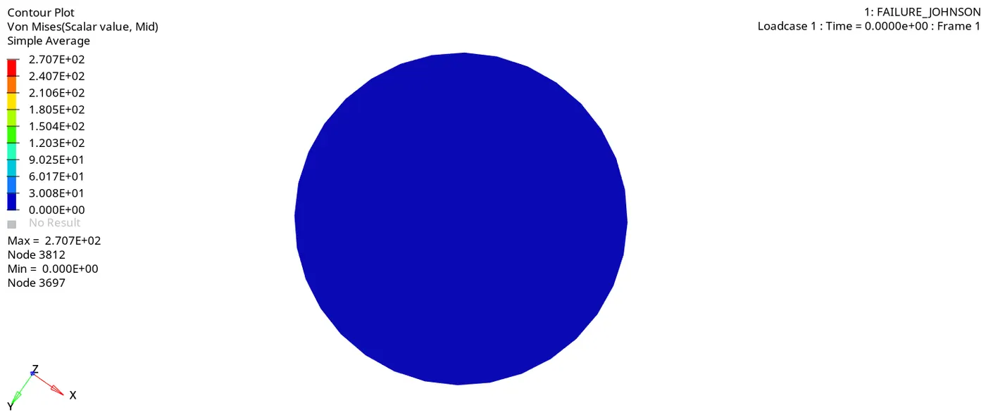
The maximum stress i.e., obtained is 270.7 MPA, the elements failing for max strain and max stress are blown away as shown in the figure.
CASE 4: Delete the value of EPS_p_max and run the simulation. (Named as Law2)
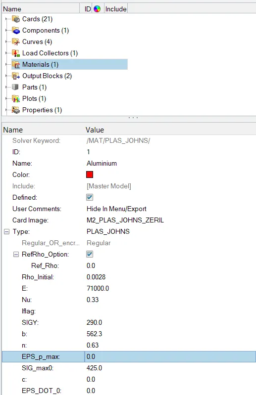
EPS_p_max is set to zero, we get infinite strain. The material fails as it reaches the maximum stress.
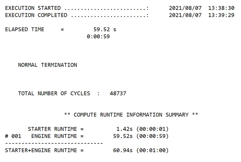
Total run time = 60.94 seconds.
Number of cycles = 48737.
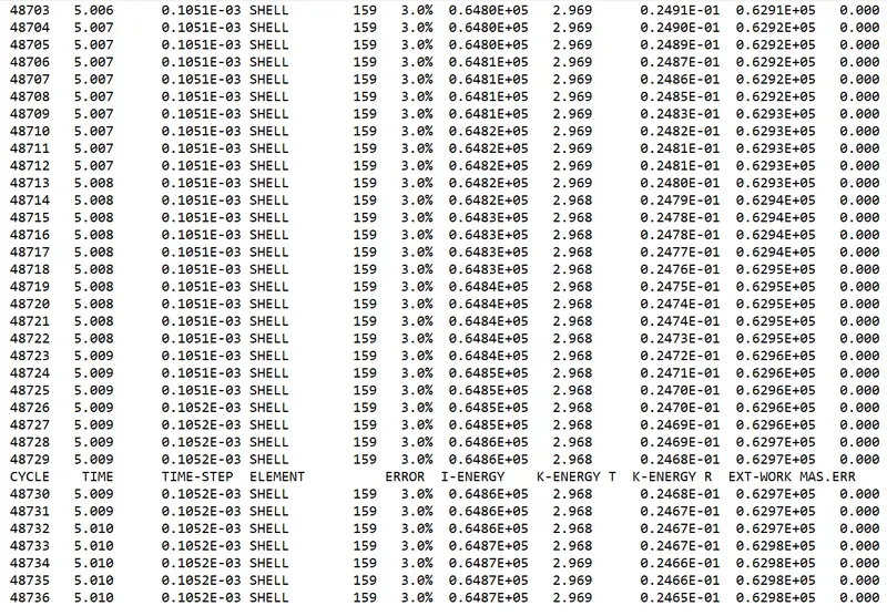
The energy error from the range of -15% to 5% is acceptable.
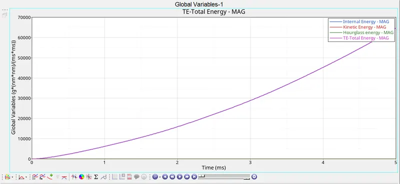
Internal Energy: The strain energy continues to increase at same rate even after crack is initiated. this result is undesirable and no material has infinite strain.
KINETIC ENERGY: As the plate is acting like a clamped component, the KE of the component = 0.
HOURGLASS ENERGY: Hourglass is taken care by the recommended properties and is zero in this case.
Total energy: Summation of all internal energy and kinetic energy. It is following the same trend as Internal energy as Kinetic energy is zero.
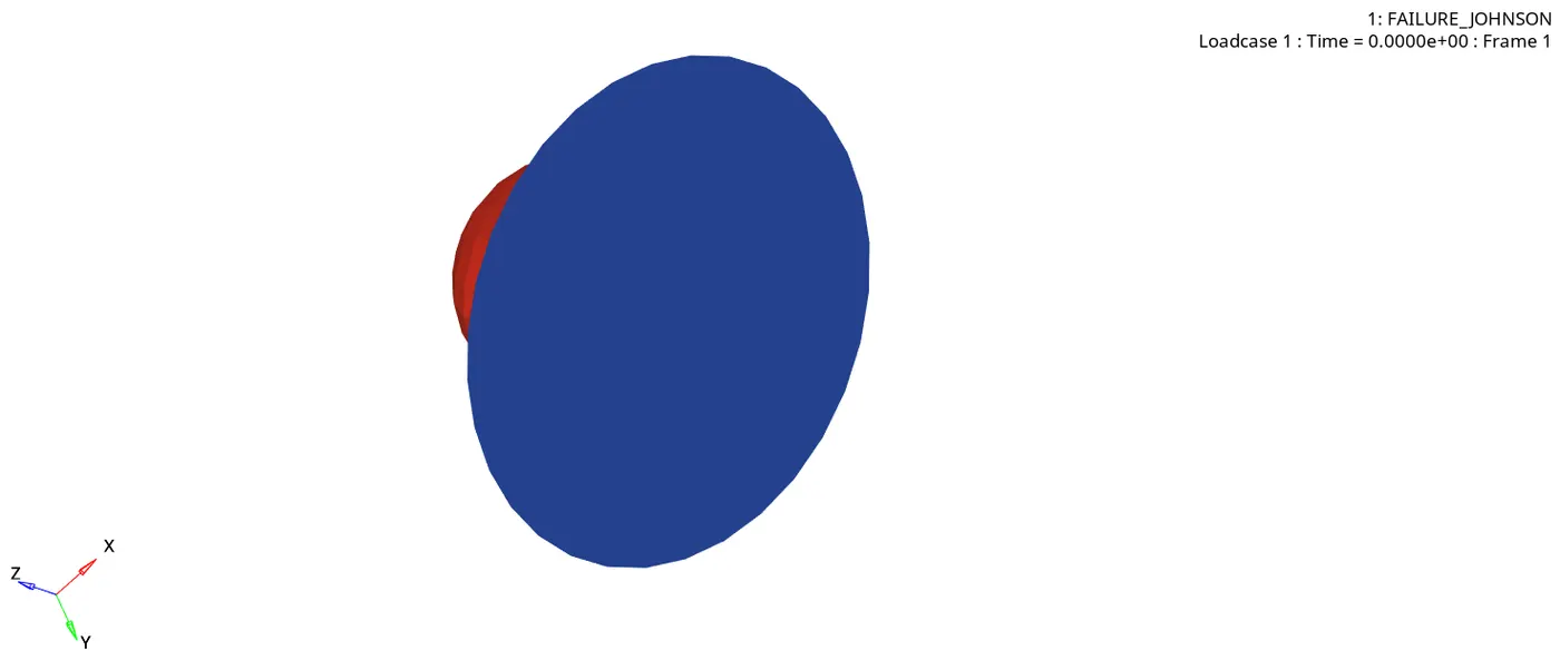
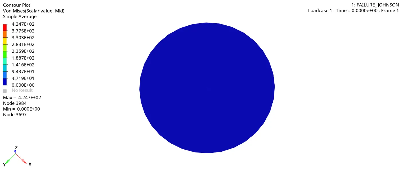
From the animation we can see that maximum stress = 424.7 MPA, tha failure criteria is based on maximum stress. The maximum stress provided is 425 MPA.
We can observe that only plastic deformation is taking place and some elements are coming out due to impact and almost maximum stress is attained.
CASE 5: Change the material card to MAT/LAW1 with same density, Poisson’s ratio and young’s modulus.(named as law1)
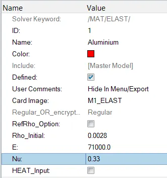
Material card is changed to law 1, initial density, youngs modulus, poissons's ratio has to be provided as given.
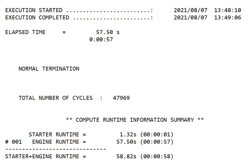
Total run time = 58.82 seconds.
Number of cycles = 47969.
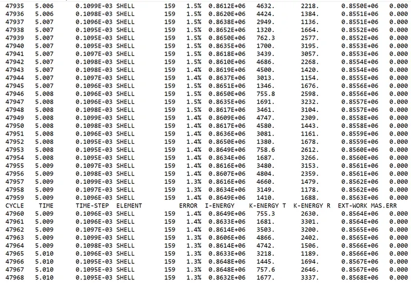
The energy error from the range of -15% to 5% is acceptable.
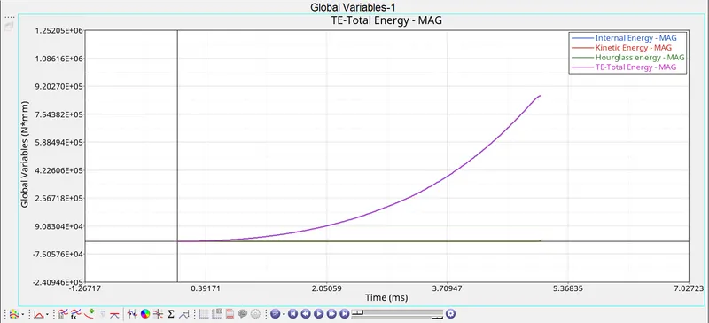
kinetic energy is zero as the plate is rigid, Hourglass energy is zero as recommended properties are used.
Internal energy: Increases parabolically w.r.t time, pure elastic deformation takes place.(practically not possible)
Total energy follows same trend as KE = 0.
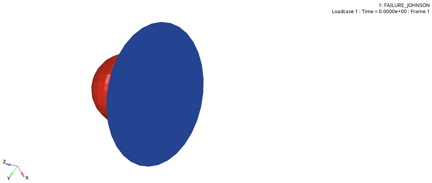
From the anime we can see that no crack is initiated and no elements are blown away.
Law 1 materials have infinite elasticity.
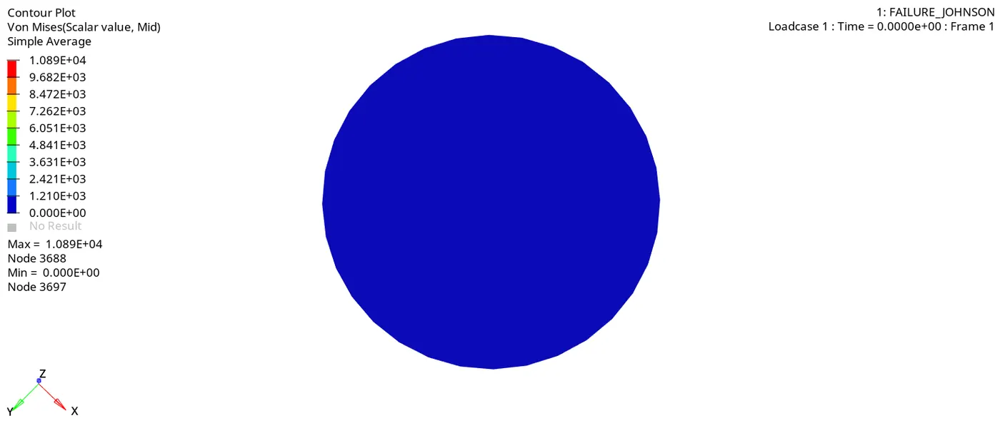
From the stress contour, we can see the maximum stress attained is 10890 MPA.
The stress is higher because the elements are elastically deformed to high extent and as no deformation is taking place, more stress is generated.
CASE 6: Change the material card to /MAT/LAW36(PLAS_TAB) and maintain the recommended shell properties, Provide the values in material card as given. (Named as law 36)
Change the material card to LAW_36, recommended shell properties are applied and The values in material card are provided.
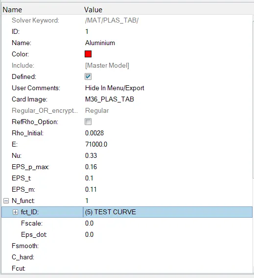
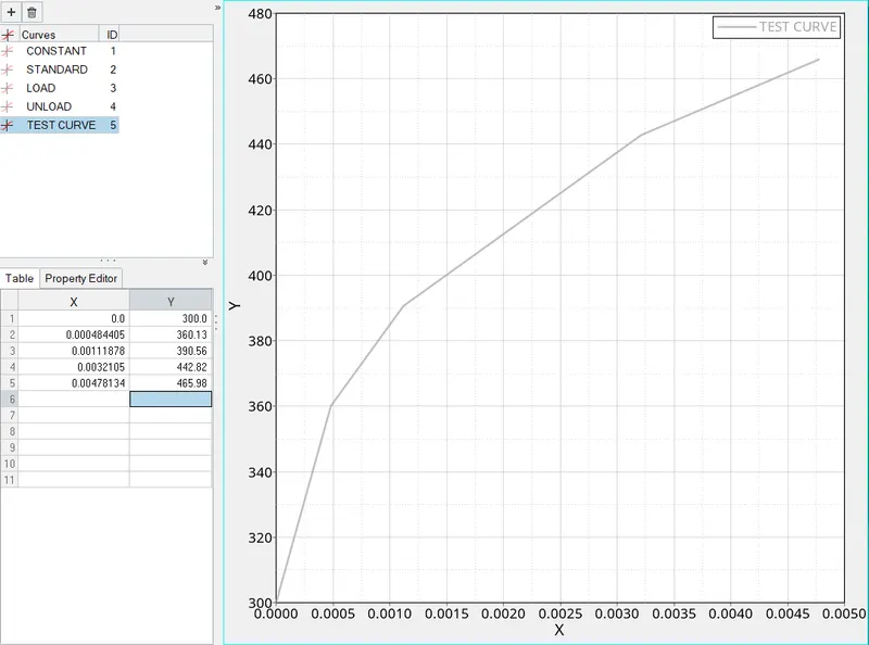
N _function is provided for the reference which are laboratory results. these results are taken into consideration when calculating for higher strain rates.
One can provide N number of graphs at different strain rates from the experimental results so that the general application results can be obtained by extrapolating the results for very high strain rates applications.
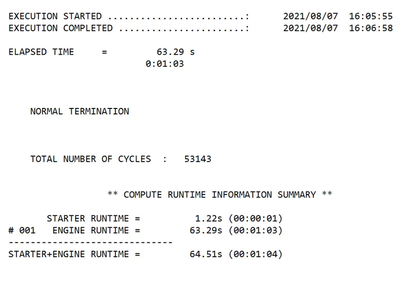
Total run time = 64.51 seconds.
Number of cycles = 53143
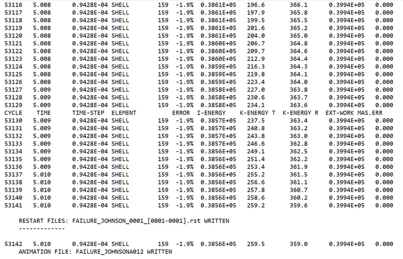
The energy error from the range of -15% to 5% is acceptable.
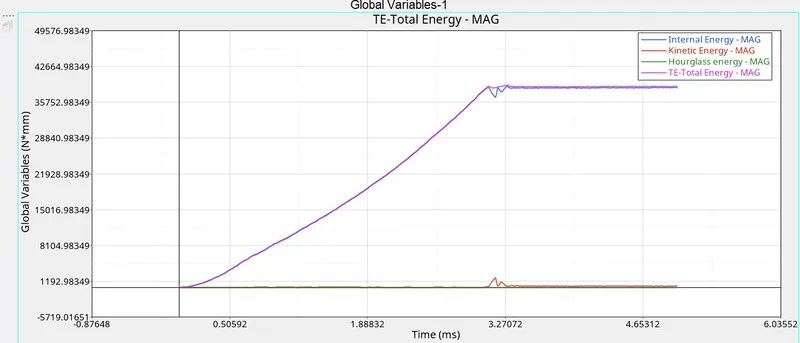
The internal energy varies almost linearly upto yield point and is constant after the yield point.
KINETIC ENERGY: As the plate is acting like a clamped component, the KE of the component = 0.
HOURGLASS ENERGY: Hourglass is taken care by the recommended properties and is zero in this case.
Total energy: Summation of all internal energy and kinetic energy. It is following the same trend as Internal energy as Kinetic energy is zero.
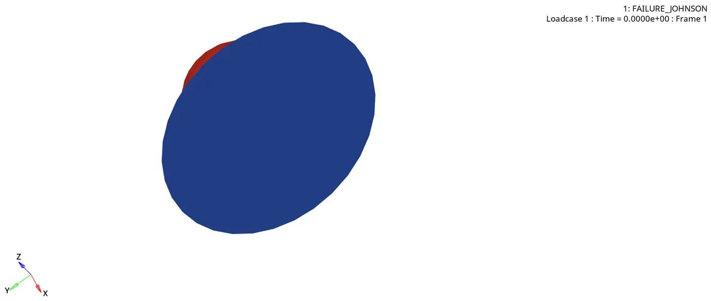
The element gets ruptered once it reaches the Failure strain, Stress reduction happens till σm but the strain occurs till σf and the failure occurs.
As the load is applied on the rupture plate, the plastic deformation takes place untill it reach the provided maximum strain and maximum stress.
As the plate reaches the max strain or max stress, the component fails and some elements gets removed and some elements remain in deformed shape due to plastic deformation.
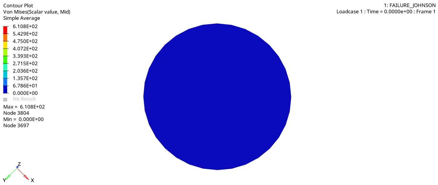
The maximum stress i.e., obtained is 610.8 MPA, the elements failing for max strain and max stress are blown away as shown in the figure.
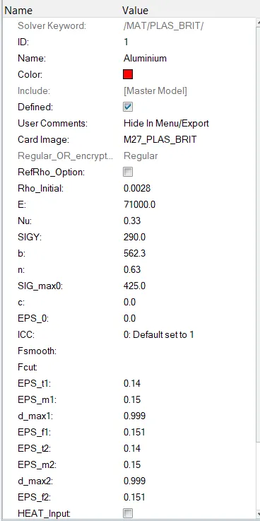
CASE 7: Use LAW27_0000 with card image asM27_PLAS_BRIT, and maintain the recommended shell properties, Provide the values in material card as given. (Named as law 27)
MATERIAL CARD:
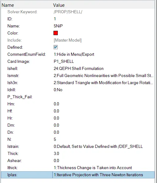
PROPERTY CARD:
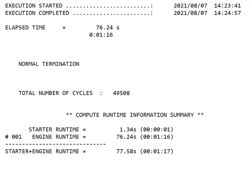
Total run time = 77.58 seconds.
Total number of cycles = 49508.
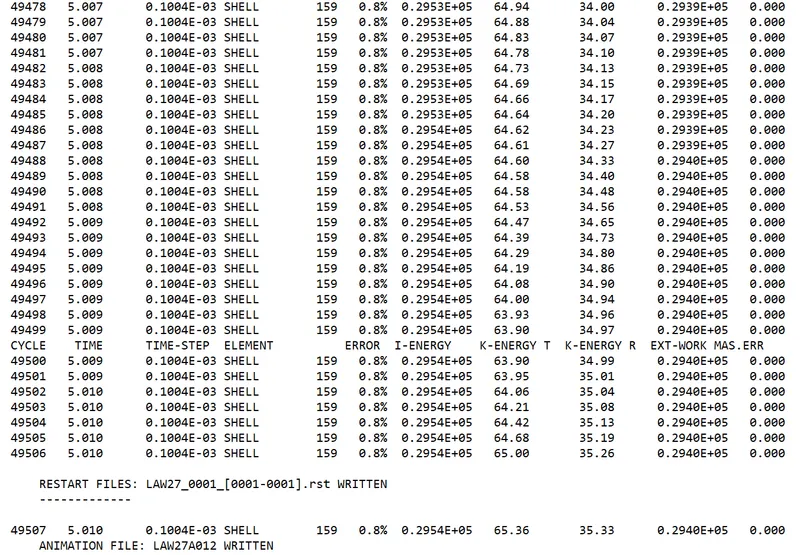
The energy error from the range of -15% to 5% is acceptable.
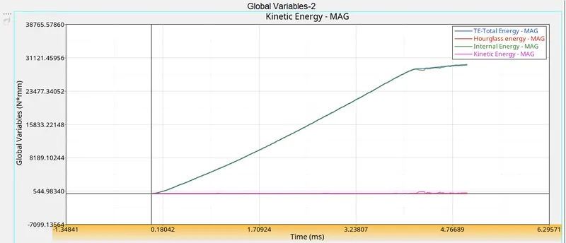
From the above graph we can see Internal energy is increasing till yield point and there after plastic deformation is very narrow(the nature of brittle materials).
KINETIC ENERGY: As the plate is acting like a clamped component, the KE of the component = 0.
HOURGLASS ENERGY: Hourglass is taken care by the recommended properties and is zero in this case.
Total energy: Summation of all internal energy and kinetic energy. It is following the same trend as Internal energy as Kinetic energy is zero.
Since brittle, the strength is very high leading to a higher yield point. At different stages of penetration, the elements are failing quickly and from resultant force gragh we can see there are sudden spike caused by deformations.
Plastic region is very narrow for brittle materials and the elements fails quickly due to lower strain rate. The failure occuring is due to maximum tensile strain. The element gets deleted as it reaches max. strain as shown above.
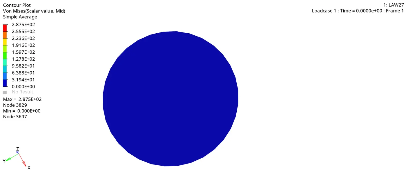
The max stress attained is 287.5 MPA and we can see the stress contour below.
RESULTS:
| RUN TIME | ENERGY ERROR % | MASS ERROR % | SIMULATION TIME SECS | |
| CASE 1 | 49380 | .8 | 0.00 | 61.35 |
| CASE 2 | 49217 | 4.1 | 0.00 | 60.41 |
| CASE 3 | 49408 | 0.8 | 0.00 | 61.09 |
| CASE 4 | 48737 | 3.0 | 0.00 | 60.94 |
| CASE 5 | 47969 | 1.3 | 0.00 | 58.82 |
| CASE 6 | 53143 | -1.9 | 0.00 | 64.51 |
| CASE 7 | 49508 | 0.8 | 0.00 | 77.58 |
CONCLUSION:
The selection of the material plays a huge role in automotive industry. For crash analysis we use materials which deforms plastically and absorb most of the energy thereby decresing the effect of jerk to occupants inside.
The higher stiff materials, doesnot undergo larger deformations and transfers the load to neighbouring components causing greater jerk to occupants.
The materials which fail under stress by dissipating absorbed energy in other kinds of energy like sound energy, heat energy is most suitable, as it reduces the impact of collision.
From the above all cases, we can say case-6 i.e., LAW36 is more suitable and compatible for real time applications.
We input the lab data at different strain rates as user defined functions and extrapolate the results for higher strain rate.