Assignment 4-RADIOSS Material Laws Challenge
AIM:-
To apply differet material types to the simulation model and compare the behaviour of the material with differnt element and failure formulations.
PROCEDURE:
CASE:-
Import the provided 0000.rad into the hypermesh workspace and change the properties to the recommanded properties for shell elements.
save the model and run the simulation without changing the failure card.
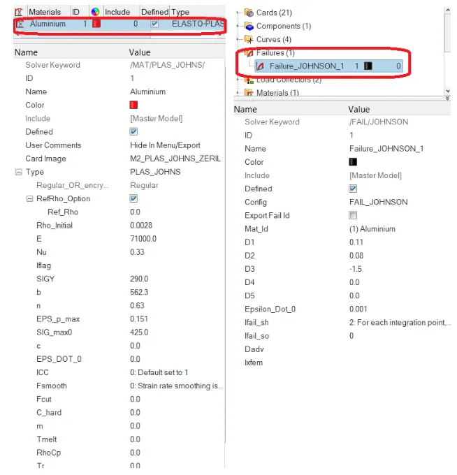
Material and failure cards for the simulation
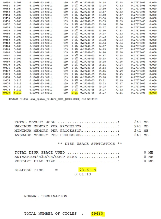
0001.out at the end of the simulation.
From the above image the total number of cycle at the end of 5ms is 49480 and energy error is 0.2% which indicates that the simulation is stable and there is no energy create in the simulation and mass error is 0.0.
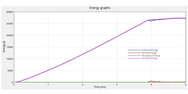
energy graph:-
The above graph shown the interanl kinetic, hourglass and total energy in the simulation. from the graph it can be seen that their is no hourglass energy produced in the simulation the internal energy increase as time increase this is because of element absorbing the force acting on them.
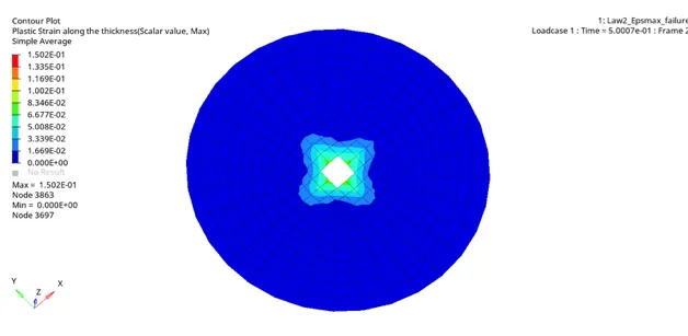
plastic strain contour graph:-
in the above image we can see that the elemnt are delete when they reach 15% palstic strain after the yield stress value.
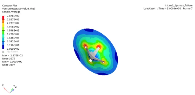
it can be seen that the element are being deleted when they reach the 15.1% plastic strain arear the yield stress of 290mpa, the maximum straess in the simulation is 287.6mpa.
element brack becaue the johnson cook failure criteria model is applied to the simulation model which considerd both tensile and compresive failure into account, when the element plastic starin reached eps_p_max value they are delete from the simulation which is seen in the model above.
---------------------------
CASE 2:-
change the failure card as shown below.
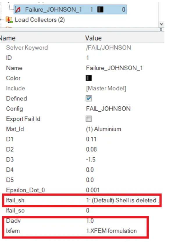
edit failuere card:-
here ifail_sh is shell failure flag set to 1 which will ganerated crack in the shell element when ixfem is set to 1, dadv is the criterion for the crack advancement.
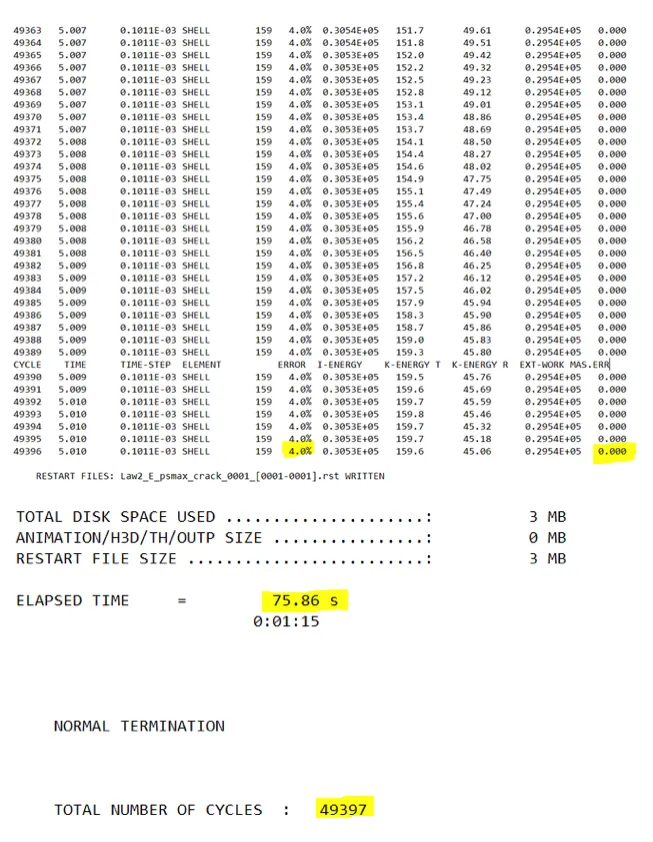
image above show the energy error, amss error, number of cycle and the time.
energy error is +4% which is acceptable result, the simulation time taken is 75.86s which is higher than the previous simulation.
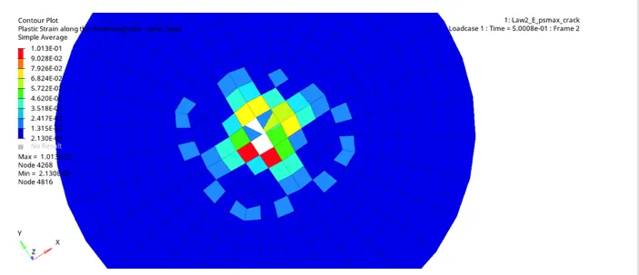
platic strain contour plat.
image above shown element being cracked at the centre before getting deleted.
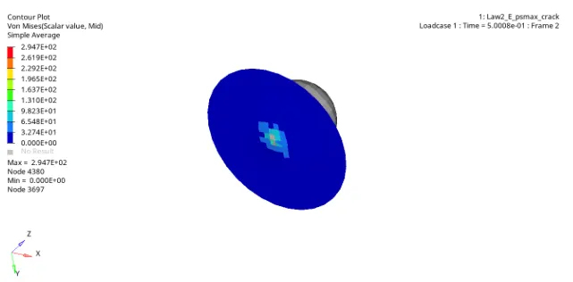
The maximum stress in the simulation is 294.7mpa ehich is higher than the previous simulation. crack developemant can be seen in the simulation.
since the crack advancemant is set the maximum value of 1 and ifail_sh is activated for shell element, we can see the crack being generated in the simulation.
CASE 3:-
delet the failure card from the simulation and run the simulation.
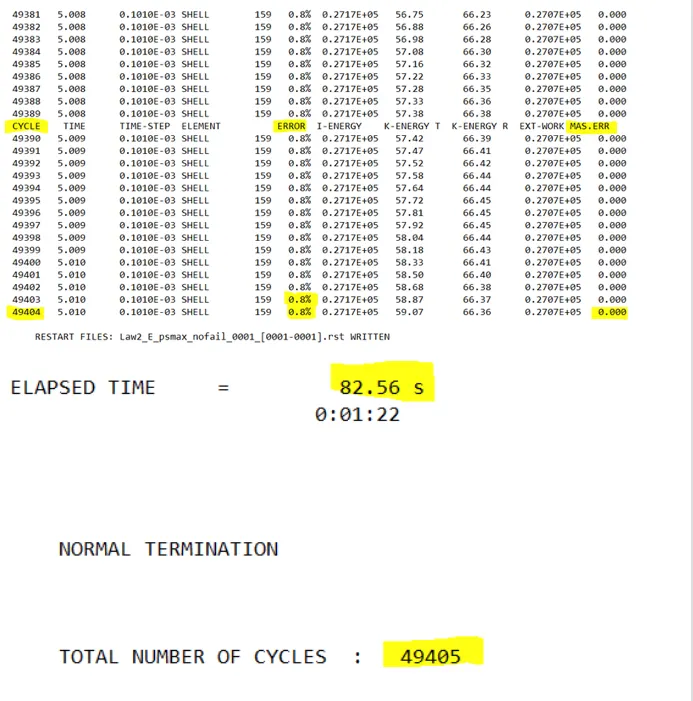
energy error is at 0.8% which is less than 15%, hence the result is acceptable time elapsed for this case is more than the previous two simulation.
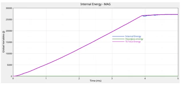
hourglass energy in the simulation is zero, this is due to QEPH24 elemnt formulation, the internal energy in the model increae with time similar to both the previous simulations
hourglass energy and kinetic energy in the system are
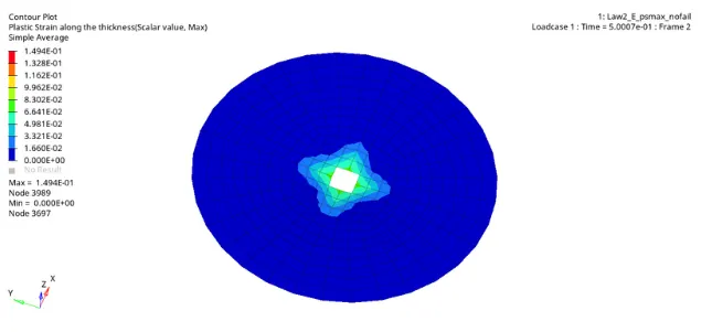
plastic strain contour.
the elements are deleted in this simulation.
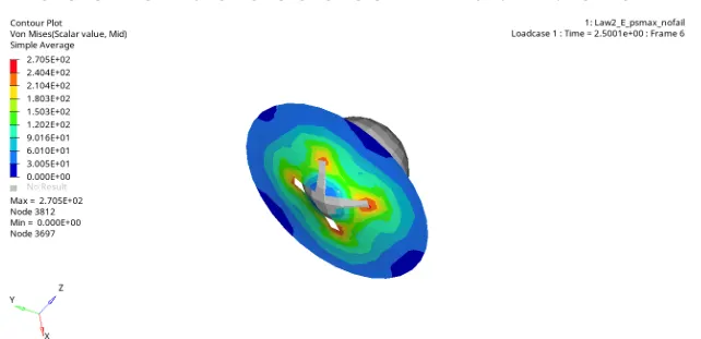
The maximum stress in the model is 270.5mpa, and the3ir is no crack observed in the simulation.
CASE 4;-
Runninh the model with zero EPS_P_max value.
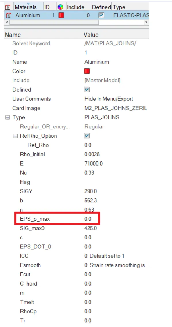
material card image.
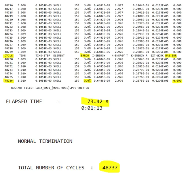
energy and mass error are in acceptable range.
time for the simulation is less than other three simulations.
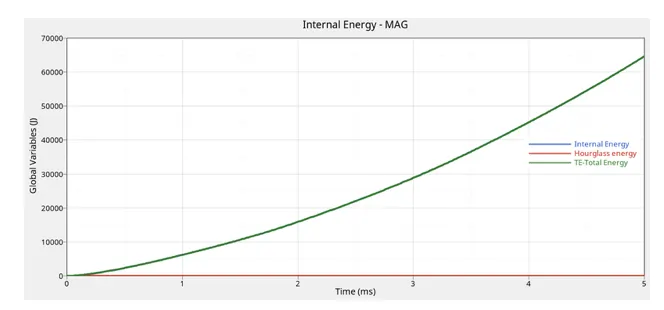
The above image shown that their is no hourglass energy generated in the simulation and internal energy and total energy of the simulation model intecepts eachother and increase with time.
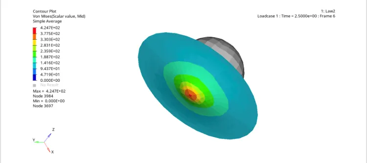
In this simulation model the elemnt do not fail as the their is no failure criteria applied to the model, and eps_p_max (afilure plastic strain) value is deleted which sets it to the default value of 10^30, and the maximum stress value is set to 425mpa due to whic the maximum stresses in the model seen to be 424.7mpa, and their are no element deleted in the model.
CASE 5:-
Charging the law 2 (elasto-platic material) to law 1 (linear elastic material) with same value of E (younga modulus), density and poissons ratio.
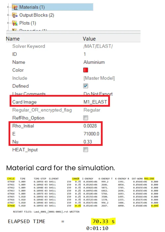
energy error and mass error are in the acceptable range and time elapsed for the simulation is 70.33s which is least compaered to previous four cases.
four cases.
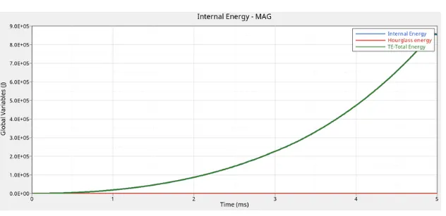
no hourglass energy generated in the simulation and internal energy and total energy of the simulation model intecepts eachother and increase exponentially with time.
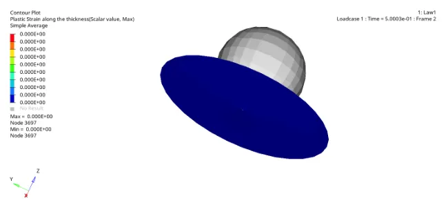
Since the material law applied is liner elastic , their is no plastic region in the material hence no element fail and no platic strain is recorded in the simulation.
The material has no maximum stress define and the stress strain relation is linear, hence is no failure of the element.
CASE 6:-
Change the material vard to law 27 (elato-platic - cook material model with an orthotropic brittle failure model)
this law combine johnson cook material with the brittle failure method this law is applicable only for shell elements.
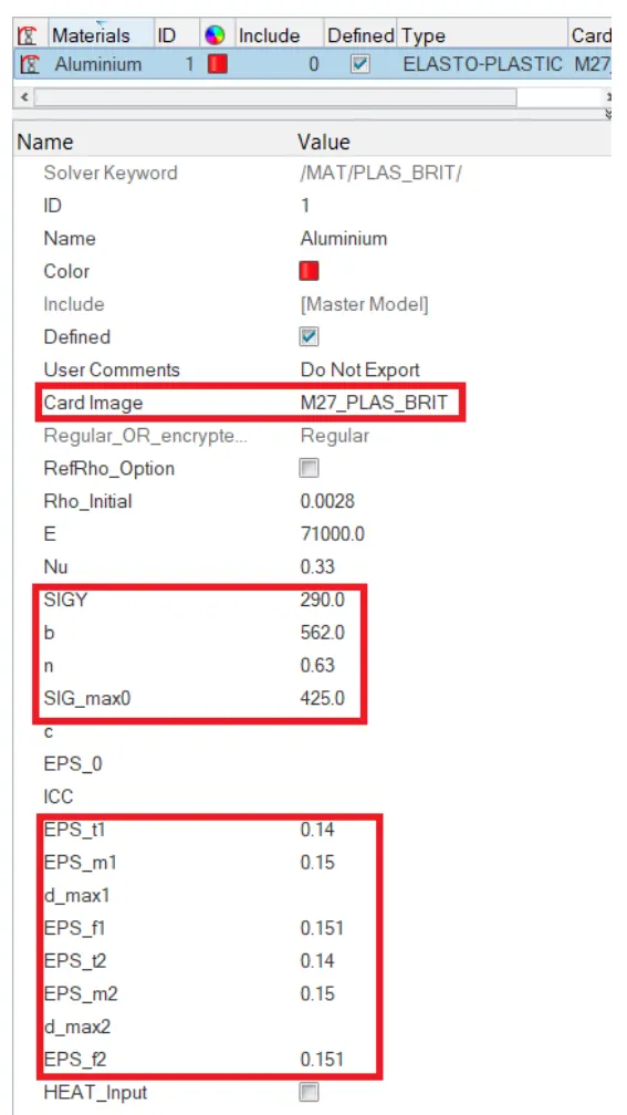
material card for LAW 27.
where, EPS_T1 tensile failure strain at which starts to reduce in the principle strain direction 1.
EPS_m1 is maximum tensile failure strain in principle strain direction 1 at which the stress in the element is set to a value dependent on dmax1
EPS-f1 is maximum tensile dtrain for element deletion in principle strain direction 1
dmax1 is maximum damage factor in principle strain 1 which is at default value of 0.999
EPS_T2, EPS_m2 and EPS_f2 are for direction 2.
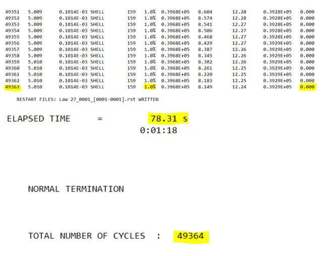
energy error and error value are in acceptable range for the simulation, time for elapsed for the simulation is 78.31s ehich is second heighest after case 3.
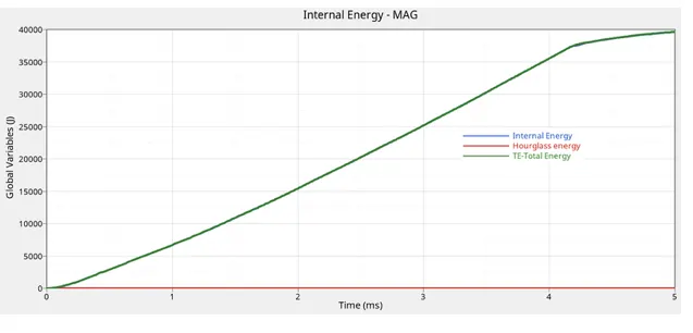
Their is no hourglass energy in the simulation model, the internal energy and total energy increase with time and then tends to flaten after 4ms as seen in the image above.
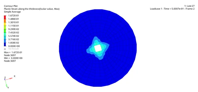
element are delete in the simulation due to EPS_t, EPS_m and EPS_f values.
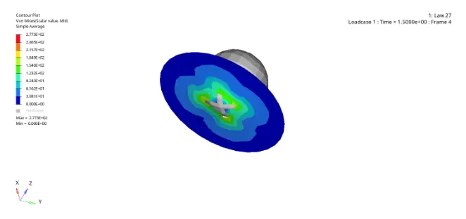
The maxiumu stess developed in the simulation is at 277.3 mpa, which is below the plasticity yield stress value of 290mpa.
the material breackes after the vracks reach the end of material boundary as seen in the simulation image.
CASE 7:-
Law 36 which is a isotropic-plastic material using user-defined functions (curve).
create a curve with to apply in the material model N_funct.
Material card selection and curve selection.
N_funct is number of function which can be between 1 and 100 depending on the requireement of the simulation.
Fscale default value is 1.
energy error and mass error are in acceptable range for the simulation, and time elapsed is 76.07s.
Their is no hourglass energy generated in the simualtion model, the internal energy increase with time as seen in the image.
once the EPS_p (plastic strain) reaches EPS_P_max, in one integration point the element is deleted.
case
material law
simulation name
energy error (%)
simulation time (s)
number of cycles
maximum stress value (Mpa)
element behaviour
1
law (jognson-cook model)
EPS_MAX_Failure
0.2
73.61
49480
287.6
deleted
2
law 2 (johnson-cook model)
EPS_MAX_failure_creack
4
75.86
49397
294.7
crack first then deleted
3
law 2 (johnson-cook model)
EPS_MAX_nofail
0.8
82.56
49405
270.5
deleted
4
law 2 (johnso-ccok model)
law 2
3
73.42
48737
424.7
preserved
5
law 1(linear elastic material)
law 1
0.3
70.33
47969
10860
preserved
6
law 27 (brittle failure model)
law 27
1
78.31
49364
277.3
deleted
7
law 36 (elasto-plastic material)
law 36
0.8
76.07
52237
1286
deleted
Stree developd in different material formulation.
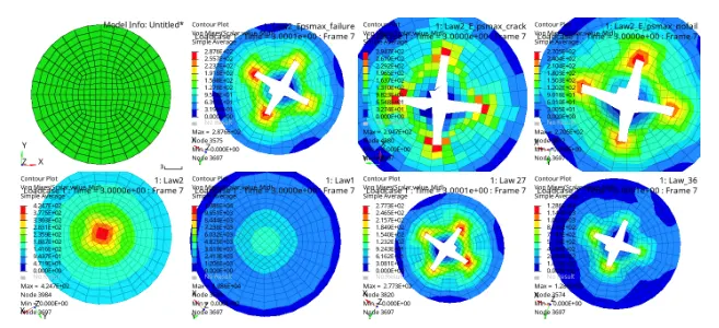
based on the stresses developed in the material, and given material data for aluminum with yield stress of 290 mpa and maximum stress of 425mpa, case 2 presents the on-field scenario comparied to rest of the cases.
CONCULSION:-
comparison between different material cards and failure cards has been carried out by applying them to the given simulation model. element behaviour and stress development has been discussed based on the observation of results : case 2 presents the best on-field scenario in the simulation.