Assignment 3-2D Element Formulation Challenge
AIM: Run the simulation Compare results with base simulation and improved shell element properties.
1.Change the number of animation steps during simulation to a minimum of 25 and maximum of 60.
3. Run the base simulation without any modification to element properties.
4. At the end of the simulation, do the energy error and mass error checks and determine whether results would be acceptable.
5. If acceptable, Plot rigid wall forces, internal energy, hourglass energy, contact energy, total energy of the simulations.
6. Change all the shell elements properties to recommended properties, save this as separate, rad files and run the simulation.
8. Create a brief report comparing all the results from steps 5 and 6 for both simulations.
9. Comment whether there is any change in the results and why there is any change in the result.
comment on the below parameters
|
Ishell =24 |
QEPH 4 nodes shells are best combination of cost and accuracy. | |
|
Ismstr=2 |
Full geometric nonlinearities (default)with possible small strain formulation activation in RADIOSS Engine. | |
|
Ish3n=2 |
Standard 3 noded shell (C0)with modification for large rotation(default) |
|
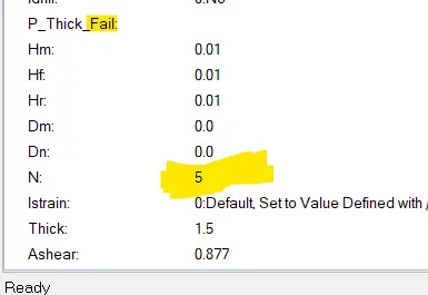
| N=5 | Number of integration points set to 5 for accuracy bending. | |
|
Ithick=1 |
Thickness change is taken into account for accuracy. |
|
|
Iplas=1 |
Iterative plasticity for good accuracy. |
introduction about element formulation
The /PROP/SHELL property card describes the shell property set. The major parameters to be activated in a PSHELL card are Ishell, N and Thickness.
Ishell defines various shell element formulation flag. Ishell=24 (QEPH) formulation is recommended for structural analysis.
QEPH shells are more accurate for elastic or elasto-plastic loads, whatever the loading type - quasi-static or dynamic, but they are not recommended with orthotropic material laws.
N defines number of integration points through the thickness. N=5 is always recommended. If only one integration point is used, only membrane behavior will be obtained. In case of a plastic behavior, the bending moments are not integrated exactly. Using more integration points, the solution becomes more accurate; so it is recommended to use five integration points. And these shell parameters reduces hourglass.
2D shell element formulation
Types of reduced and ful integrated 3 and 4 noded shell elements
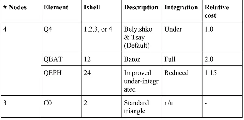
hell elements : Reduced integration scheme
1:They have 1 integration point at the surface of the element usually the integration point lies on center
2:widely used in programs with the explicit time integration ,applied in crashworthyness studies
3:takes less time compared to 4 point integration schemes
4:Major adventage is that it controls/stablizes the hourglass mode
Hourglass
It is a weried mode of deformation that occurs in under integrated shell elements (Ishell=1,2,2,4) where stress are not produced .Therefore when stresses are not produced it reduces accuracy and true response of the structure.this leads to inaccurate strain and displacement results with unrealistic deformation.
when do we say that hourglass is produced
in an under integrated element, displacement and forces exists at each node of the element, if the summation of all these forces and displacement provides zero stress and strain on the integration point of the element, then the element fails to calculate stifness for the mode of deformation.when there is no stiffness calculation the deformation happens in a weried manner.thus the element has entered into hourglass mode
In other words hourglass is a deformation that is noticed when when an element is deformed due to applied load.the strain energy due to deformation is not recorded for that element we can say this is called zero energy deformation mode where an element is seen deformed
.it can be seen in the post processing stage where the element have zig zag shape .
Module1
intially we are going to import solver deck model that is nothing but RUN_FIRST_0000.rad file import this file into the hypermesh gui and check you have selected the radioss as solver.
once the model is imported into the hypermesh gui you will see the as shown below
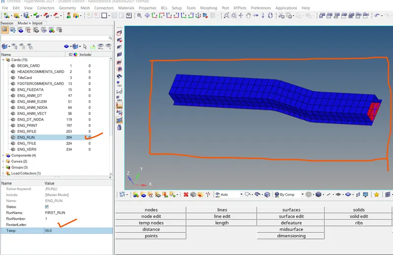
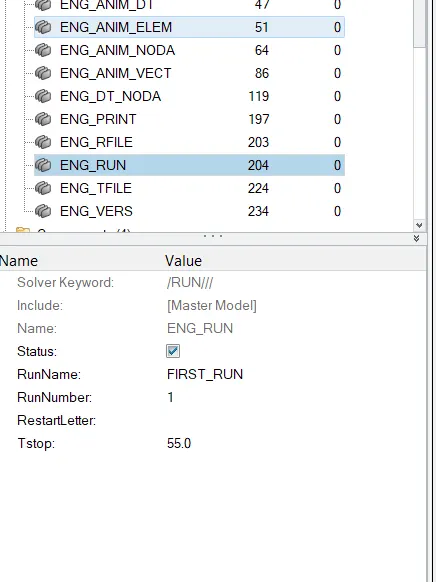
In the above model we have to change the run time (Tstop) =55milli-sec
click on cards there are almost 15 cards and we have to select the ENGINE_RUN card to change the run time ,once you click on engine run a window will open just below the model browser set Tstop =55.0ms
2:we have Change the number of animation steps during simulation to a minimum of 25 and maximum of 60.
time to complete one animation =55.0ms
in order to get the one animation what will be the time step in ms
T freq=time step /no of animation step
= 55/55
Tfreq=1
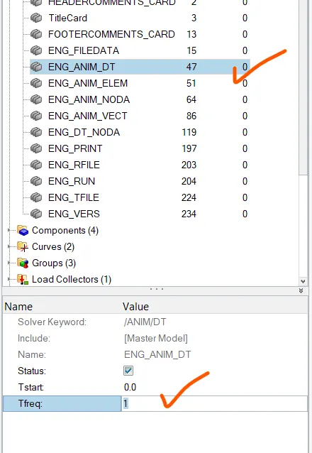
now we need to change Tfreq in the ENG_ANIM_DT
click on ENG_ANIM_DT and set the value of Tfreq=1
in our first case we need to run the simulation on defaulted parameters
click on analysis from the pannel >select the radioss as solver

once you click on radioss it will take you to other window

in the above snap we have to keep all the parameters as defaulted and click on radioss .once we click on the radioss the simulation is going to run and takes few minutes to complete the job once the job gets completed a window will open shows that the job is complete
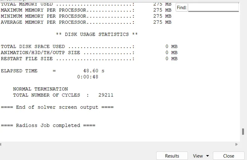
to check the animation we have to click on results it will take us directly to hyperview .in the hyperview we need to check h3D file
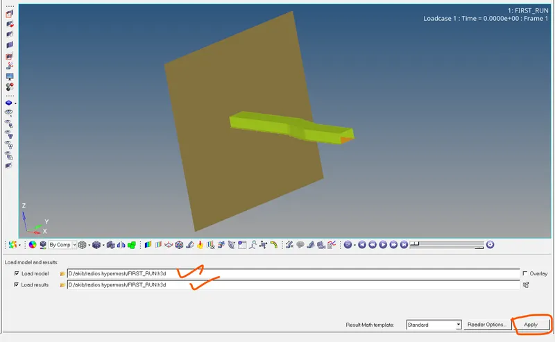
to see the animation we need to click on apply and an error message will popup we have to click on yes
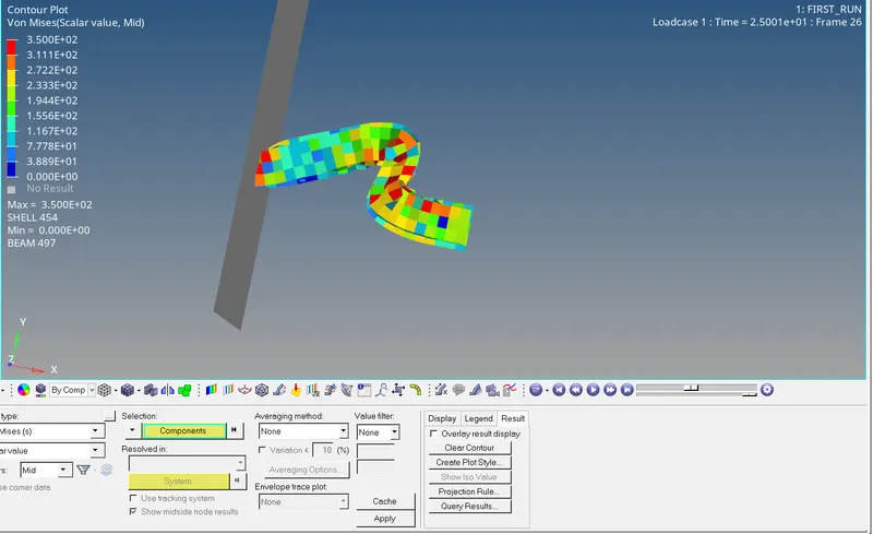
from the below snap it shows von Mises stress in the component
from the contour plot we can visualise the maximum and minimum von mises stress occuring in the component
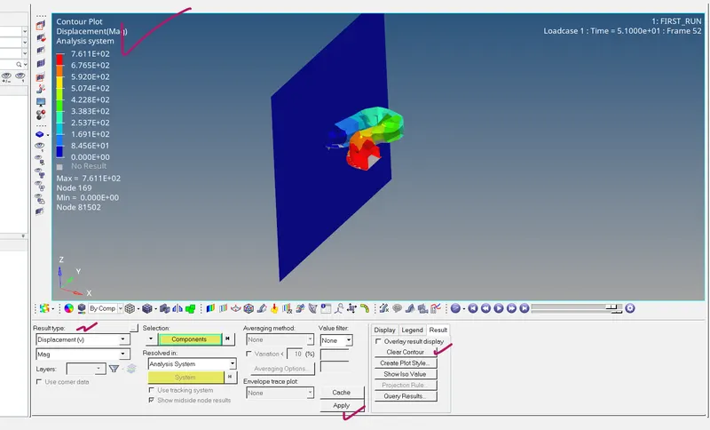
we can also visualise displacement ,velocity hourglass energy etc for that we need to click on result type in hyperview select the displacement /hourglass energy/velocity >click on apply and clear the contour
the results are shown below the von mises stress contour plot
Displacement contour
at the end of the simulation we need to check energy error and mass error and determine whether results would be acceptable.
we need to open the RUN_FIRST_0000.OUT to check the errors
from the results below it is clearly visible that energy error starts at 0.0% while mass error strats from the value 0.1659E-03
The energy errors goes upto -10.3% and is acceptable
while for the mass error it remains constant and at the end of simulation it was recorded 0.1659E-03

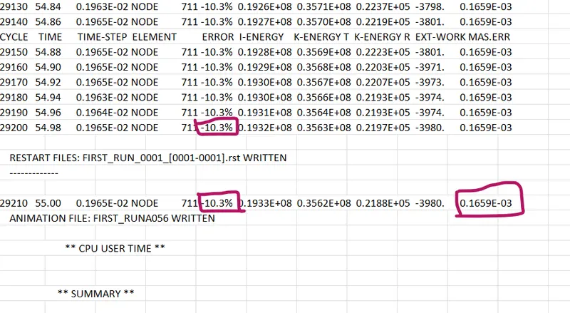
the acceptable energy tolerance value lies between -15% to +5%
If the above results are acceptable, Plot rigid wall forces, internal energy, hourglass energy, contact energy, total energy of the simulations.
since the energy and mass error is acceptable we need to plot mentioned below
grid wall forces
internal energy
hourglass energy
contact energy
total energy
to plot the above graphs we need to click on hypergraph 2D>click on client sector>click on hypergraph 2D
For data file we need to select the T01 file in the data file ,this is the result file generated by radioss solver we need this as an input data file for hypergraph2D
once the file is selected the next step is to click apply
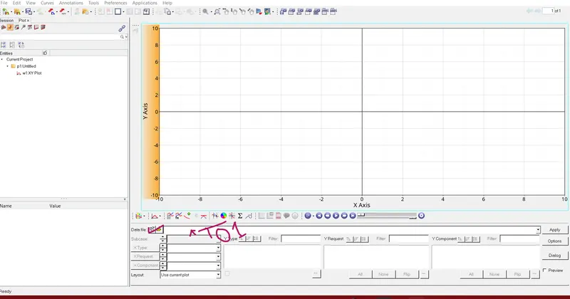
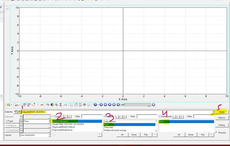
once you click apply a window will open shown in the below snap there are many variables listed
we need to select the global variables in y type and in y request we need to select those variables that has been asked from the challenge those are nothing but internal energy, kinetic energy ,mass,hourglass energy,Total energy
to select these variables >hold on control key (ctrl) and left click on the variables listed above
we need magnitude of all the variables listed above ,for that we need to select in y cpomponent as MAG
now click on apply and results will be shown in 2d form
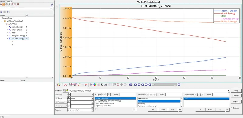
from the above snape it is clearly shown that kinetic energy and total energy are falling while the hourglass and internal energy goes on increasing
kinetic energy =0.5mv^2 (increasing velocity means increasing kinetic energy)
at beginning velocity is applied to the rail component and is maximum at the start of simulation and it decreases wrt time because of deformation within the rail component .due to the deformation within the rail component the velocity decreases and this in turn decrease the kinetic energy thats why at intial its high and after certain time it gradually decreases .
internal energy : at beginning there is no displacement in the rail component thus the internal energy starts from 0.when the acceleration is applied displacement occurs in the component and internal energy increases gradually.
Hourglasss energy:
since we have run the simulation on defaulted parameters and did not use the element formulation methods like reduced and full integration to reduce the hourglass energy this means there will be more element deformation and at the same time strain is not recorded .which depcits that ,the element undergo hourglass effect.to avoide hourglass effect ,artifical energy is required thats is what we called hourglass energy.from the above plot the it is clearly shown that sufficient hourglass energy is needed to balance the element deformation.
Total energy: as the hourglass energy increases that means more energy is not recorded in this case thats why the total energy falls
Plot rigid wall forces:
to plot rigid wall forces we need to create a new plot
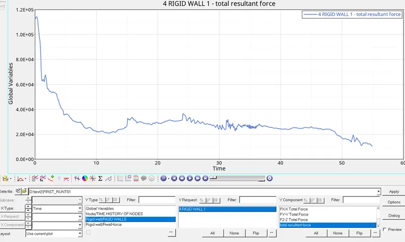
in y type select rifid wall/Rwall forces>in y request select 4 rigid wall 1>in y component select total resultant forces
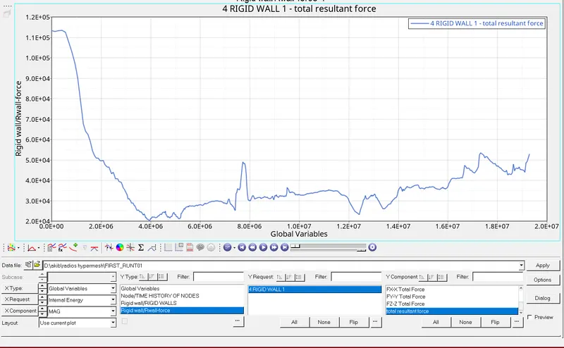
the above plot shows R wall forces rigid wall forces and it is clearly visible that the curve is non linear which is due to the varation of force exerted by rail component on the wall .the impact is high at the start and decreases suddenly afterwords
MODULE2
Change all the shell elements properties to recommended properties, save this as separate, rad files and run the simulation.
the procedure is same just like the above case
we need to change some properties
the simulation starts from 25ms and set Tfreq=1
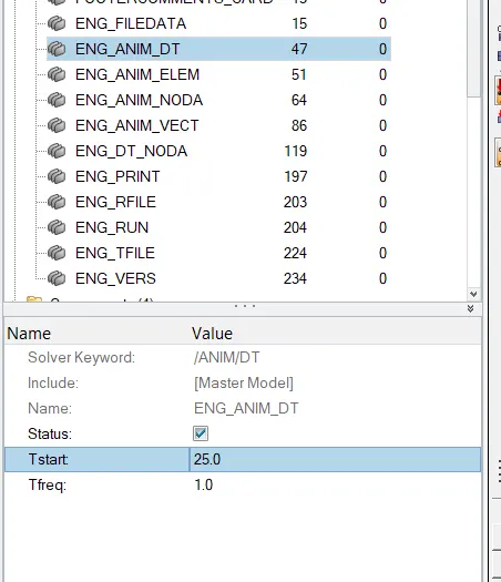
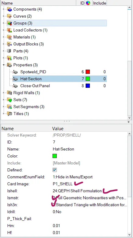
in the property tab below click on hat section and change ishell=24
ismstr =ful geometric non linearties
ish3n=standard trangle with modification
set Tstop in the ENG_RUN=55ms
N=5 (no of integration points alomng thickness
once all the required parameters has been changed you will need to save this file in a different folder so that you can easily findout the file
set options =-nt 4 and hit radioss
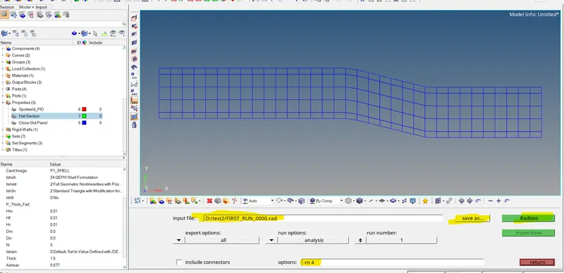
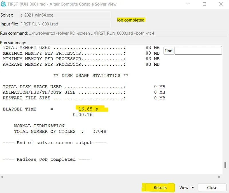
once you click on radioss a consol window will open that will compute all the results and it will take seconds to calculate all the results
in order to view the results we need to click on results in the console window shown below
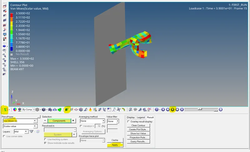
once you click on results it will take us directly to hyperview window where we can analyse the sterss ,displacement ,starin etc
click on client selector >select hyperview >click on contour
in result type select first von Mises and play the animation
contour plot of von mises
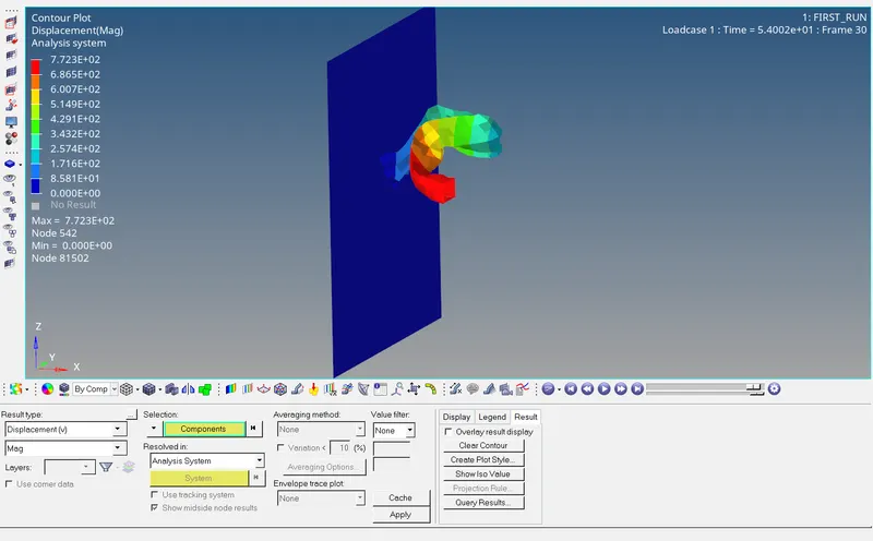
similarally we can visualise the displacement results
the next step is to check the energy error and mass error check in the FIRST_RUN_0001.out file
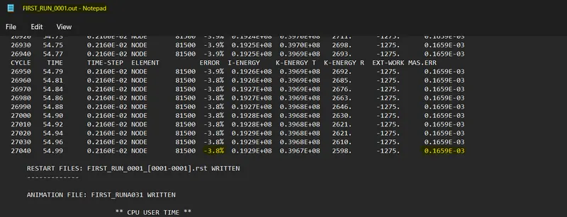
from the above snape it is clearly shown that energy error in this case is 3.8% and mass error remains constant throughout the simulation
the acceptable energy tolerance value lies between -15% to +5%
If the above results are acceptable, Plot rigid wall forces, internal energy, hourglass energy, contact energy, total energy of the simulations.
since the energy and mass error is acceptable we need to plot mentioned below
grid wall forces
internal energy
hourglass energy
contact energy
total energy
to plot the above graphs we need to click on hypergraph 2D>click on client sector>click on hypergraph 2D
For data file we need to select the T01 file in the data file ,this is the result file generated by radioss solver we need this as an input data file for hypergraph2D
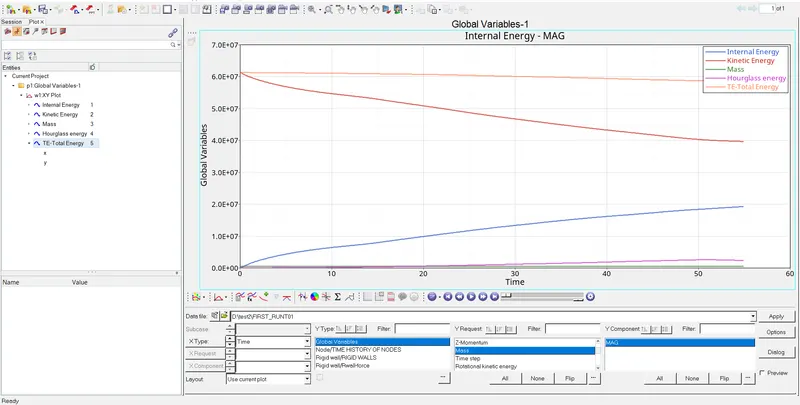
in this case the hourglass energy has been significantely reduced in this case we have use some element folmulation methods to reduce the hourglass energy when the hourglass energy decreases the effect will be seen in the total energy that didnot get reduced as in the previous case
now we are going to plot rwall forces
 \
\
Create a brief report comparing all the results
case 1 case 2
maximum energy error -10.3% -3.8%
K.E max obtained 0.3563E+08 0.3967E+08
INTERNAL ENERGY 0.1933E+08 0.1929E+08
HOURGLASS ENERGY REQUIRE HIGH LESS
RESULTS less accurate accurate