Assignment 3-2D Element Formulation Challenge
2D Element formulation
Objective:
Comparison of results with base simulation and improved shell element properties.
CASE 1:
PROCEDURE:
- First import the model using the solver deck option and choose 0000.rad file.
- Now change the engine run time to 55ms under the engine cards.
- Now go to analysis and click on radioss and give the number of threads as 4 and run the simulation.
- Once the simulation is done open the h3d file in hyperview and use the split screen option to open another window with hypergrpaphs 2D.
- now chose the T01 file and select the global variables to input the required energy plots.
- For rigid wall forces chose the rigid wall option and select the total resultant force.
IMAGES OF GRAPHS WITH MODEL:
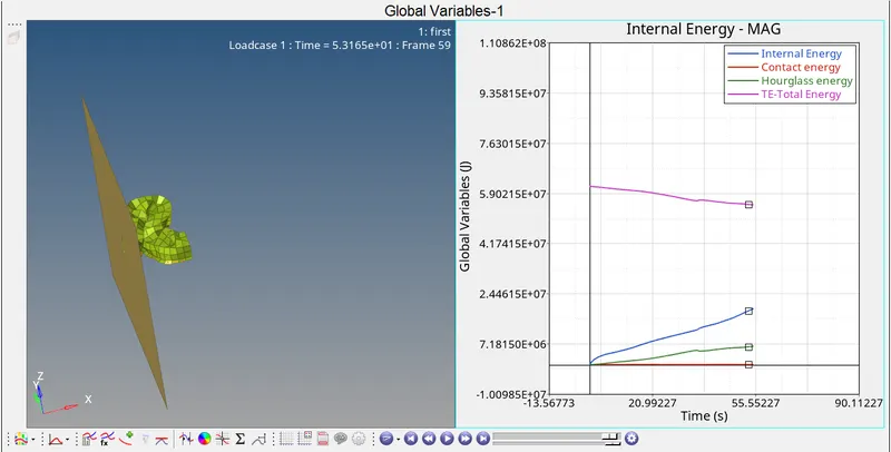
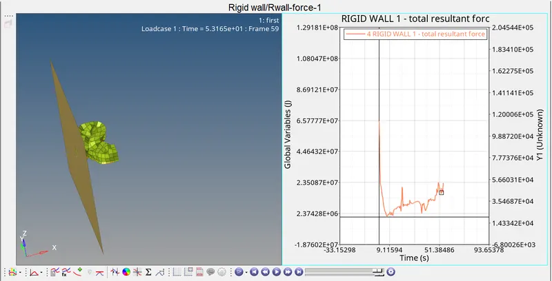
1) Base simulation with default values.
- The below image shows the graph plotted for internal energy,contact energy,hourglass energy and total energy.
- The below image shows the graph for rigid wall forces.
CASE2:
PROCEDURE:
- First import the model using the solver deck option and choose 0000.rad file.
- Now change the engine run time to 55ms under the engine cards.
- Go to the anim_dt to change the Tfreq to 0.916.( 55/60 = 0.9166)
- Go to properties and change the shell element properties of Ishell,Ismstr,Ish3n,N,Ithick,Iplas as recomended.
- Now go to analysis and click on radioss and give the number of threads as 4 and run the simulation.
- Once the simulation is done open the h3d file in hyperview and use the split screen option to open another window with hypergrpaphs 2D.
- now chose the T01 file and select the global variables to input the required energy plots.
- For rigid wall forces chose the rigid wall option and select the total resultant force.
IMAGES OF GRAPHS WITH MODEL:
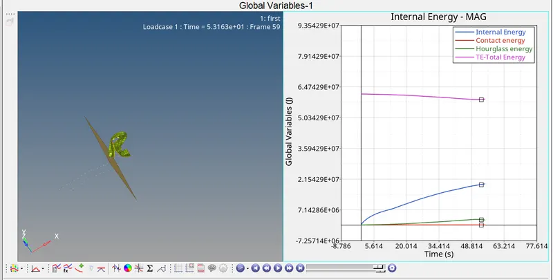
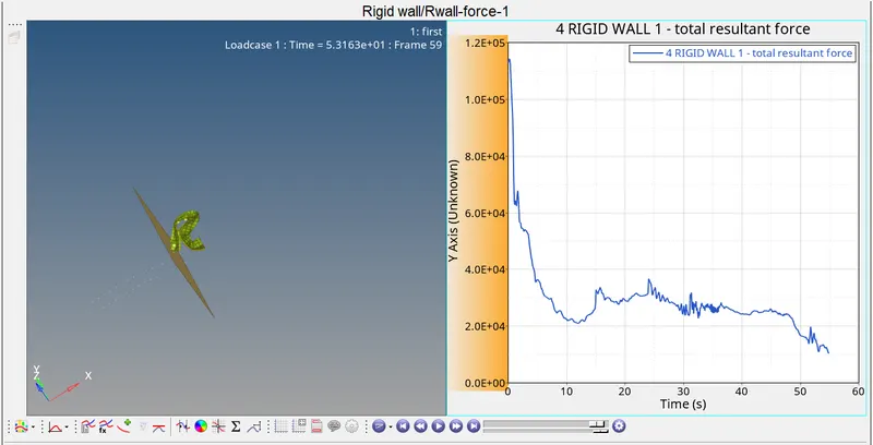
2) when run the simulation with given parameters(recomended properties of Ishell,Ismstr,Ish3n,N,Ithick,Iplas)
- The below graph shows the plots of internal energy,total energy,hourglass energy and contact energy.
- The below graph shows the plot of rigid wall forces.
Comparison
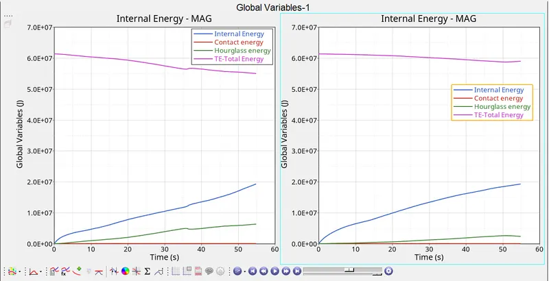
1) Comparison of internal,contact,hourglass and total energy.
- Left side plot represents the plot with default properties, while the right one is with recomended values.
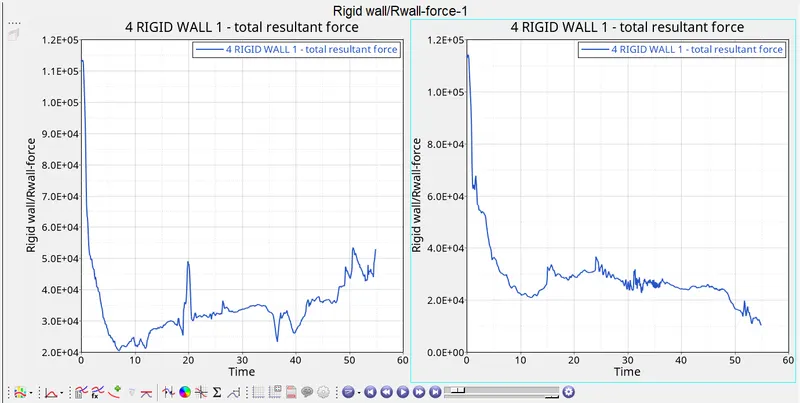
2) Comparison of rigid wall forces.
- Left side plot represents the plot with default properties, while the right one is with recomended values.
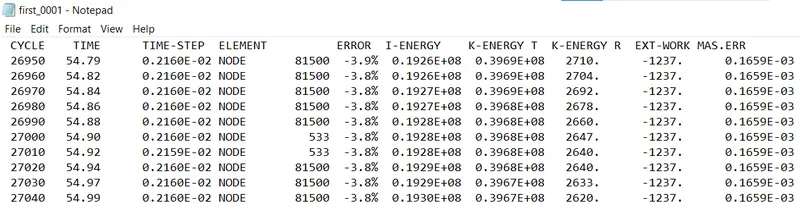
3) The below image shows the error percentage of few cycles for the first simulation:

4)The below image shows the error percentage of few cycles for the second simulation:
Results:
- From the above shown graph we can observe that there is slight variation in the results between both the simultation.
- This is because of the parameters that we have used in the second simulation.
- The following parameters have been used in the second simulation:
1) Ishell=24
2) Ismstr=2
3) Ish3n=2
4) N=5
5)Ithick=1
6)Iplas=1
- The hourglass energy value has come down by some considerable amount in the second simulation,which implies that we have obtained better results.
- The internal energy plot tends to dip in the second simulation,where as it tends to raise in the first simulation.
- The contact energy remains the same in both the cases.
- The total energy is slightly higher in the second case compared to the first case.
- The total resultant force of rigid wall tends to increase in the first case, while it tends to decrease towards zero in the second case.
- The above entered parameters is the reason why we have a difference in results of both the simulation.
- The above mentioned parameters are used in order to obtain accurate and precise results to our simulation.
Conclusion:
Yes,there is change in the results of the plots between the first and second simulation.
This is because of the change in parameters that we have used in both the simulation.( parameters are mentioned above).
HOURGLASS ENERGY:
Hourglass energy refers to the enerygy that produce zero strain and stress. The cause of this is because of reduced integration elements,because of which there will be numerical computational error which will make the elements too flexible. This can be overcome by improving the meshing quality ( refine the mesh and make it more smooth), and increase the number of integration elements.