Assignment 3-2D Element Formulation Challenge
2D Element Formulation
Objective: To simulate having a default property card and changing the property card and then compare the two cases.
Theory:-
Hourglass Effect:
In the hourglass deformation, the strain energy of element deformation is not computed it is also known as zero energy deformation mode. This can be seen in the post-processing where the elements have a zig-zag formation.
Normal Elements:-
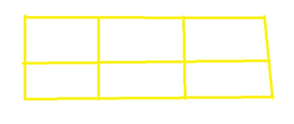
Hourglass Deformation:-
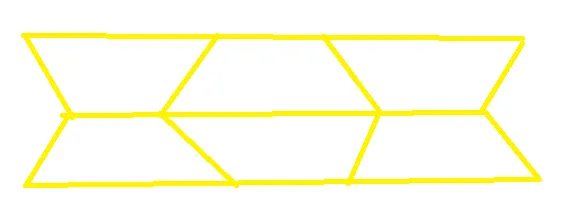
Cause of Hourglass effect:-
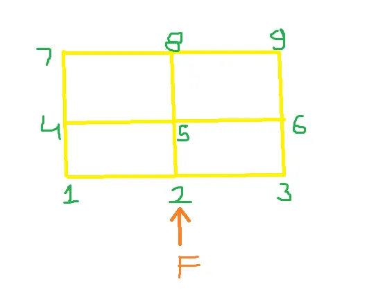
When a force F is applied to a node N2, the solver first calculates the acceleration of the node based upon the force applied then using acceleration solver calculates velocity and the displacement.
From the displacement, it calculates strain, and from the strain the stress. Which will be applied as a force on the next node N5. This is the process of calculation in the nodes. But in the case of element solver calculates through integration points using Gaussian Quadrature method.
There are two methods of integration:-
- Reduced integration scheme
- Full integration scheme
Reduced Integrated elements:-
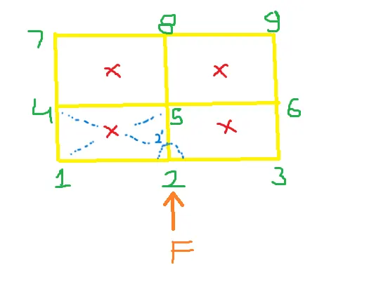
In the reduced integration when a force F is applied to a node N2 the displacement and the strain are calculated by the solver at the nodal level. In the element, the solver calculates results from the displaced node N2 and the other nodes 5,4, and 1. Using Gaussian Quadrature. This method is used in reduced integrated elements.
Therefore in this case element deformation energy is remain uncalculated which leads to the hourglass effect.
Fully Integrated Element:-
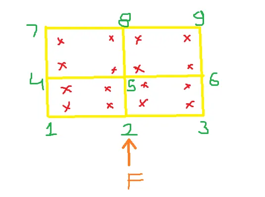
In this case, the results from nodes 1,2,4, and 5 were calculated at 4 integration points respectively.
Because of four integration points, results are very accurate but computational cost is very high. Reduced integration is computationally inexpensive but it is inaccurate because of the hourglass effect.
Methods to control Hourglass:-
1) Perturbation method (Ishell = 1,2,3,4)
- First hourglass deformation is detected with the relative motion of the nodes.
- When the hourglass is detected a force is applied to the node to stabilize the deformation
- This force is defined according to the element stiffness
- This force induces an artificial energy
- It is recommended for high-velocity problems.
2) Perturbation method Ishell = 24 (QEPH) = Stiffness method
- Hourglass yield depends on the natural yield
- Hourglass loading stiffness depends on the natural tangent modulus
- The hourglass treatment is done at the material level
- It is recommended for fewer velocity problems
- Less amount of hourglass energy is needed because it is going to be controlled before it arises.
Shell Element Formulation:-
RADIOSS provides both reduced and fully integrated 4 noded and 3 noded shell elements.
|
Nodes |
Elements |
Ishell |
Description |
Integration |
Rel. cost |
|
4 |
Q4 QBAT QEPH |
1,2,3,4 12 24 |
Belytshko&Tsay Batoz Improved under integration |
Reduced Full Reduced |
1.0 2.0 1.15 |
|
3 |
CO |
2 |
Standard Triangle |
Key Parameters:-
- Ishell: Select element formulation for 4-noded shells
- Ish3n: Select element formulation for 3-noded shells
- N: Choose the number of integration points through the thickness
- Ismstr: Specify small or large strain formulation
- Iplas: Choose the method for calculating post-yield strains
- Ithick: Determine if the thickness is constant under load, or if the element thins.
Procedure:-
Case1:
1) Open the Hyperworks and set the user profile as RADIOSS
2) Go to Import>Solver deck
3) Select the given file and press import
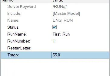
4) Assign the value of the time step in ENG_RUN as 55 ms as per the question. ( To capture 55 animation steps)
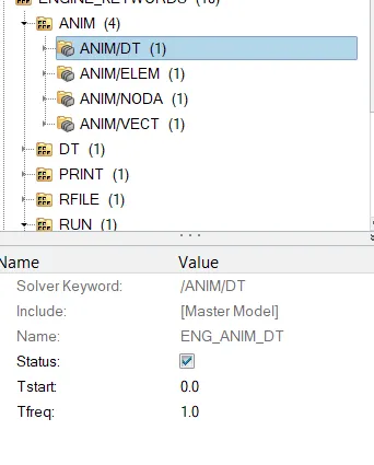
5) Set the Animation steps as per the question.
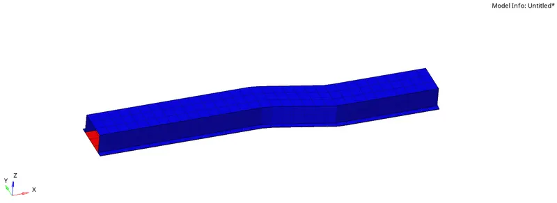
6) Simulate without changing the properties
These are default properties:
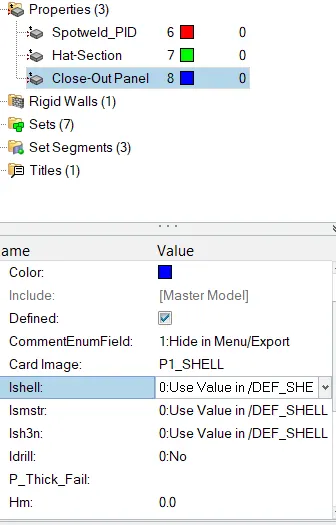
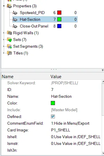
7) To run the simulation go to Analysis> RADIOSS

8) Select the folder to save files and then in the option write -nt 4

9) Click on Radioss it will show the job is completed
10) Open the Hyperview and load the .h3d file to see the animations.

11) See the Von Mises stress and the displacement contours
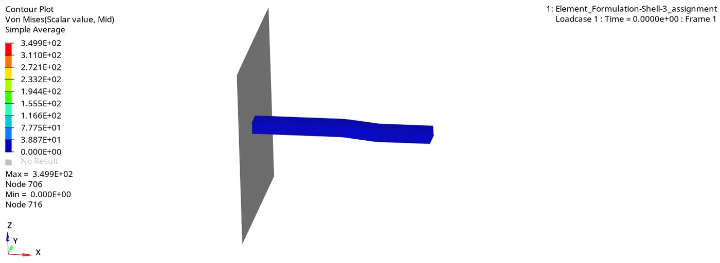
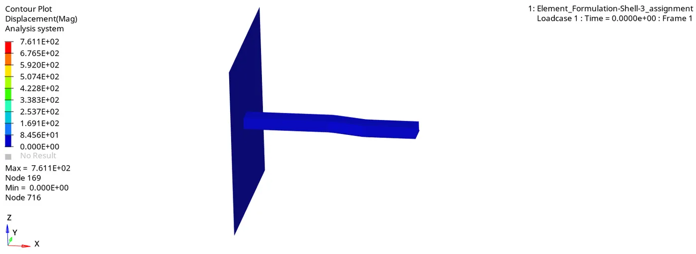
12) Go to the folder where the results are saved and then open the 0001.out file to view the simulation results.
13) Observe the energy error whether it is in the acceptable range or not.
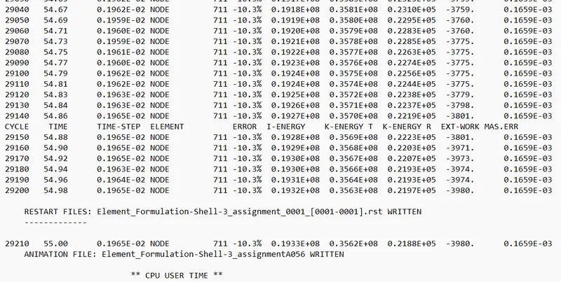
In this case, the energy error is reaching up to -10.3% and it is in the acceptable range.
Mass error is constant throughout the simulation at 0.1659E-03, it is also in the acceptable range.
14) Since the errors are in the acceptable range plot the rigid wall forces, internal energy, hourglass energy, contact energy, and total energy of the simulations in the Hypergraph 2D.
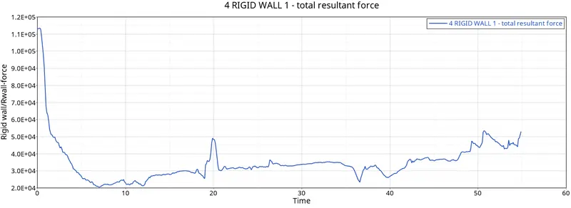
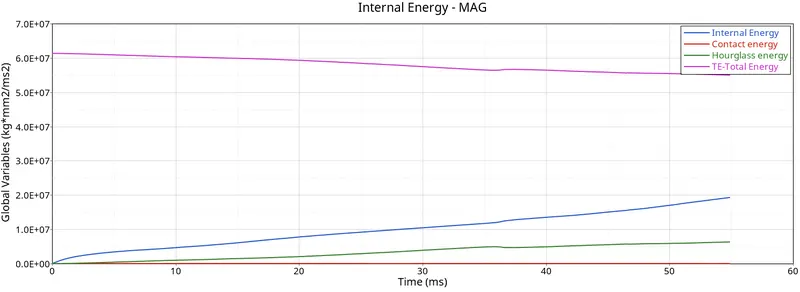
Observations:
- The rigid wall force is showing nonlinear behavior due to the variation of the force exerted by the crush tube on the wall throughout the simulation.
-
The Internal energy is increasing throughout the simulation which is due to the force developed on the tube due to deformation.
-
There is a slight increase in hourglass energy throughout the simulation.
-
Contact energy remains zero throughout the simulation
-
The total energy of the system has a slight decrease from the start to the end of the simulation.
Case2:
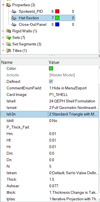
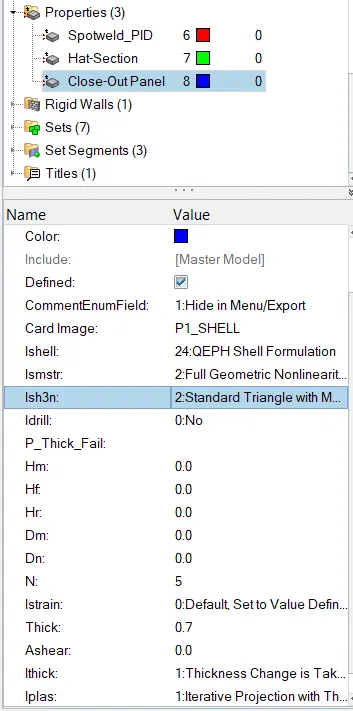
Assign the recommended parameters in the property.
Recommended properties:
| Parameters | Comment | |
|
Ishell =24 |
QEPH 4 nodes shells are the best combination of cost and accuracy. | |
|
Ismstr=2 |
Full geometric nonlinearities (default)with possible small strain formulation activation in RADIOSS Engine. | |
|
Ish3n=2 |
Standard 3 noded shell (C0)with modification for large rotation(default) |
|
| N=5 | A number of integration points are set to 5 for accuracy bending. | |
|
Ithick=1 |
Thickness change is taken into account for accuracy. |
|
|
Iplas=1 |
Iterative plasticity for good accuracy. |
1) Assign the properties in the model.
2) Run the simulation as above.
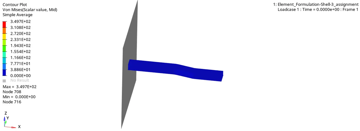
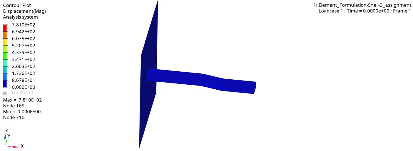
3) Plot the Von Mises and the displacement contours
4) open the 0001.out file to view the simulation results.
5) Observe the energy error whether it is in the acceptable range or not.
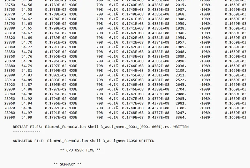
In this case, the energy error is reaching up to -0.1% and it is in the acceptable range.
Mass error is constant throughout the simulation at 0.1659E-03, it is also in the acceptable range.
6) Since the errors are in the acceptable range plot the rigid wall forces, internal energy, hourglass energy, contact energy, and total energy of the simulations in the Hypergraph 2D.
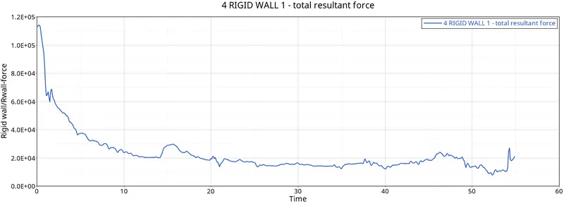
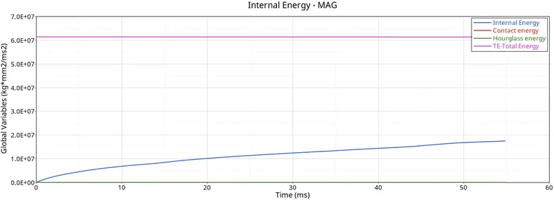
Observations:
- The rigid wall force is showing nonlinear behavior due to the variation of the force exerted by the crush tube on the wall throughout the simulation.
-
The Internal energy is increasing throughout the simulation which is due to the force developed on the tube due to deformation.
-
Contact energy and hourglass energy remain zero throughout the simulation.
-
The total energy is constant throughout the simulation.
Comparison:-
|
Basis for comparison |
Case1 |
Case2 |
Comment |
|
Hourglass Energy |
Increasing |
Zero |
Elements have physical stabilization in case2 because of QEPH elements |
|
Energy error |
-10.3% |
-0.1% |
Because no hourglass energy is required to balance the energy |
|
Total Energy |
Decreasing |
Constant |
Low energy error in case2 |
|
Contact energy |
Zero |
Zero |
Same for both the cases |
|
Internal Energy |
Gradually increasing |
Gradually increasing |
|
|
Rigid wall forces |
Non-linear |
Non-linear |
Lower in case2 |
|
Maximum Displacement |
7.611E+02 |
7.810E+02 |
Slightly higher in the case2 |
Conclusion:-
- Learned about the hourglass effect
- Learned how to perform simulation in RADIOSS
- Learned how to plot the curves in the Hypergraph2D
- Learned how to generate animations in the Hyperview.