Assignment 3-2D Element Formulation Challenge
Aim :
To Infer and compare the base Simulation results of given component with and without element modifications.
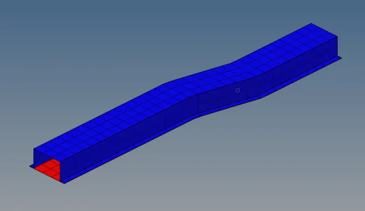
Given Component :
Procedure :
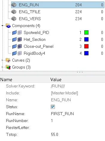
1.Setting Run time
Change the Run time of simulation in ENG_RUN under cards as shown below
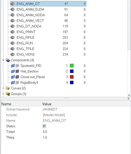
2.Changing Animation steps
We change the total animation steps to 50, so we change the Tstart and Tfrreq as 5 and 1 respectively under ENG_ANIM_DT.
3.Run a base simulation :
Now we change the simulation time, Tstart and Tfreq
But we didnt change the element properities.
Now ANALYSIS < RADIOSS
Select the destination place and select the INCLUDE CONNECTOR checkbox and click the RADIOSS.

Now solver runs the simulation and through out the results in text form.
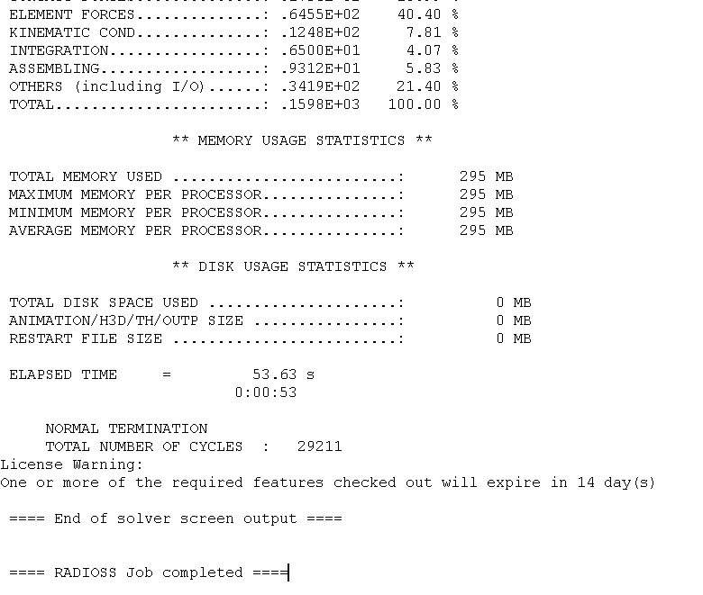
4.Energy Error Insecption :
Now we have to check the Energy error in our simulation.
For that we have open the 0001.out file in Notepad.
Now check the error percentage and error must be in negative and decreasing.
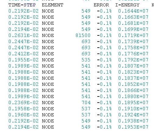
5. Ploting Other Graphs for Default element Formulation :
Now click the RESULT button in the HYPERWORKS SOLVER VIEW.
It opens the HYPERVIEW . Then split the screen into two and open HyperGraph 2D
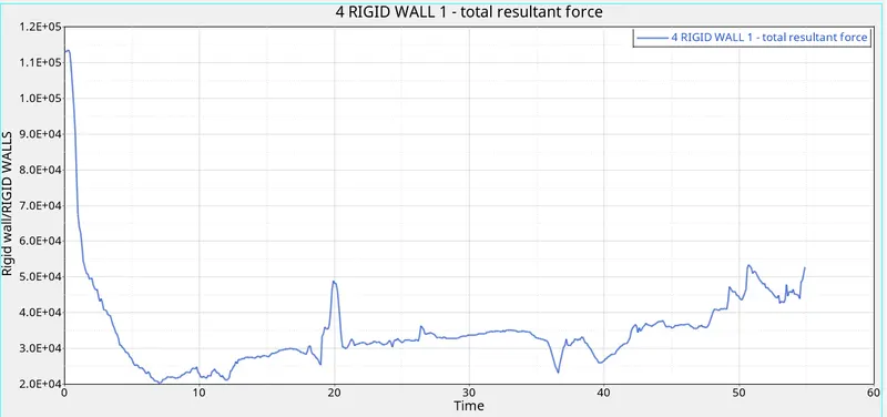
First we plot the RIGID WALL FORCE.
In this below graph we infer that the force is high at inial and fall suddendly rise sharply at 20ms and gradually rise at the end.
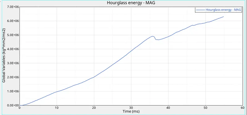
Secondly we can plot the HOURGLASS ENERGY
From the below graph we infer that the Hourglass energy is increasing because it 4 noded elements are taken as Q4 as default
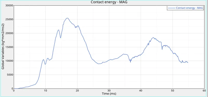
Thirdly, We can plot the CONTACT ENERGY.
Inn the below graph we can infer that contact energy is enerated minimal due to heat, vibration, etc
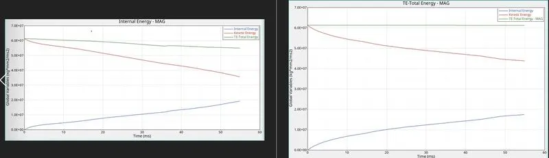
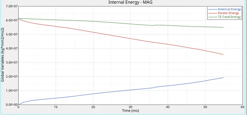
Finally, we can plot the INTERNAL ENERGY, KINETIC ENERGY & TOTAL ENERGY
In this below graph we can infer that the
Kinetic energy is decrases with respect to time (ie : It converted into strain)
Internal energy is increasing (ie : Deformation increases)
Total energy is slightly decreases due to loss of energy by contact, hourgalss energy, etc..
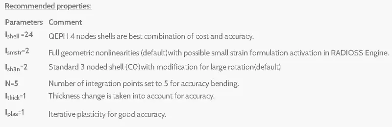
Changing Element Properties to Recommended :
we have to change the element properties as shown in the below image
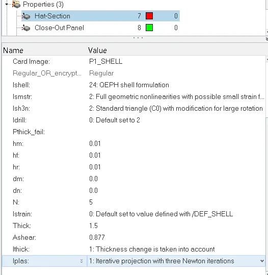
To change the elemment property, click the Hat section in the property card
Under that change the Ishell, Ismstr, N, Ithick, Iplas to recommended value.
3.Run a base simulation :
Now we change the simulation time, Tstart and Tfreq
But we didnt change the element properities.
Now ANALYSIS < RADIOSS
Select the destination place and select the INCLUDE CONNECTOR checkbox and click the RADIOSS.
Now solver runs the simulation and through out the results in text form.
4.Energy Error Insecption :
Now we have to check the Energy error in our simulation.
For that we have open the 0001.out file in Notepad.
Now check the error percentage and error must be in negative and decreasing.
5. Ploting Other Graphs for Default element Formulation :
Now click the RESULT button in the HYPERWORKS SOLVER VIEW.
It opens the HYPERVIEW . Then split the screen into two and open HyperGraph 2D
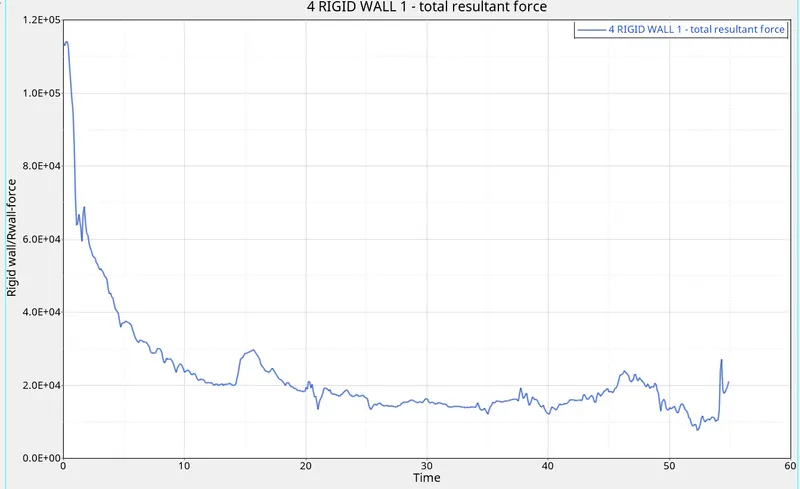
First we plot the RIGID WALL FORCE.
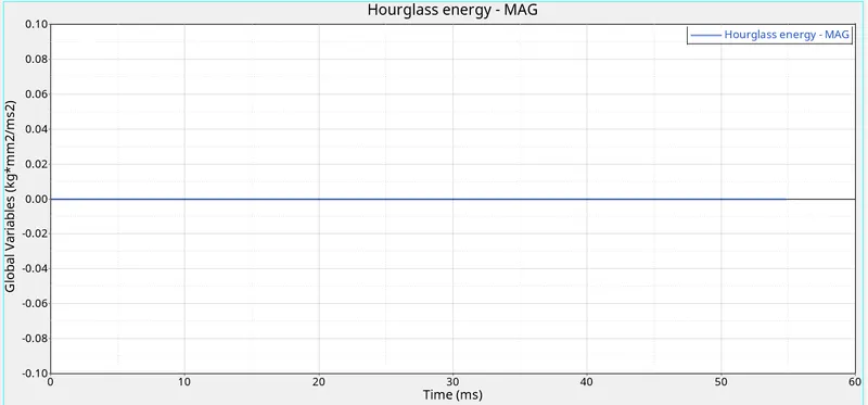
Secondly we can plot the HOURGLASS ENERGY
From the below graph we infer that the Hourglass energy is almost FLAT because it 4 noded elements are taken as QEPH ( HOURGLASS - PHYSICAL STABILIZATION )
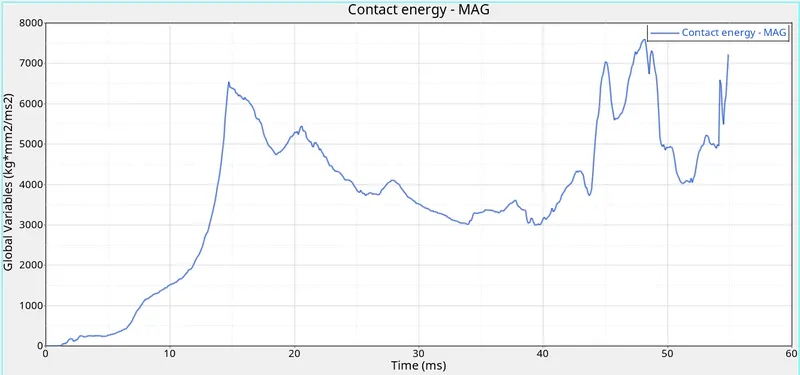
Thirdly, We can plot the CONTACT ENERGY.
Inn the below graph we can infer that contact energy is enerated minimal due to heat, vibration, etc
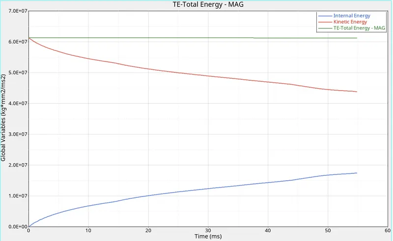
Finally, we can plot the INTERNAL ENERGY, KINETIC ENERGY & TOTAL ENERGY
In this below graph we can infer that the
Kinetic energy is decrases with respect to time (ie : It converted into strain)
Internal energy is increasing (ie : Deformation increases)
Total energy is slightly decreases due to loss of energy by contact, hourgalss energy, etc..
COMPARION :
1.HOURGLASS ENERGY *LEFT GRAPH ( WITHOUT ELEMENT PROPERTY MODIFICATION) & RIGHT GRAPH - (WITH ELEMENT MODIFICATION )*
We see that hourglass energy decrase drastically because of QEPH ELEMENT formulation.
This element formulation has improved under integrated and physical stabilization to reduce the hourglass energy
In 2nd case, hourglass energy is almost equal to zero
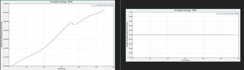
In 2nd case, we use the Ismstr is equal to 2 & Iplas is equal to 1 , thus it capture the large deformation with high accuracy.
And due to Iplas is equal to 1, solver accurately calculate the strain deformations even though after the yeild point is reached.
That is what the graph differs in the RIGID WALL FORCE and in CONTACT ENERGY GRAPH
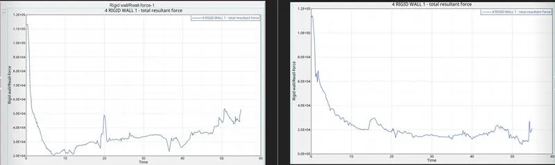
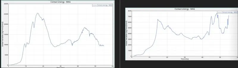
We clearly see that the TOTAL ENERGY graph is almost flaten in the case 2.
Because in case 2, we obtain the very least amount of HOURGLASS energy. so Total energy curve stays almost flat and contact energy is also neglegible value.