Assignment 2-RADIOSS Engine File Editing & 3D Meshing Challenge
- Check the material properties of the rail component and calculate the speed of sound in steel rail= ______________
Given-
M
Modulus of Elasticity, E = 210 GPa = 2.10 x 10⁵ N/mm2 = = 2.10 x 10³ g-mm/ms-mm2
Density, ρ = 7800 x 10-9 kg/mm3 = 0.007800 g/mm3
Speed of Sound, C= ?
We Know that,
∆T = l/C = `l/√(E/ρ)`
`C=√(E/ρ)`
C =`√((210000)/(0.0078))`
C = 5188.7 mm/ms
C = 5188.7 m/s
The speed of sound in steel rail is 5188.7 mm/ms
2. The length of the rail is about 1000 mm. calculate the time takes for a shock wave to travel from one end of the rail to the other
Given-
Modulus of Elasticity, E = 210 GPa = 2.10 x 10⁵ N/mm2 = 2.10 x 10³ g-mm/ms-mm2
Density, ρ = 7800 x 10-9 kg/mm3 = 0.007800 g/mm3
l = Length of Span = 1000 mm
Critical Time Step, ∆T = ?
We Know that,
∆T = l/C
∆T =1000/ 5188.7
∆T = 0.1927 ms
∆T = 0.1927 x 10⁻³ seconds
The time taken for a shock wave to travel from one end of the rail to the other is 0.1927 ms.
3. Time for sound to travel length of rail=______
For the length as per que. 2, i.e., 1000 mm, Time for sound to travel length of rail is 6.16 x 10⁻³ seconds and Speed of Sound is C= 1.62 x 105 mm/sec.
∆T = l/C
0.1927 = 1000/ C
C = 5188.7 mm/ms
C = 5188.7 m/s
4. Edit the engine file so that the stress wave can be monitored, moving from one end of the rail to the other during impact -this will require a termination time equal to the time it takes for the sound to travel the length of the rail(set on/RUN card)
Ans.- Go through the attached image fig. 1.
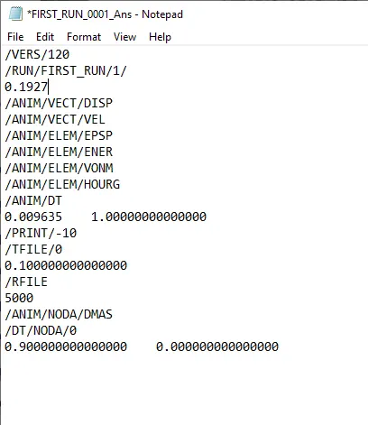
Fig.-1
5. Set the frequency of animation output to a time that will give 20 animation steps(/ANIM/DT)
Ans.- Refer Fig. 2.
Given-
No. of Animation Steps = 20
Critical Time Step, ∆T = 0.5 microseconds
∆T = 5 x 10⁻⁷ seconds
Speed of Sound, C= ?
We Know that,
TF =`∆T/(No.of Animation Steps)`
TF = `(5 x 10⁻⁷)/20`
TF = 2.5 x 10⁻⁸
TF = 0.000000025
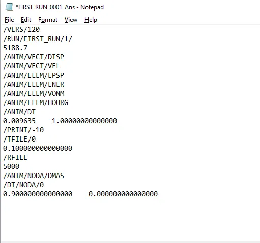
Fig.-2
6. Change /print -10
Ans.- Refer Fig. 2.
7. 3D Meshing Tetra & Hex Meshing of Component
Objective-
Meshing of given CAD Models using 3D Tetramesh & Hex Mesh and achieve stated Quality criteria using Hypermesh.
- Housing Model using 2D to 3D Conversion-
CAD Model Image-
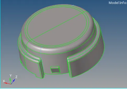
Fig.-3
Procedure-
- Import the provided CAD Model and analyze it properly. If there exist any problem in model through Quick Edit & surface edit panel, rectify the problem and prepare the model for 2D Meshing so that minimum element size length can be achieved.
- Now go to 2D Automesh panel and mesh all the surfaces of the model with element size 5 & elements trias only as shown in fig.4.
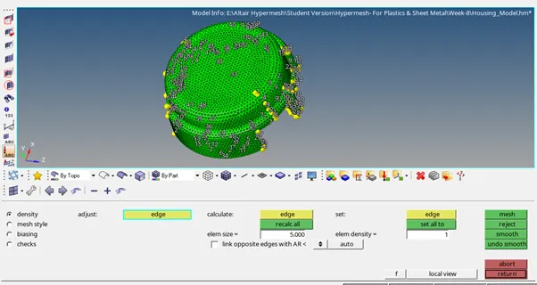
Fig.-4
- After meshing kindly check whether the specified quality criteria is achieved or not. But prior to checking mesh criteria input the quality parameters as shown in fig.5.
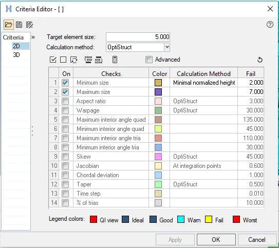
Fig.-5
- Now check the whether the provided quality index is achieved or not through quality index panel as shown in fig. 6. If not achieved through clean up tools, clear the failed elements.
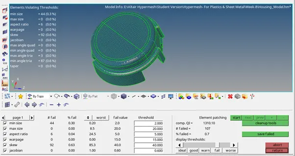
Fig.-6
- Now, through 3D tetramesh panel, go to Tetra Mesh tab and convert all the displayed 2D tria elements into tetra elements as shown in fig. 7.
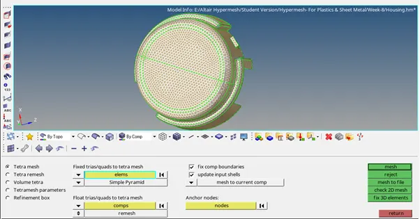
Fig.-7
- Once the meshing is done, through mask panel check whether the tetra elements have been created or not as shown in fig. 8.
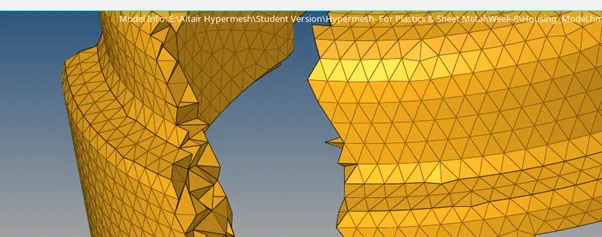
Fig.-8
- Since the tetra elements have been created, go for 3D elements quality check. Here we mainly deal with Tetcollapse. Check which are the elements violating tetcollapse value.
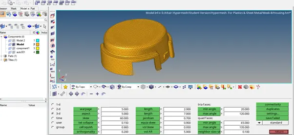
Fig.-9
- If any of the elements are failing due to tetcollapse, clear them either by remeshing them through tetra remesh panel as shown in fig. 10.

Fig.-10
- If suppose after remeshing also, some of the elements are violating tetcollapse, they can be cleared through manual options such as translating the nodes or changing the distance between them as shown in fig. 11 & fig. 12.
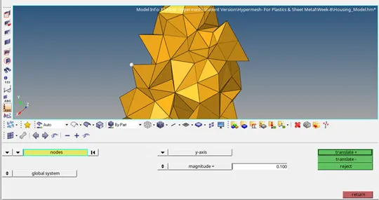
Fig.-11
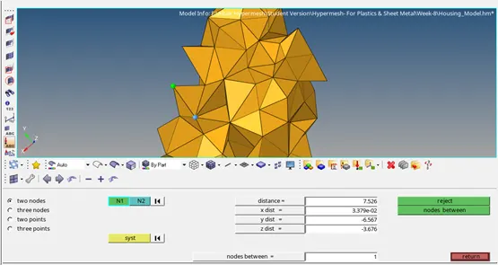
Fig.-12
- Now, check the quality of the mesh.
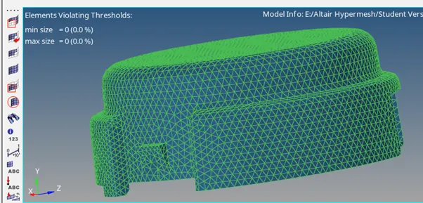
Fig.-13
- Now delete all the 2D elements present in the model, through delete panel by following the stated steps as shown in fig. 14.

Fig.-14
- Now the meshed model is as shown in fig. 15.
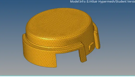
Fig.-15
Result-
As per the given criteria, models have been meshed.
2. Hex Meshing of Arm Bracket-
CAD Model Image-
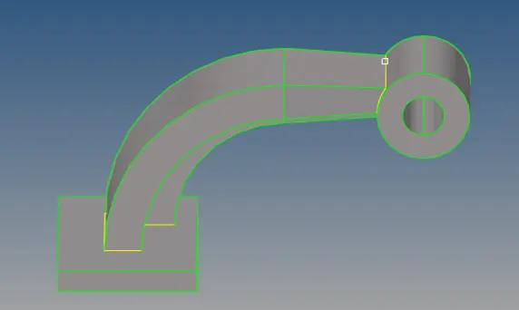
Fig.-16
Procedure-
- Since here we are using different methods to create the Hex mesh so organize the different surfaces in different collectors through organize panel as shown in fig. 17.
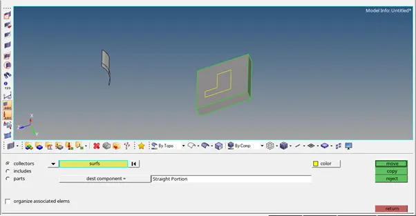
Fig.-17
- At the bottom bracket the hex mesh have been created using element offset method. So, first 2D Mesh the surface and create the Hex mesh as shown in fig. 18, 19, 20 & 21.
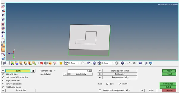
Fig.-18
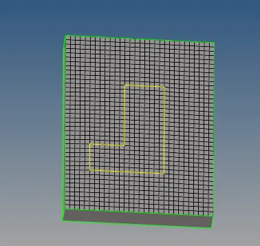
Fig.-19
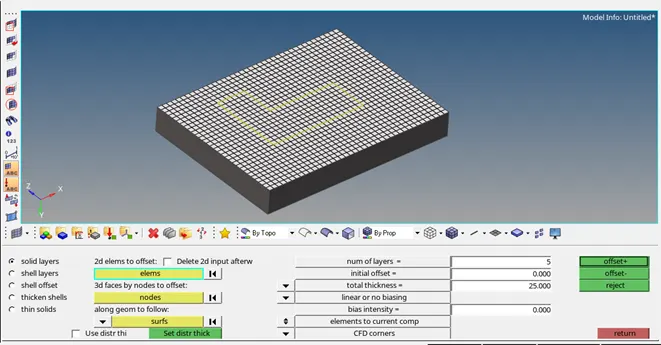
Fig.-20
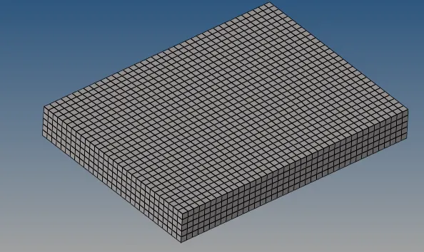
Fig.-21
- For the curved bracket use Spin option to create the Hex mesh.
- Create the center node of the arc as shown in fig. 22.
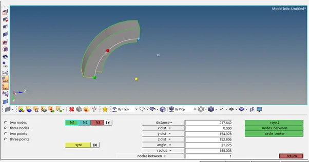
Fig.-22
- Now create the 2D Quad elements and spin them to Hex mesh as shown in fig. 23,24 &25.
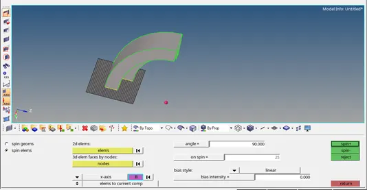
Fig.-23
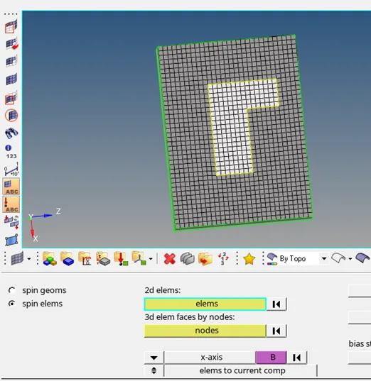
Fig.-24
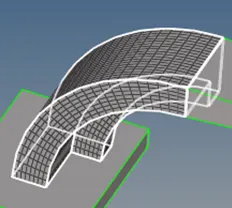
Fig.-25
- For the straight portion the Hex mesh will be created using Linear Solid. So first extract the faces to create the 2D Elements as shown in fig. 26.
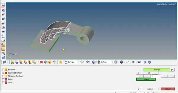
Fig.-26
- Now create the equal no of elements on the other face also as shown in fig. 27.
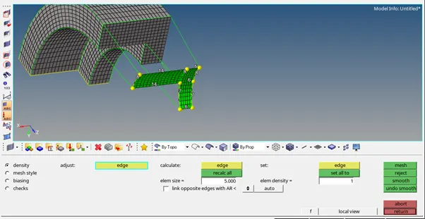
Fig.-27
- Now create the Hex mesh using Linear solid as shown in fig. 28 & 29.
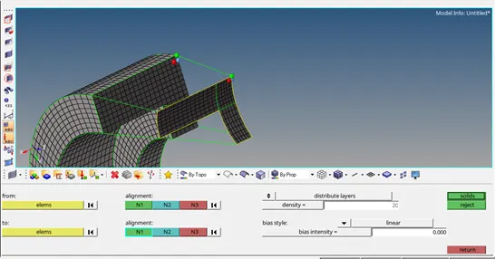
Fig.-28
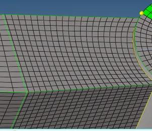
Fig.-29
- For the Boss the Hex mesh will be created using Solid Map. So first create the 2D mesh as shown in fig. 30.
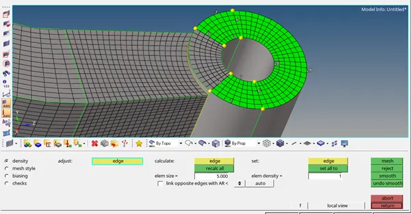
Fig.-30
- Using solid map create the Hex mesh as shown in fig. 31 & 32.
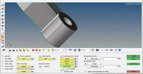
Fig.-31
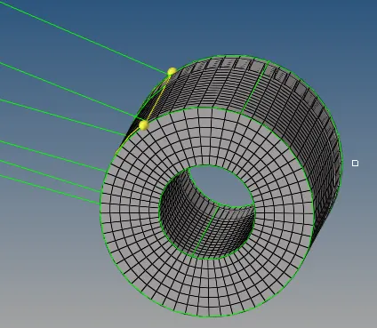
Fig.-32
- Once the meshing is completed delete the 2D Elements as shown in fig. 33.
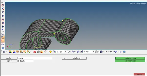
Fig.-33
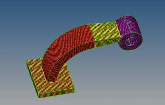
Fig.-34
Result-
As per the given criteria, models have been meshed.