Assignment 2-RADIOSS Engine File Editing & 3D Meshing Challenge
OBJECTIVE:
- To check the material properties of the rail component and calculate the speed of sound in steel rail, Time for sound to travel length of rail.
- To edit the engine file so thet stress wave can be monitered, Set the frequency of animation output to a time that will give 20 animation steps.
- To perform 3d meshing on given components with given quality parameters.
Questions:
1. Check the material properties of the rail component and calculate the speed of sound in steel rail=5188.75 mm/μs.
From the given data in starter file:
E = 210000 MPA
Rho = 0.0078 g/mm^3
Speed of sound in rail (c) = √(E/Rho)
= √(210000/0.0078)
= √2692307.692
= 5188.75 mm/μs OR m/s.
2. The length of the rail is about 1000 mm.calculate the time takes for a shock wave to travel from one end of the rail to the other.
3.Time for sound to travel length of rail = 0.192724644 μs.
L = 1000 mm
Time = length / speed of sound
= 1000 / 5188.75
= 0.192724644 μs.
4.Edit the engine file so that the stress wave can be monitored, moving from one end of the rail to the other during impact -this will require a termination time equal to the time it takes for the sound to travel the length of the rail(set on/RUN card)
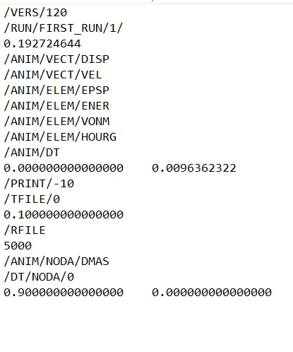
5.Set the frequency of animation output to a time that will give 20 animation steps(/ANIM/DT)
Time frequency for 20 steps = (0.192724644/20)
= 0.0096362322
6.Change /print -10.
The print value is "-10".
3D meshing:
Given components:
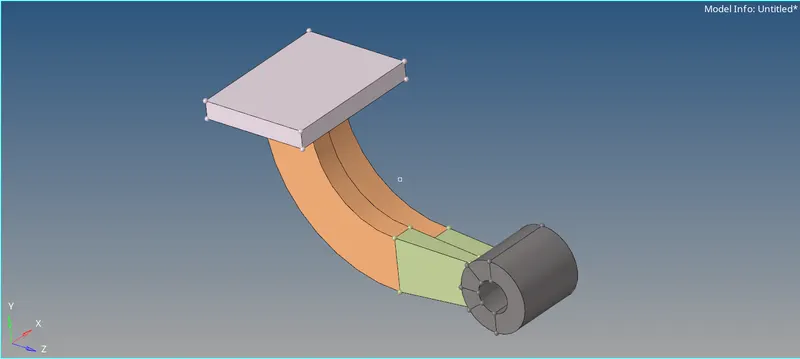
- Arm Bracket
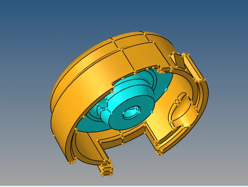
- Housing
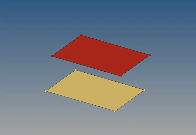
- 1D Element
Connections:
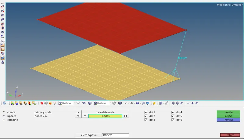
Using rigid body:
Go to 1D deck >>> rigids >>> Select Slave nodes >>> master node is auto calculated >>> Create
For master node, auto-calculation has to be selected. The master node is created at the center of mass to the slave nodes.
If needed we can provide Degree Of Freedom to the nodes.
We can use update to modify the selection.
In this case Slave nodes are independent and master node is dependent.
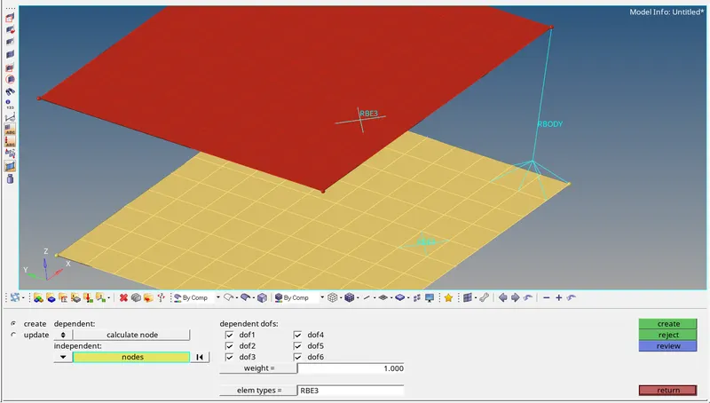
RBE3 connection:
This connection is different from rigid connection. In rigid connection, if force F is acting on master node, Same force is transmitted to the slave nodes in respective direction.
In Rbe3 the forces are transmitted according to the weights i.e., based on distance of slave from master node.
In RBE3 the Master node is auto-calculated and is independent, the slave nodes are dependent.
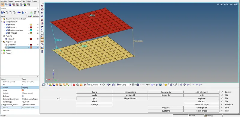
Truss or rods:
Truss is an Element which can take only axial loads either tensile or compressive.
1D >>> Rods >>> Select the nodes >>> create.
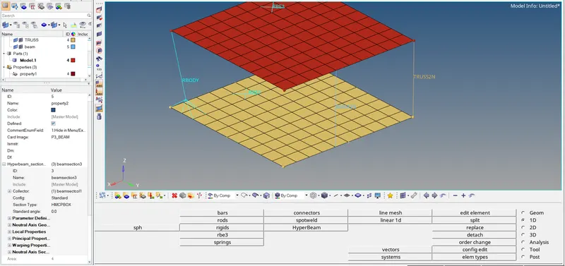
Bars:
1D >>> Bars >>> select the nodes >>> provide the orientation
This beam element can take axial and bending loads.
- Housing
There are two sub assemblies in the model: Inner part, Outer part.
3D meshing of inner part:
Using 2D >>> Auto mesh >>> Slecting all surfaces >>> Target length as 5mm >>> Element type as trias >>> Mesh
2D mesh is generated, we convert this 2D mesh into 3D mesh by Tetra Mesh in 3D deck.
3D deck >>> select the 2D elements generated
3D deck >>> Tetra mesh parameters >>> Provide minimum length to capture features properly >>> Tet collapse size
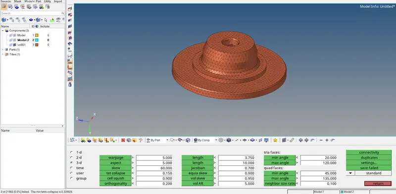
The below image shows the 3D volume with tet collapse errrors as 0.
3D meshing of outer part:
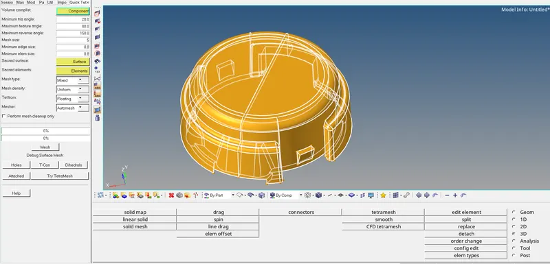
As there are lot of de-featuring to be done, We go with Quick tetra which auto-defeatures and provide volume mesh.
Utility browser >>> Selct the component >>> Provide min. tria angle >>> Provide minimum size >>> Mesh.
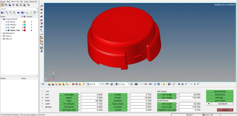
The below figure shows the 3D mesh generated with many off-elements.
To clear those off-elements,
Go to 3D deck >>> Tetra mesh >>> Tetra remesh >>> select the elements >>> Provide tetra parameters >>> Proceed with tetra mesh >>> Remesh.
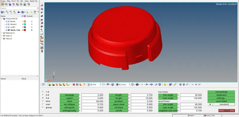
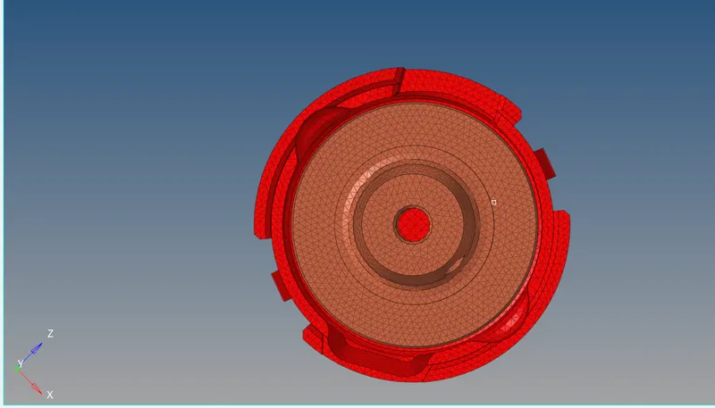
The below image shows the 3d volume mesh of the housing component.
- Arm Bracket
There are 4 sub-assemblies and one extra face.
1. Square component
2. Curved component
3. Taper Component
4. Boss
3D meshing a square component:
First, A 2D mesh is genertaed on the face using only quad elements with target element size of 10mm.
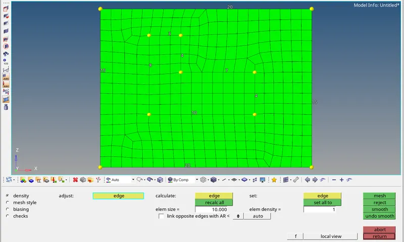
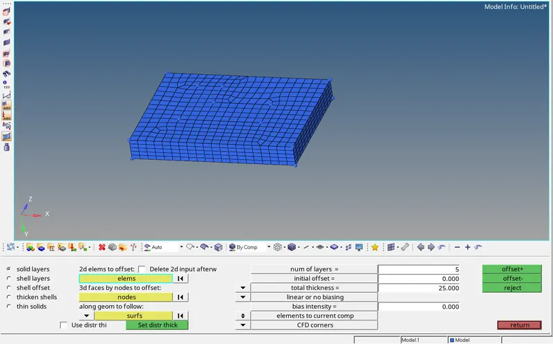
3D deck >>> Offset elements >>> select the elements to offset >>> provide total thickness >>> provide numer of layers >>> Offset.
A 3D volume mesh is generated as shown below.
3D Mesh of curved component:
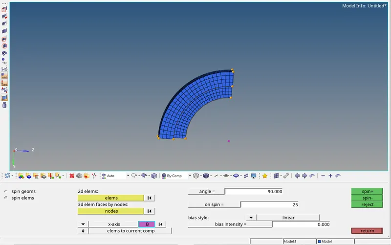
The extra face which is meshed is spinned onto the component
3D deck >>> Spin >>> Select 2D elements to spin >>> Provide the angle (90* in this case) >>> Provide on spin numer of layers as 25 >>> Proceed with spin.
3D volume mesh of Curved component is generated as shown below.
3D mesh of taper component:
convert the 3D elements on curved feature into 2D So we can use linear mapping to get volume mesh.
Tools deck >>> Faces >>> Select the component / face >>> Find Faces.
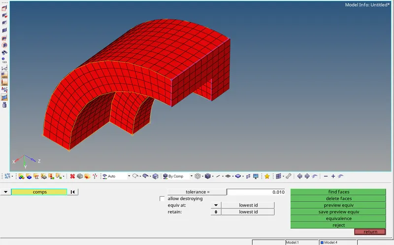
Mesh the other end of the taper bar and same number of elements are to be maintained w.r.t the other end.
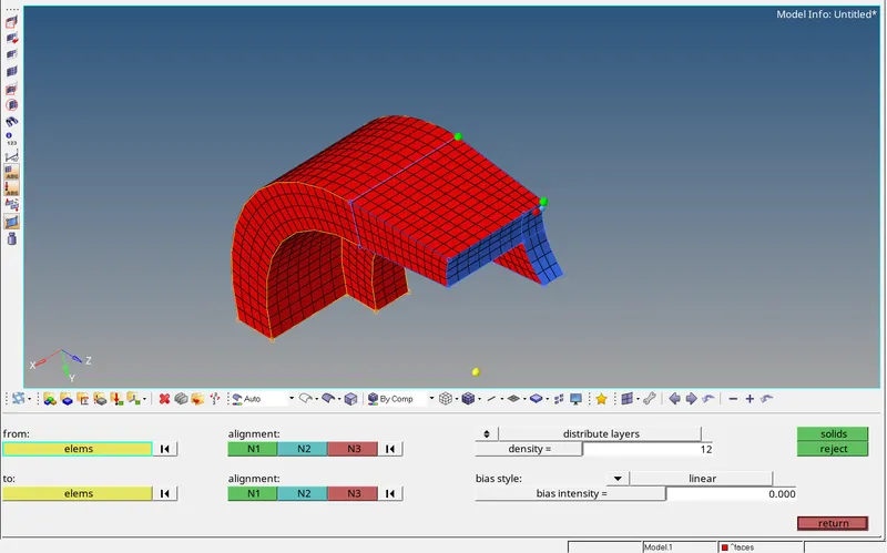
Use Linear solid >>> Select From elements >>> Select To elements >>> Provide the Alignment same on either of the faces >>> Solids.
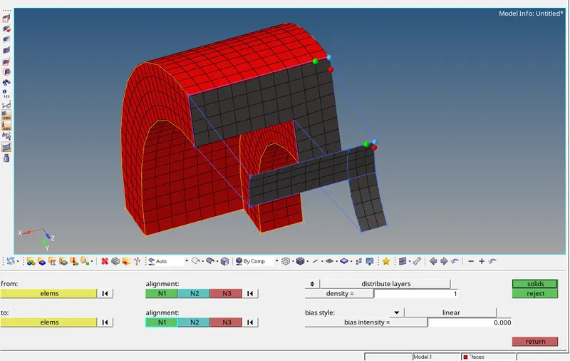
The 3D Volume mesh is generated as shown below.
3D mesh of Boss:
Mesh one end of Boss using 2D mesh and number of nodes at one end and the other end has to be same.
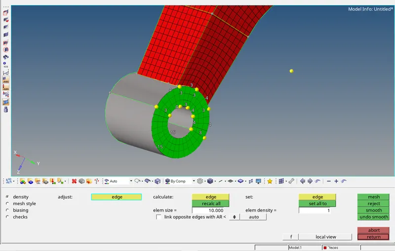
3D deck >>> Solid map >>> general >>> Select destination geometry >>> Select along geometry to mixed >>> select the line and nodes in the orientation of mesh to be generated >>> mesh.
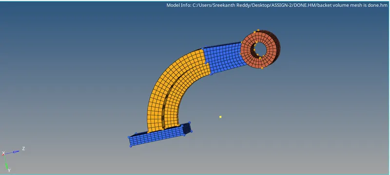
the below image shows the volume mesh i.e., generated.
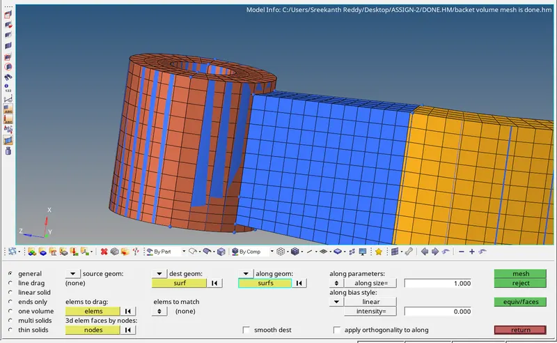
The below image shows the volume mesh i.e., generated.
Conclusion:
- By using the various techniques, 3D meshing is done on arm bracket and housing components to the given Quality criteria.
- The connections are performed on the given 1D model.
- The speed of sound in steel and time taken by the sound wave to travel through the length of rail and time frequency of animation output has calculated and respective modifications are done in the engine file.