Assignment 2-RADIOSS Engine File Editing & 3D Meshing Challenge
Objective 1:
To check the material properties of the rail component and calculate the speed of sound in steel rail.
Solution:
Young's modulus, E = 210000 N/mm^2
Density, `rho` = 0.0078 K kg/l
Speed of sound, C = `sqrt`E/`rho`
C = `sqrt`210000/0.0078
= `sqrt`26923076.92
= 5188.745 m/s
`therefore` The speed of sound in steel rail = 5188.745 m/s
Objective 2:
To calculate the time taken for a shock wave to travel from one end of the rail to the other.
Solution:
Length of the rail, l = 1000 mm
Speed of sound in the given steel material, C = 5188.745 m/s
Time taken for sound to travel the length of rail = l/C = 1000/5188.745 = 0.192 ms
Objective 3:
- To edit the engine file so that the stress wave can be monitored, moving from one end of the rail to the other during impact.
- To set the frequency of animation output to a time that will give 20 animation steps.
Procedure:
- Go to Import solver deck and select Radioss as the file type. Choose the file to be imported and click on import.
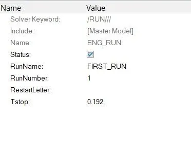
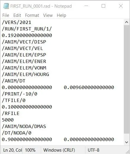
- To change the run time, click on the ENG_RUN card in the cards collector. Change the Tstop value to 0.192.
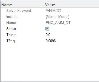
- To set the frequency of animation output, click on the ENG_ANIM_DT card in the cards collector. Change the Tfreq value to 0.0096.
Result:
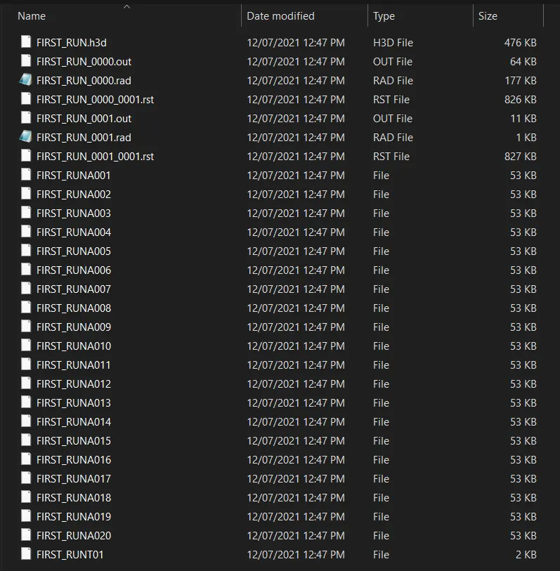
Thus the ENG_RUN card is edited to monitor the stress wave during the impact and ENG_ANIM_DT card is edited in order to achieve 20 animation time steps.
Objective 4:
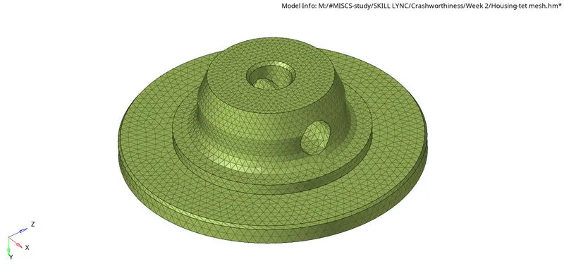
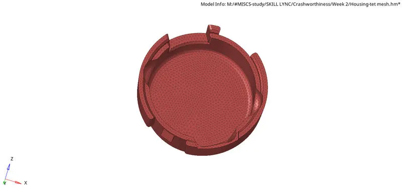
To create tetramesh for the given models by satisfying the required quality criteria.
Procedure: 2D to 3D conversion
- To import the cad model, goto New model > Import geometry and select the file to import.
- Initially, by using the toggle edge option, all the unneccesary construction lines can be suppressed.
- Other Manual cleanup methods are quick edit > toggle edge, quick edit > split surf, quick edit > washer split, quick edit > unsplit surf, quick edit > project point & quick edit > replace point.
- Remove all the unnecessary points by using the quick edit > add/remove point.
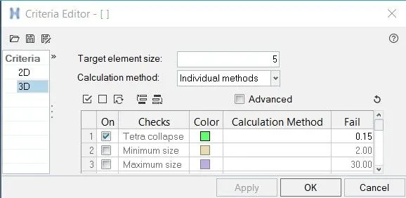
- Then goto preferences > Criteria file settings and update the quality criteria.
- In order to mesh the surfaces, goto 2D > Automesh and enter the mesh element size = 5.
- Choose the surface to be meshed and click on the mesh button.
- To check the element quality, goto Tools > Check elements or press F10 or goto 2D > elem cleanup.
- The failed elements can be corrected by using the elem cleanup or the elem quality index > cleanup tools or using any of the manual operations.
- To check if there are any duplicate elements present, press F10 > duplicates. If duplicates are present, then click on Save failed and goto Delete > elements > retrieve and delete the excess elements.
- Goto Tools > edges, select the surfaces and click on find edges to check if any of the elements are disconnected from the neighbouring elements. To rectify this, click on equivalance or goto > 2D replace and join the nodes manually.
- To create Tetra mesh, goto 3D > Tetramesh > choose all the 2d elements and click on mesh.
- To check the element quality, goto Tools > Check elements > 3D or press F10 > 3D.
- To rectify all the failed elements, perform 3D > Tetra mesh > Tetra remesh or use the node translate option to manually clear all the quality issues.
Result:
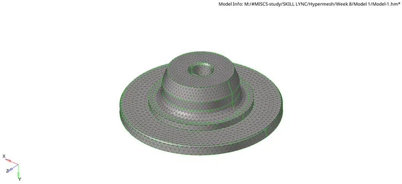
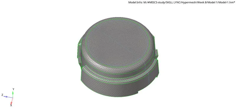
The components in the given model are meshed with tetra elements by satisfying the required quality criteria.
Objective 5:
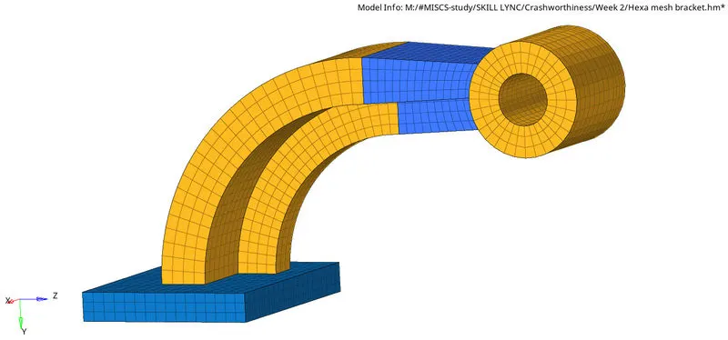
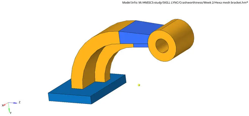
To create hexmesh for the given model by satisfying the required quality criteria.
Procedure:
To import the cad model, goto New model > Import geometry and select the file to import.
Base:
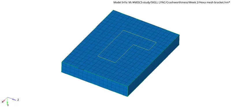
- The upper surface of the base is meshed with quad elements with the size of 10mm.
- To mesh the base component with HEX mesh, goto 3D > Solid map, select the elements to be dragged, destination geometry and along geometries. Enter the along size for the number of elements to be created between the source and destination.
Model.3:
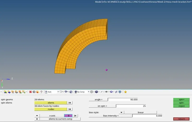
Goto 3D > spin > spin elems, select the 2D elements from model.2 collector and select the base point as the arc centre. Enter the angle value as 90 deg and the on spin value as 25.
Model.4:
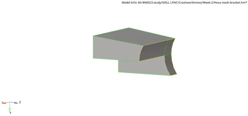
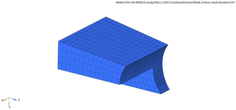
- Due to the varying dimensions at both the ends, linear solid approach has to be used. Linear solid approach needs from and to elements.
- 'From' elements can be derived from the model.3 elements by using Tool > Faces.
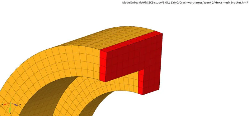
- 'To' elements can be created by meshing the end surface of the model.4 component.
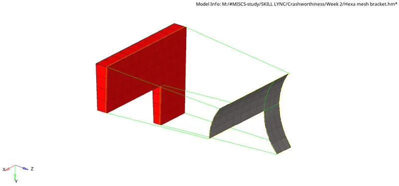
To create Hexa mesh, goto 3D > Linear solid, select the from and to elements, select the alignment nodes, enter the density value and click on solids.
Model.5:
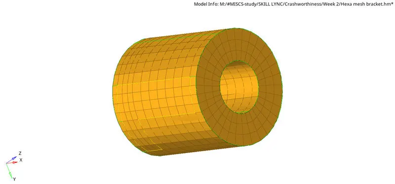
- The upper surface of the cylindrical component is meshed with quad elements with the size of 10mm.
- To mesh the component with HEX mesh, goto 3D > Solid map, select the elements to be dragged, destination geometry and along geometries. Enter the along size for the number of elements to be created between the source and destination.
Free edge check:
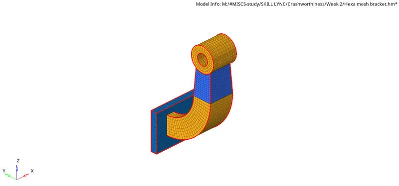
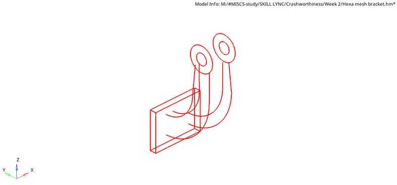
Goto Tools > edges, select the surfaces and click on find edges to check if any of the elements are disconnected from the neighbouring elements. To rectify this, click on equivalance or goto > 2D replace and join the nodes manually.
Result:
The component in the given model is meshed with hexa elements of size = 10mm.