Assignment 2-RADIOSS Engine File Editing & 3D Meshing Challenge
Aim: Understanding the basics in HyperWorks solver Radios
Objective:
- Check the material properties of the rail component and calculate the speed of sound in steel rail
- The length of the rail is about 1000 mm. Calculate the time it takes for a shock wave to travel from one end of the rail to
the other. - Time for sound to travel the length of the rail
- Edit the engine file so that the stress wave can be monitored, moving from one end of the rail to the other during an impact
- Set the frequency of animation output to a time that will give 20 animation steps(/ANIM/DT)
- Change /print -10.
- 3d meshing tetra mesh and hex mesh
Target tet size=5mm,hex size=10mm,tet collapse=0.15.
Procedure :
Step 1: Extracting the material properties
The given file is the exclusive .rad file for the Radioss solver in Hypermesh.
In order to extract the material properties for the given rail component, we need the starter file for it.
There are 2 inputs to the Radioss solver
1. Starter input deck :
The starter input deck contains all the information of the model which includes all the nodes, elements, material properties,
initial condition as a time for simulation, velocities, loads, and many more.
The starter input file is written in text format so it can be opened and edited and run in the solver. Engine input deck. The
name of the starter file starts with runtime_0000 and it remains the same for all.
2. Engine input deck
The engine input file contains all the results obtained after the simulation. The engine file name starts with the
runtime_001.rad the 001 is the time for the simulation is run. If the same data is run again the file name will be 002.rad and
so on.
Here the material properties are extracted by opening the file in notepad.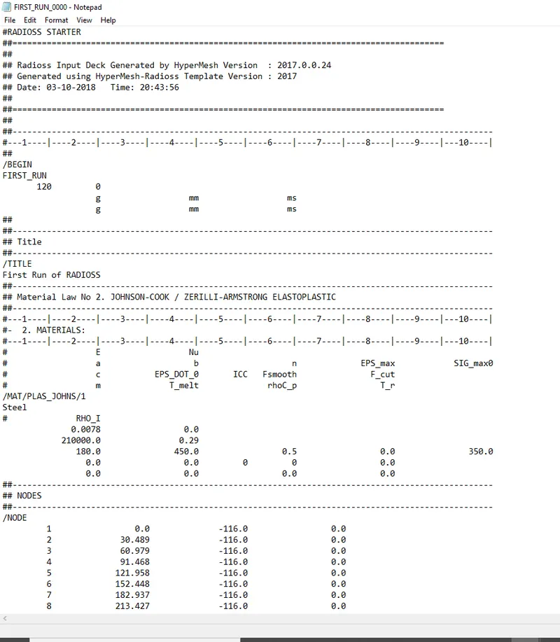
Fig 1- Starter file
- The information that we need mainly here is Young’s modulus and the density for the component. All the other properties can
also be obtained in the same file.
Young's modulus - 210000
Density /rho- 0.0078
nu/possion ratio- 0.29
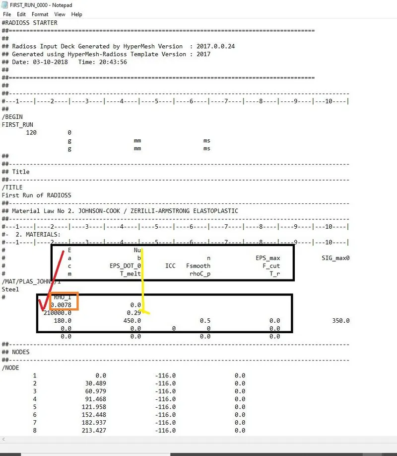
Fig- Material properties in starter file
To calculate the speed of the sound through the material can be calculated using the formula
Y/E- youngs modulus
p- density od the material
v- the speed of sound
v=sqrt root(Y/p)
= sqrt root(210000/0.0078)
v = 5188.74- Step 2: Time is taken for the shock wave to travel
The shock wave here is nothing but the sound speed that is going to travel along the component length.
The formula and the steps to calculate the time is as followed.
Time or delta T= 0.1927 ms
- Step 3: Time along the length of the rail
Since the rail length is the same as above i.e 1000mm so the time taken for the sound to travel the length of rail is 0.1927.
- Step 4: Editing the termination time
The termination time is the time for which the simulation will be run.
The time for termination is required to set the time for the sound to travel the component.
To do that open the file in notepad and change the run time to 0.1927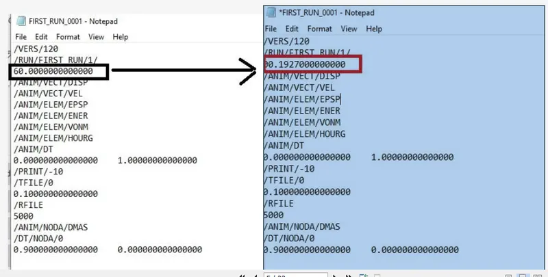
- Step 5: Frequency of animation
To set the frequency for 20 animation steps the termination has to be divided by the animation step.
frequency= termination time / animation step
= 0.1927/20
= 0.009635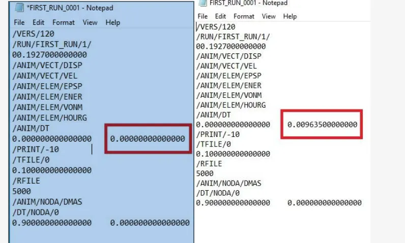
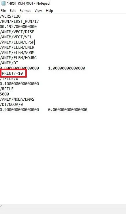
- Step 6- Change the print
The file is opened in notepad and print is changed to -10
- Step 7- 3d meshing
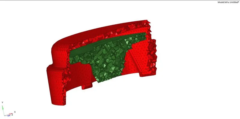
Tetra meshing : - Performing the 2d shell mesh :
Now the 2D meshing is performed using only tria elements and all the shell kept under the mentioned quality criteria.
go to 2D>automesh> element size >5 >type >tria >mesh - After the shell mesh is performed they need to be converted into solid tria elements. So select 3D> tetra mesh option
Then select the elements under the fixed tria/quad to tetra option and then do the mesh - Fixed tria to tetra option ensures the connectivity of the tria with the tetra.
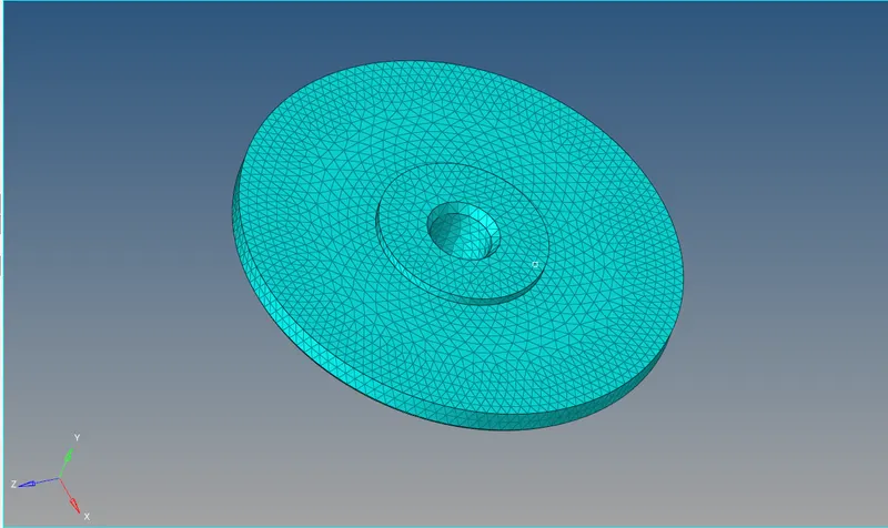
Fig- Tetra mesh
- Use the mask option to see if the volume mesh is performed correctly.
Using the volume tetra : - This method is one of the quickest methods to perform the tetra meshing.
- The steps to perform the volume tetra are as
followed. - The volume tetra requires only the solid model so no need to delete the solid here. Go to 3D> volume tetra
- The volume tetra has the same parameters that need to be fed
- Select the solid as available on the workspace
- Choose the element size as 5 as mentioned
- Switch on the use proximity and use curvature option
(These two options are used to refine the mesh in the region of curves or converging parts so that there is a smooth transition of
the elements.)
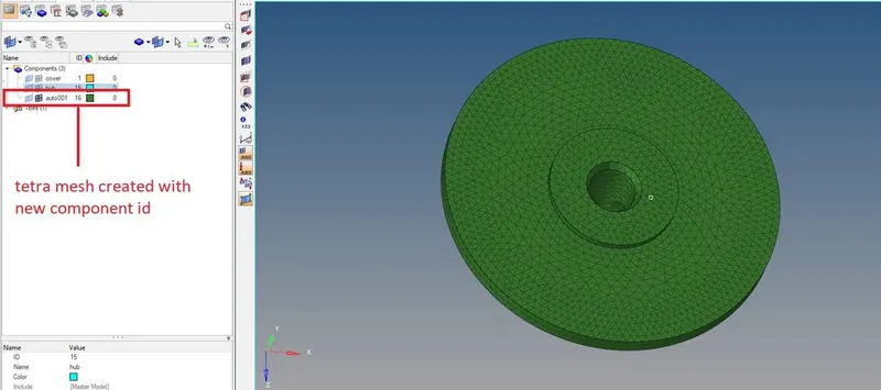
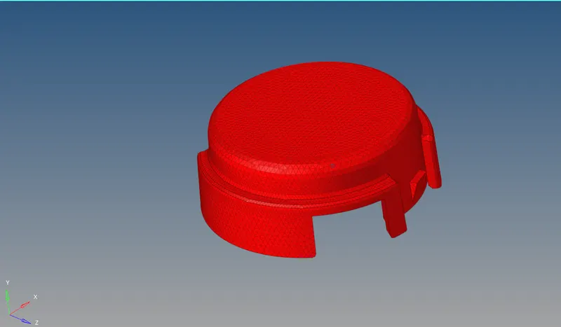
Fig- tetra mesh using Volume tetra
- Hexa meshing :Hexa meshing is meshing using the brick element.
- There are various options available in 3D meshing for the Hexa element that
can be used. Some of the tools to create Hexa meshing are explained below
Element offset : - Import the model into the HyperWorks and then create the 2D shell mesh using the quad element only on the base of the
component.
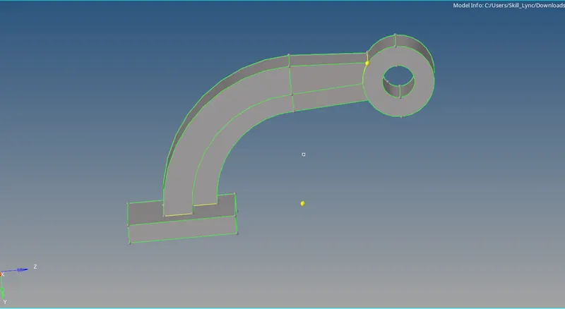
Fig- Model imported for hexa meshing
- 2D>automesh >element size >10 > type >quad
Only quads elements should be there.
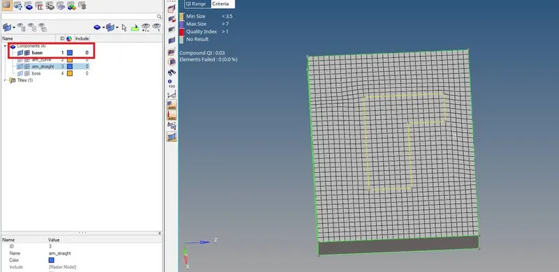
Fig- 2D shell using quad on Base part
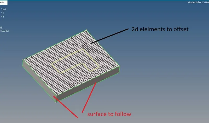
In order to convert the quad into Hexa, we use Element offset. Since the base, the part is a simple rectangular part its easy
to use the offset method because the offset surface is the same as the above surface
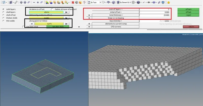
Go to 3D>element offset > solid layers
Select the 2D elements to offset as 2D quad elements created
Geometry to follow as surface that is
Select the number of layers 5 since the thickness is 25 >then offset
Fig- Hexa mesh using the element offset
2. Spin
To mesh the curved arm the SPIN tool can be used for Hexa along the arm.
In order to use the spin tool we need the centre point for the curve to spin the mesh in the proper direction
Go to distance or F4> 3 node > select the nodes > centre point
Switch on the base shell elements using the mask>elements >by config >quad4
- Go to 3D>spin >spin elements
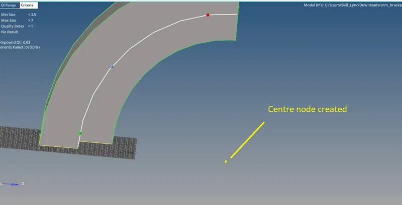
- Angle is 90
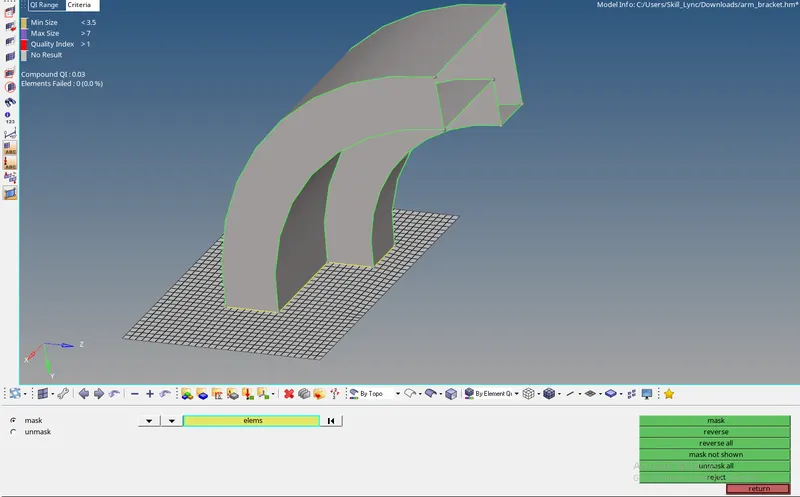
- On spin elements as 25
- Select the 2D elements as the L shaped region quad elements that are the base of the curved arm
- Spin along Xaxis and base point as centre node > offset
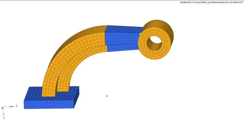
Fig- Hexa mesh using Spin
3. Linear solid
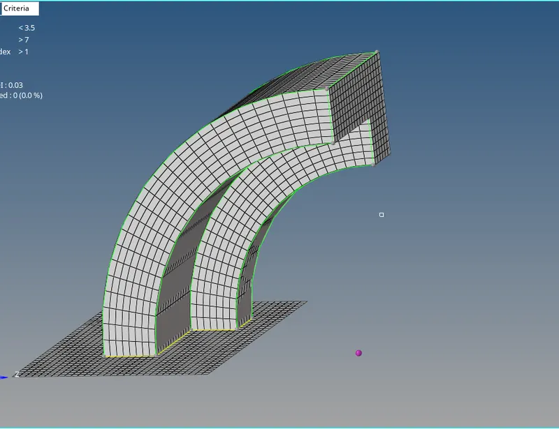
Create the faces from the arm curve. Since the arm created is a 3D mesh and we need face elements as the base for the
next arm part.
Tool>faces >comp>faces
Now create the 2D quad shell elements on the end face of the arm. Note the number of elements should match the
elements on the other face.
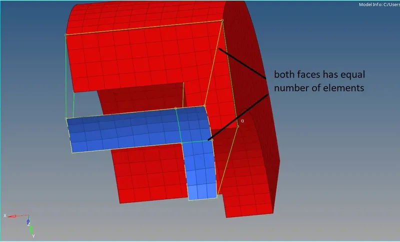
Go to 3D> linear solid
From elements and to elements can be selected as the two end faces elements respectively. The alignment node should be
the same on both the faces
Density can be set 12 >solids
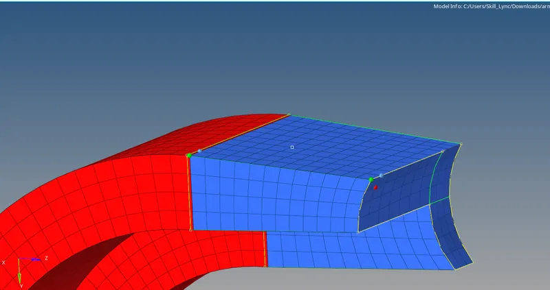
Fig- arm part Hexa mesh using linear solids
Same as using the solid map tool, the boss part of the component can mesh with the Hexa meshing.
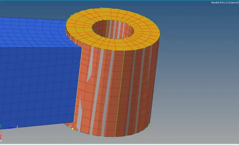
Fig- Hexa mesh for boss using solid mapping
1D elements :
The 1D elements ll line elements, whether straight or curved, are called 1D element in which they have translational and
rotational displacement functions.
Examples of the 1D element are the truss element and beam element.
To deploy the 1D elements the steps are as followed
Import the model into HyperWorks and perform the 2D meshing
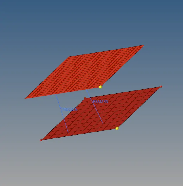
Fig - Model for 1D elements
Go to 1D> bars > select the node from each plate
select the orientation of the 1d beam element
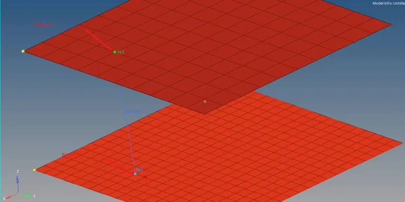
Fig- 1D element using bars (beam)
Results :
- The speed of sound for the given material is 5188.74
- The time for a wave to travel is 0.1927ms
- The frequency of 20 animation step is 0 009635
- The 3D tetra meshing for the housing component
- The Hexa meshing for Arm bracket
- 1D element meshing
Conclusion
The Radioss starter file and engine file editing and all the components for 3D meshing were also meshed successfully