Assignment 2-RADIOSS Engine File Editing & 3D Meshing Challenge
AIM: The main aim of this challenge are as follows:
1) To edit the given engine file according to the given question so that the stress wave can be monitored.
2) To create the tetra mesh for given housing model.
3) To create the hexa mesh for arm bracket model.
OBJECTIVE: The objectives of this challenge are as follows:
1. To calculate the speed of sound in steel rail.
2. To calculate the time taken by shock wave to travel from one end to another end of the rail.
3. To edit the engine file parameters such as run time and frequency time.
4. For the given housing model, 2D tria elements must be created with target element size of 5 mm and convert these 2D elements to 3D elements using tetra mesh subpanel option without any tet collapse (0.15) failure.
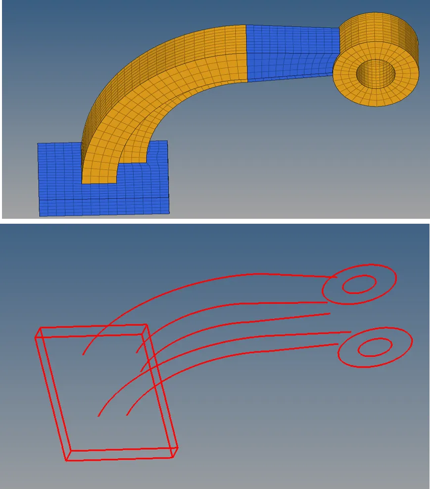
5. For the given arm bracket model, 2D quad elements must be created with target element size of 10 mm and convert these 2D quad elements to hexa elements.
PROCEDURE:
Editing the RADIOSS engine file:
1) Before starting the calculations, we should know the material properties and their units used in the given problem. _0000.rad file was used to know material properties and their units.
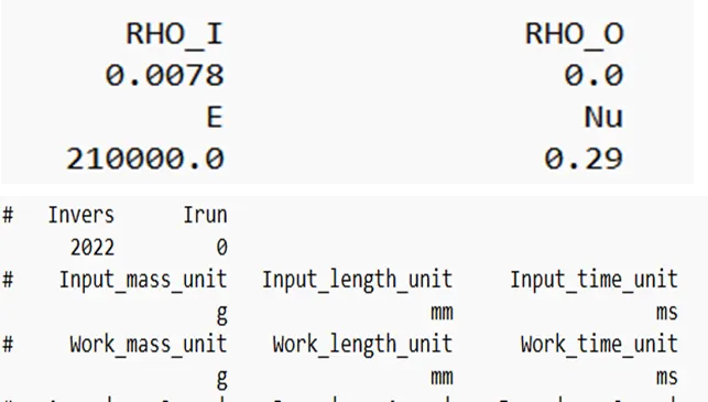
2) After knowing the material properties, we must make sure that all the properties units should be consistent before proceeding to the calculations.
3) Unit consistency and required calculations are shown in the below image.
E=210X103 Kg-m/S2/mm2=210X103X106 gm-mm/S2/mm2=210X109 gm-mm/S2/mm2
ρ= 0.0078 gm/mm3
Ø Speed of sound in steel rail=`sqrt(E/ρ)` =`sqrt((210X10^9)/0.0078` =5188745.21 mm/s=5188.74mm/ms=5188.74m/s.
Ø Length of the rail=1000mm
Time taken= length of the rail/speed of sound in steel rail=1000/5188.74 =0.1927 ms.
Ø Time for sound to travel length of the rail=0.1927ms.
4) From the above calculations, the following values were obtained:
Ø The speed of sound in steel rail = 5188.74 mm/ms or 5188.74 m/s.
Ø Time taken by shock wave to travel from one end to another end of the rail=0.1927ms
Ø Time for sound to travel length of the rail= Time taken by shock wave to travel from one end to another end of the rail=0.1927ms
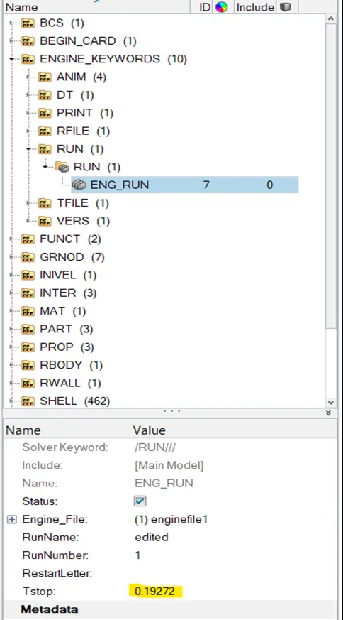
5) The run time (SOLVER BROWSERàENGINE_KEYWORDSàRUNàTstop =0.19272) for the simulation should be updated to 0.1927ms as per the above calculations. Run time can be edited by using hyperworks or can be directly edited from _0001.rad text file. If we are directly editing from the text file, we need to be more cautious about number format.
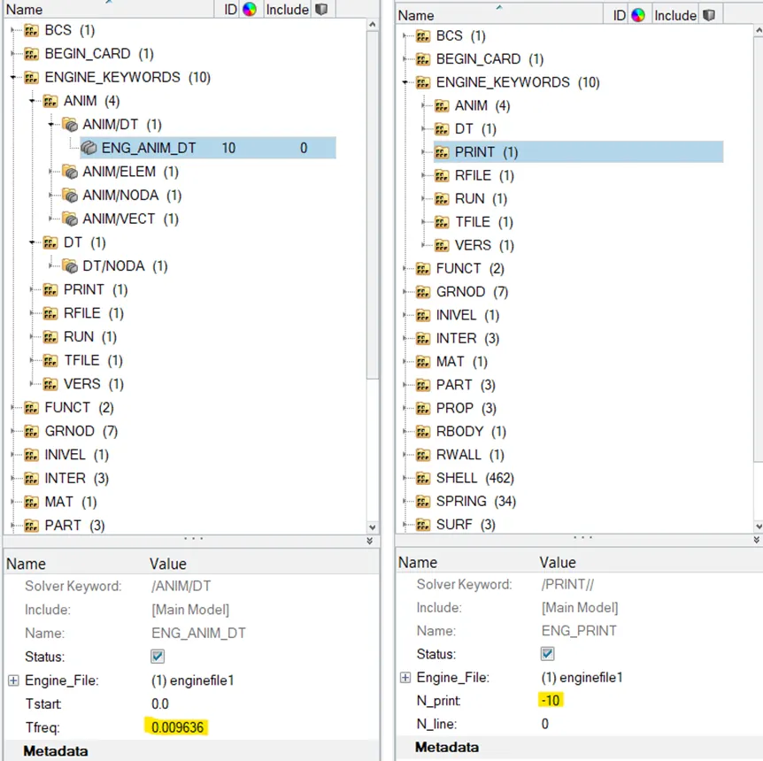
6) For 20 animation steps frequency time calculation is shown in the below image.
Tfrequency= Time for sound to travel length of the rail/20=0.1927/20=0.009636ms
7) Frequency time (SOLVER BROWSERàENGINE_KEYWORDSàANIM àANIM/DTàTfreq=0.009636) needs to be updated to 0.009636 as per above calculations. Change the print value (SOLVER BROWSER àENGINE_KEYWORDS àPRINT àN_PRINT=-10) to -10.
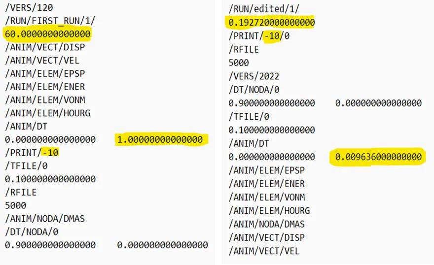
8) After updating the values, we can export the above model as solver deck file. We can get two text files after exporting they are _0000.rad &_0001.rad files. The above updated values in hyperworks gets automatically updated in the engine text file.
9) Engine file parameters before and after updating the values in the hyperworks are shown in the below image.
3-D tetra meshing of housing model:
1) In this challenge, there are totally 2 components and each of them should be meshed separately.
2) The CAD file was imported using import geometry option.
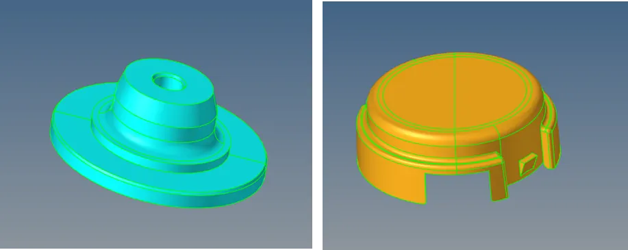
3) After importing the geometry, any free edges or non-manifold edges needs to be removed before performing meshing.
4) Defeaturing is done where ever it is required so that the 3D elements are free from tet collapse failure.
5) After defeaturing, tria mesh (2DàAUTOMESHàMESHTYPEàTRIASàELEM SIZE=5) was deployed on the components with element size of 5 units.
6) 2D elements were converted into tetra mesh by using tetra mesh subpanel(3DàTETRAMESH) option and final 3D mesh images are shown below. By masking (TOOLSàMASKàELEMENTS) some of the elements we can confirm the formation of tetramesh.
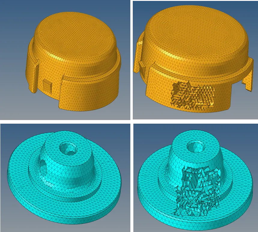
7) After deploying 3D mesh tet collapse must be checked using check elements subpanel option (TOOLSàCHECK ELEMENTSà3DàTET COLLAPSE=0.15). Tet collapse failure elements can be corrected either by tetra remesh (3DàTETRAREMESH) or translate (TOOLSàTRANSLATE) option.
8) 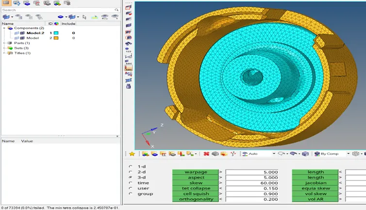
finally after creation of 3D elements, 2D elements were deleted.
3-D hexa meshing of arm bracket model:
1) In this challenge, 3D-hexa mesh must be deployed on the given arm bracket model.
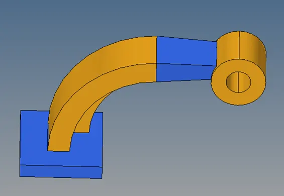
2) The given FE model file was imported by using import geometry option.
3)
Initially 2D quad elements with element size=10mm were deployed on the base component and these 2D elements were converted to 3D elements by using line drag option. (3DàLINE DRAGàDRAG ELEMENTS)
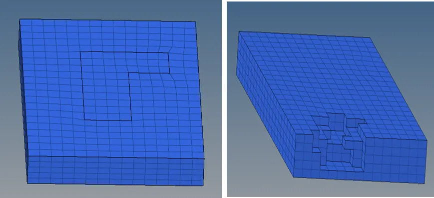
4) Hexa mesh on the arm curve component was generated by using spin option (3DàSPIN àSPIN ELEMENTS) and selecting the 2-D elements of l-shaped surface on the base component.
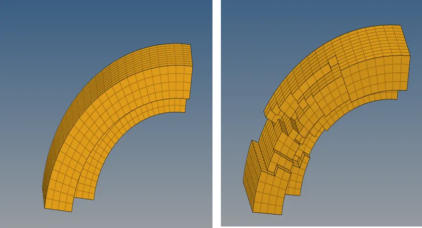
5) Before generating a mesh on arm straight component, we need to extract 2-D elements (TOOLSàFACES) from the arm curve component.
6) Linear solid (3DàLINEAR SOLID) option was used to deploy the hexa mesh on the arm curve component.
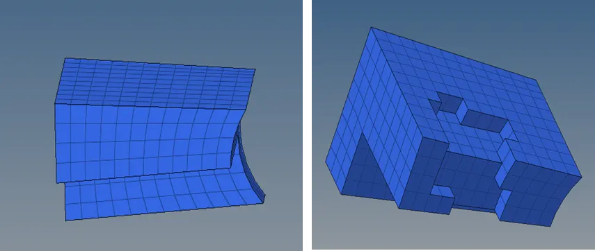
7) Finally for boss component solid map (3DàSOLID MAPàGENERAL) option was used to generate hexa mesh.
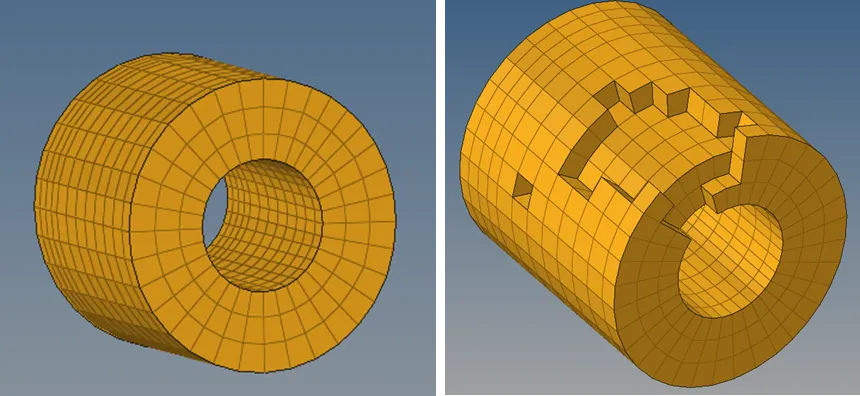
8) Check for connectivity (TOOLSàEDGES) after finishing meshing. Free edges should not be present at the middle of the component.
CONCLUSIONS:
Ø Learnt about the information contained by the different RADIOSS files.
Ø Learnt about how to edit the engine file.
Ø Learnt about how to deploy tetra and hexa mesh for the given models.
RESULTS:
1) Successfully deployed tetra mesh and hexa mesh on the given models.
2) All calculations were performed according to the given data and parameters were edited using hyperworks.