Assignment 2-RADIOSS Engine File Editing & 3D Meshing Challenge
Assignment 2-RADIOSS Engine File Editing & 3D Meshing Challenge
1. Aim
- Generate 3D Tetra Mesh on model 'housing. hm' and 3D Hexa Mesh on the model 'arm_bracket.hm' and ensure both meshes obey the mentioned quality criteria.
- Using the given RADIOSS Engine Files, find and perform
1. Check the material properties of the rail component and calculate the speed of sound in steel rail=_______
2. The length of the rail is about 1000 mm. Calculate the time it takes for a shock wave to travel from one end of the rail to the other.
3. Time for sound to travel the length of rail=______
4. Edit the engine file so that the stress wave can be monitored, moving from one end of the rail to the other during an impact -this will require a termination time equal to the time it takes for the sound to travel the length of the rail(set on/RUN card)
5. Set the frequency of animation output to a time that will give 20 animation steps(/ANIM/DT)
6. Change /print -10.
2. Objective
For 3D Tetra Mesh,
- Open And Perform 2D mesh using Tria elements using the mentioned quality criteria.
- Convert 2D tria mesh to 3D tetra mesh
- Check for Quality criteria
For 3D Hexa Mesh,
- Using appropriate methods for components, create a 3D hexa mesh.
- Check for Quality criteria
Quality Criteria
| Sl No: | Quality Criteria | Value |
| 1 | Target Tet Size | 5 |
| 2 | Hex Size | 10 |
| 3 | Tet Collapse | 0.15 |
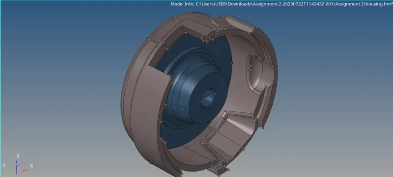
Fig 1: Isometric View Of Model (3D Tetra Mesh)
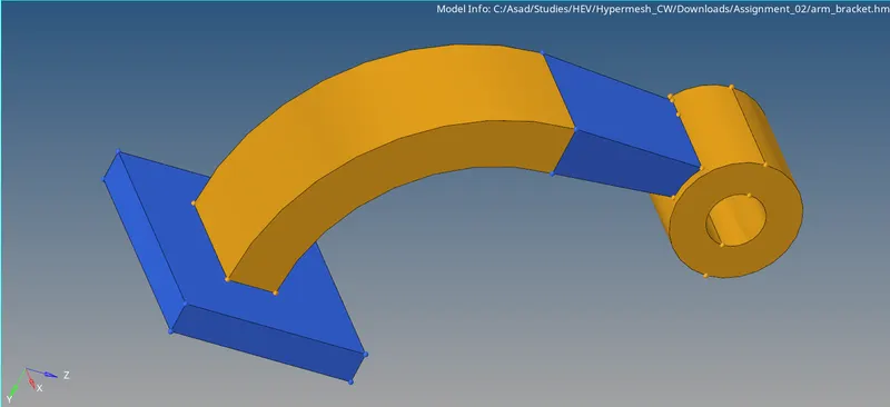
Fig 2: Isometric View Of Model (3D Hexa Mesh)
3. Procedure
3D Tetra Meshing
Step 1: 3D Tetra Meshing Hub
The model has 2 components. One is Hub and the other one is Cover. So here we use different 3D meshing techniques for each component. Initially add the quality criteria. Here we take the maximum element length as 7 units and the minimum element length as 2.
For the Cover, initially, we have to mesh the surface of the hub using tria elements by, Volume Tetra mesh.
- 3D >> Tetra Mesh >> Volume Mesh >> Select Displayed Surfaces >> Input Element Size >> 2D Type = Tria >> 3D Type = Tetra >> Element Order = First >> Mesh.
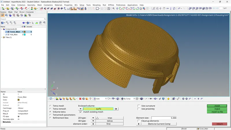
Fig 3: 3D Tetra Mesh of Cover Using Volume Tetra Mesh
Step 2: 3D Quality Checking and Element Correction of Cover
Check the quality of 3D elements. Here there are no failed elements. If there are any failed elements we can use distance to change the distance between the nodes and get rid of tet collapse.
- Tools >> Check Elements >> 3D >> Tet Collapse= 0.15
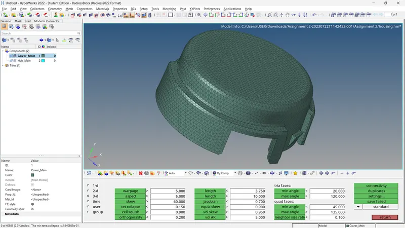
Fig 4: 3D Quality Checking of Cover
Step 3: 3D Tetra Meshing of Hub
For the hub, we have to initially extract the 2D mesh using tria elements. Edit the number of nodes to get a better mesh flow.
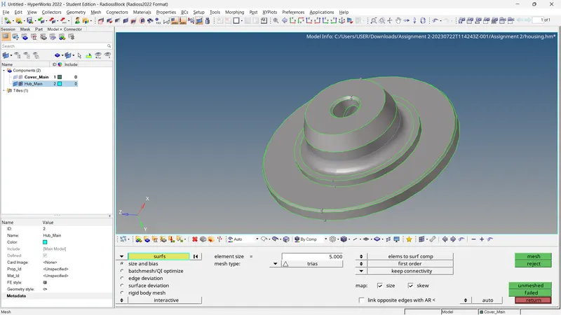
Fig 5: 2D Tetra Meshing of Hub
Check for the quality criteria. If any elements fail in minimum or maximum element length,
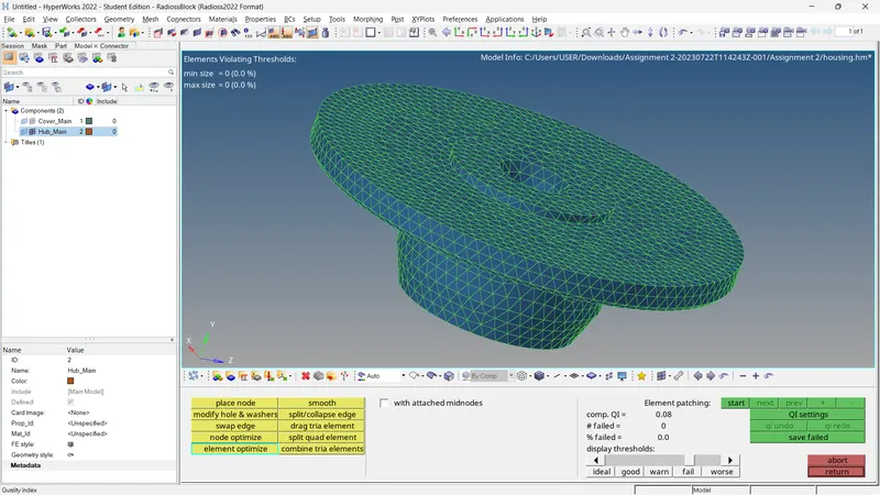
Fig 6: 2D Quality Checking of Hub
Step 4: Tetra Meshing and Quality Checks.
For generating 3D elements using the 2D elements,
- 3D >> Tetramesh >> Select all Tria Elements >> Mesh.
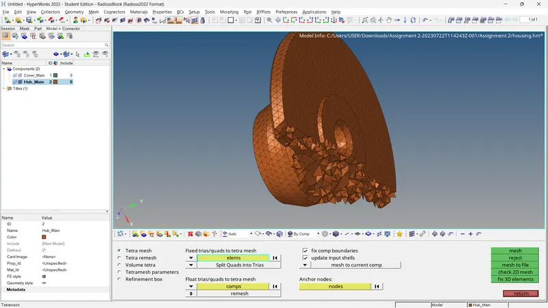
Fig 7: 3D Tetra Mesh of Hub
Delete or move all 2D shell elements (Config > Tria3) from the mesh. Check for tet collapse.
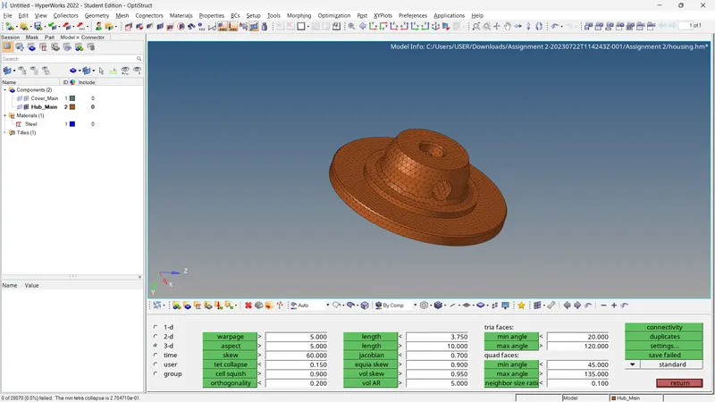
Fig 8: 3D Quality Checking of Hub
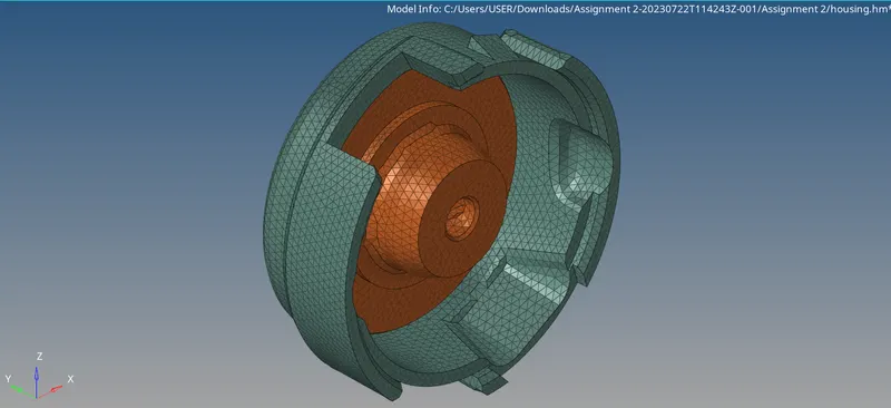
Fig 9: Final Resul (3D Tetra Mesh)
3D Hexa Meshing
Step 1: 3D Hexa Meshing of Base
The model contains 4 individual components. Each of them needs separate methods for meshing. Initially, we take the 'base' component and we use element offset for meshing. For that, the one surface of components is mesh with quad elements. Ensure there are no tria elements in the mesh. Then,
- 3D >> Element Offset >> Select Source Elements >> Number Of Layers = 5 >> Total Thickness = 25 Units >> Offset
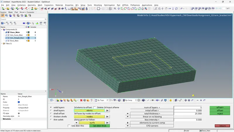
Fig 10: 3D Hexa Mesh of Base Using Element Offset
Step 2: 3D Hexa Meshing of Arm Curve
Here the Hexa meshing is done using the Spin option. We can spin the required quad mesh generated early to create hexa mesh for a certain angle and radius.
- 3D >> Spin >> Select 2D Elements >> Select N1, N2, N3 and B >> Spin Angle = 90 Degree >> On Spin = >> Spin
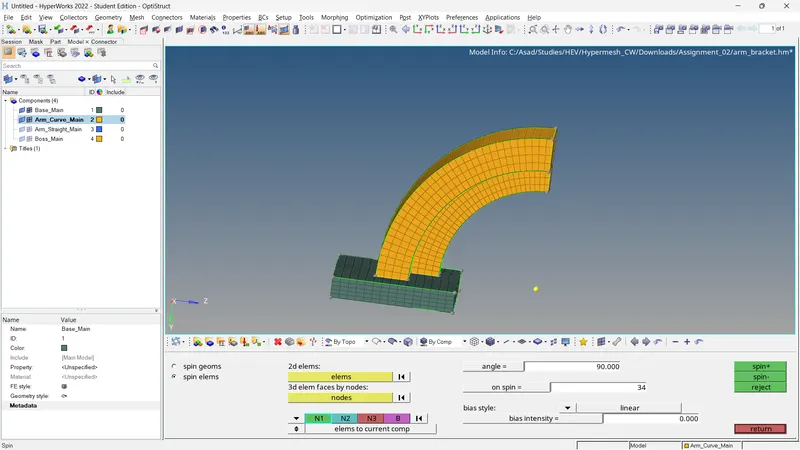
Fig 11: 3D Hexa Mesh of Arm Curve Using Spin
Step 3: 3D Hexa Meshing of Arm Straight
For this component, we can use the linear solid option. First, create 2D shell elements from the Arm_Curve Using the Face option. The Mesh Destination surface using 2D quad elements. Ensure the number of nodes on each source and destination surface is equal. Then Using
- 3D >> Linear Solid >> Select Souce Elements >> Select Destination Elements >> Select N1, N2 and N3 in Both Element Selection In Same Place >> Density = 11 >> Solids
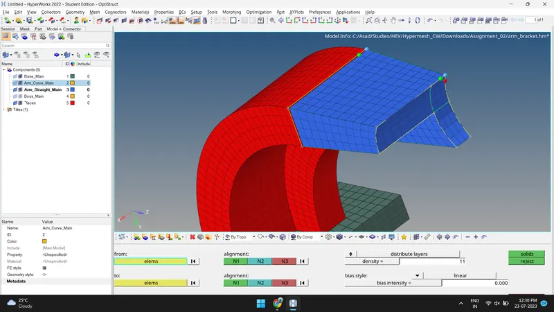
Fig 12: 3D Hexa Mesh of Arm Straight Using Linear Solid
Step 4: 3D Hexa Meshing of Boss
The surface of the component has meshed with 2D quad elements. Match the number of nodes with the Arm_Straight Component. Here we use the solid map. For that create necessary nodes using the project tool. Then
- 3D >> Solid Map >> Souce Geometry = None >> Select Destination Geometry >> Select Nodes In Along Geometry >> Select Elements to Drag >> Mesh.
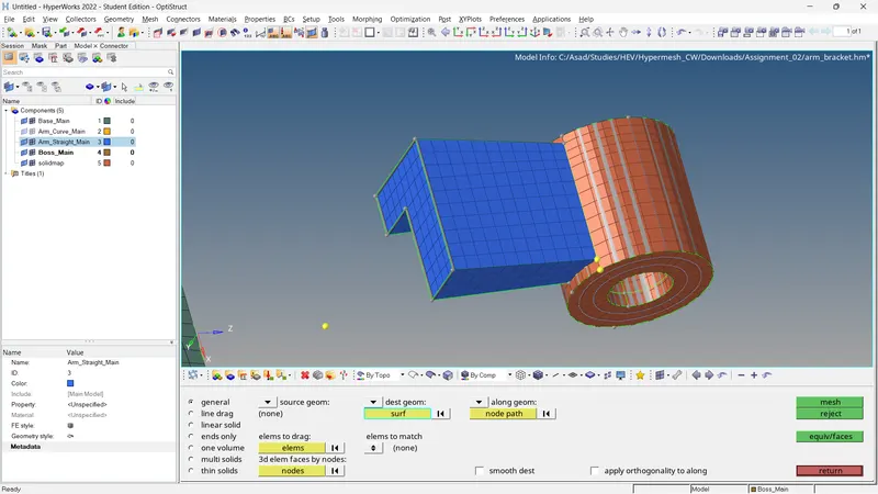
Fig 13: 3D Hexa Mesh of Boss Using Solid Map
Delete all quad elements by
- Delete >> Elements >> By Config >> Quad4 >> Delete
Check for free edges and equivalence.
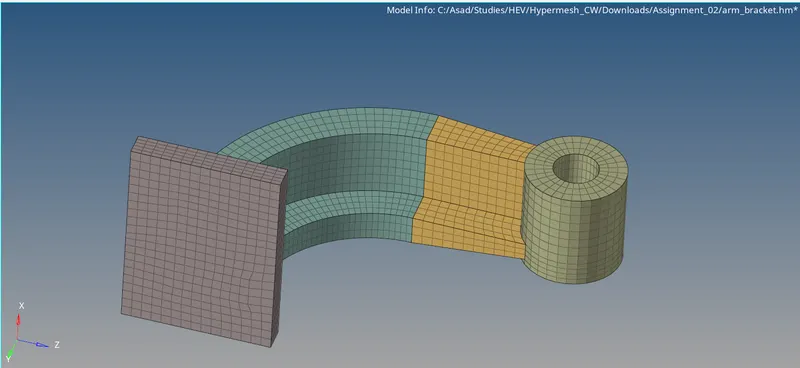
Fig 14: Final Resul (3D Hexa Mesh)
Engine File Editing
Initially, we have to import the engine file 'FIRST_RUN_0000.rad' to hyper mesh.
- File >> Import >> Solver Deck >> Browse File location >> Import.
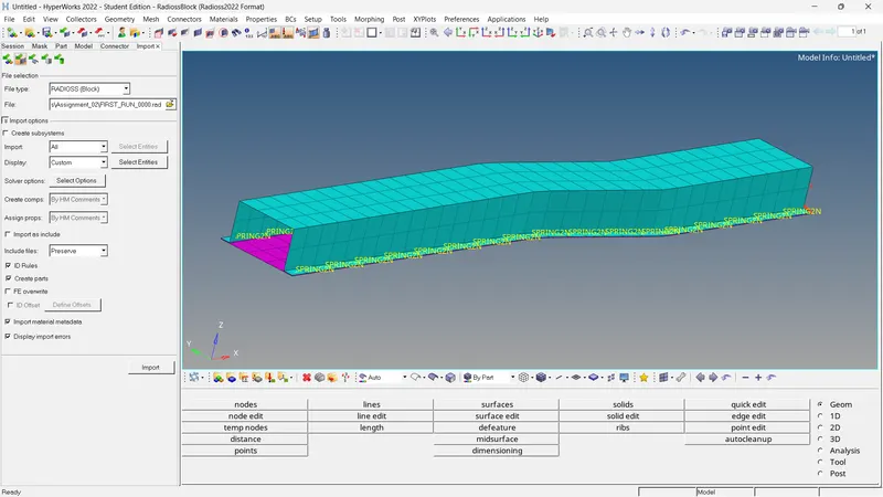
Fig 15: Importing Of Engine File
Open Solver Browser by
- View >> Browsers >> Hyper Mesh >> Solver
1) We know, Speed Of Sound, C = √ (E/ρ)
Where, E= Youngs Modulus Material
ρ= Density Of Material
To get those material properties, we can use the solver browser.
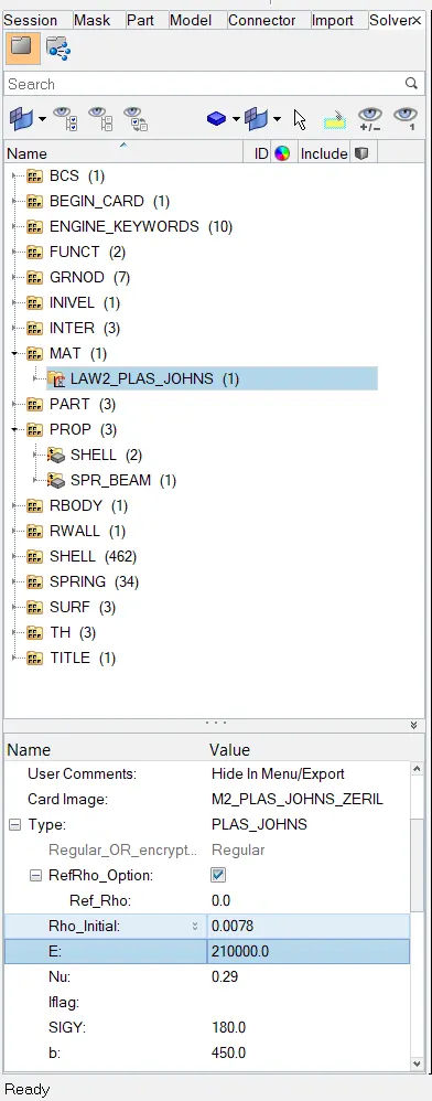
Fig 16: Material Properties
From this E = 210000.0 N/mm^2
ρ = 0.0078 g/mm^3
Speed of Sound Through Rail, C = √ (210000/0.0078)
= 5188.7452 m/sec
2) Time Taken for a shock wave through the rail, t = l/C
Where l = Length Of Rail = 1000mm =1 m
C = Speed Of Sound = 5188.7452 m/sec
So, t = 1/5188.7452
= 0.0001927 sec
= 0.1927 milliseconds
3) Time for sound to travel the length of rail= 0.1927 milliseconds
4) The time for sound to travel the length of the rail is 0.1927 milliseconds. It means the total runtime will be 0.1927 milliseconds. Input this value to the engine file through the solver browser.
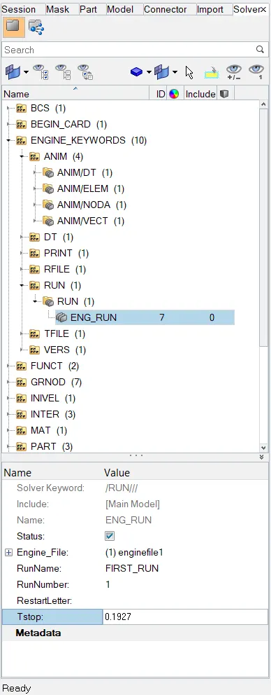
Fig 17: Editing Run Time
5) Frequency of animation output to a time that will give 20 animation steps = 0.1927/20
= 0.009635 MilliSeconds
Input this value to the engine file through the solver browser.
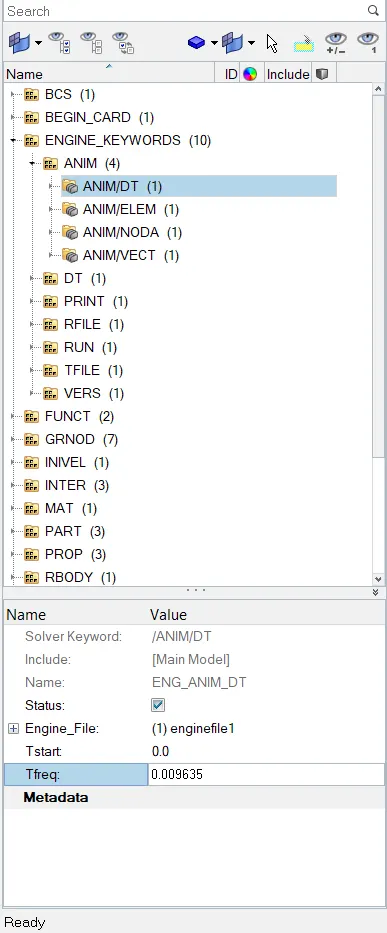
Fig 18: Editing Animation Frequency
6). Change /print -10.
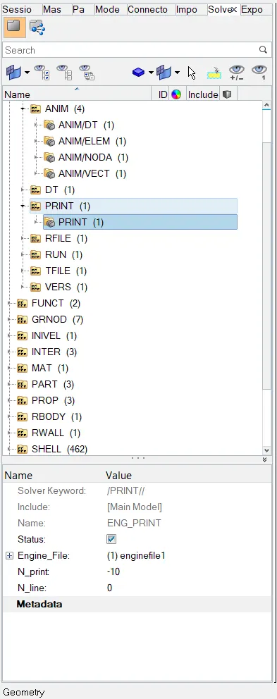
Fig 18: Editing Print Value
Export this file in .rad format. Open The 0001. rad file in Notepad.
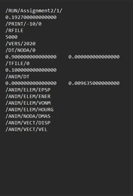
Fig 19: 0000.rad File
4. Conclusion
For 3D Tetra Meshing
- The components have meshed using appropriate methods.
- 3D Quality Checking is completed.
For 3D Hexa Meshing
- The components have meshed using appropriate methods.
- 3D Quality Checking is completed.
For Engine File Editing
- Speed of Sound Through Rail, C =5188.7452 m/sec
- Time Taken for a shock wave through the rail, t = 0.1927 milliseconds
- Time for sound to travel the length of rail= 0.1927 milliseconds'
- Frequency of animation output to a time that will give 20 animation steps = 0.009635 MilliSeconds
- The file is exported in the hyper mesh and the input calculated values through the solver browser.
- Export the file and open the .0001rad file.
5. Results
- For the given models, the appropriate 3D mesh is generated. The generated mesh satisfies the following 3D quality criteria.
- With the help of the engine file, the mentioned values are calculated and made changes using those calculations and exported the file to 0000.rad format.