Assignment 2-RADIOSS Engine File Editing & 3D Meshing Challenge
1. Check the material properties of the rail component and calculate the speed of sound in steel rail=_______
Material properties from FIRST_RUN_0000
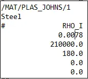
Density of Steel,ρ">ρρ = 0.007850 g/mm3
Young's Modulus, E = 210000 N/mm2
Elemental Time Step Equation, `Delta`tc=l/c
Where:-
Deltatc=time critical
l=characteristic length of the smallest element
c=Speed of sound in the material
c=`sqrt`E/`rho`
where E=Elastic limit of a material
`rho`= Density of a material
c=210`xx``10^3`/ 7.8`xx 10^-3`=5188.737 mm/ms`
`herefore speed of sound in steel rail = 5188.737 mm/ms
2. The length of the rail is about 1000 mm. calculate the time it takes for a shock wave to travel from one end of the rail to the other.
hear we have a length of 1000 mm
We have, δtc=lc=10005188.737=0.192725">δtc=lc=1000/5188.737=0.192725
tc=0.192725
3. Time for sound to travel the length of rail =`nbsp;0.192725 m`
4. Edit the engine file so that the stress wave can be monitored, moving from one end of the rail to the other during impact -this will require a termination time equal to the time it takes for the sound to travel the length of the rail(set on/RUN card)
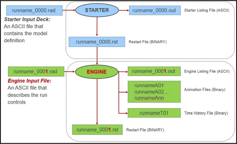
- In the radios solver, For every simulation, we will be having two files called
1) Starter File-file that contains the model definition
2) Engine File-file that describes the run control.
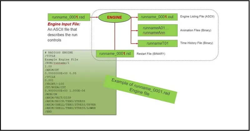
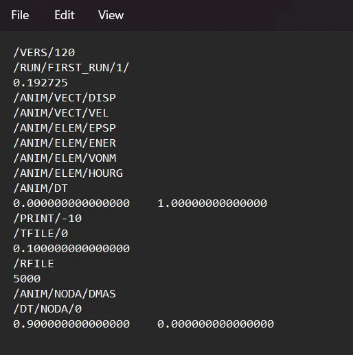
Engine file keyword-
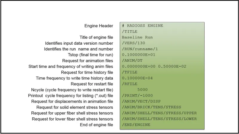
- After giving the value in WordPad
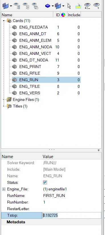
2) In the second method, we change the value in the hypermesh itself. There we go to the ENG_RUN card. There we change the Tstop value. There we have to give the value to be 0.1935 and after that, we have to run the file. So it will change the values in the 0001.rad file itself.
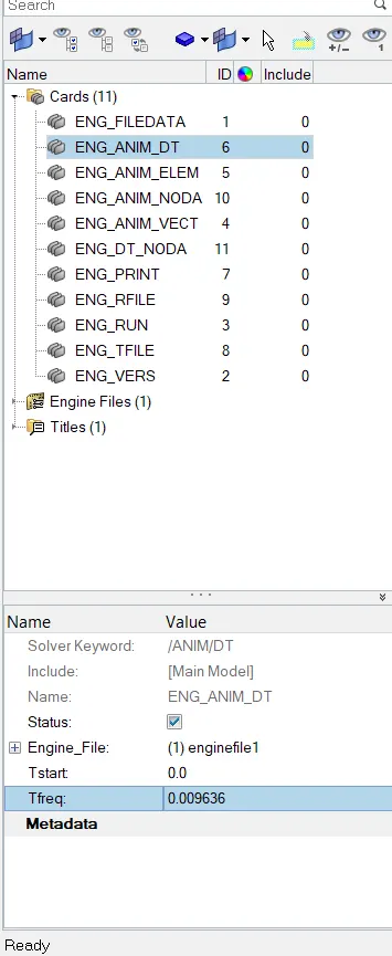
5. Set the frequency of animation output to a time that will give 20 animation steps(/ANIM/DT)
Frequency, F = Termination time/Animations Steps
= 0.192725/20 = 0.009636 ms
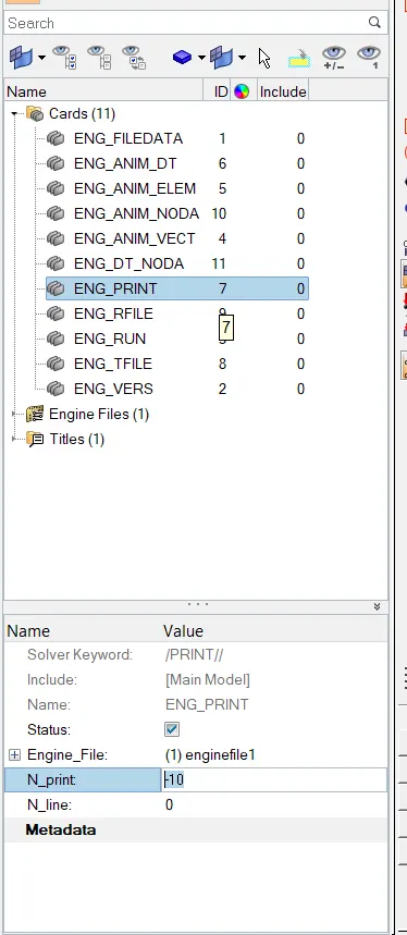
6. Change /print -10.
7. 3D Meshing Tetra Mesh
1) Import CAD model:-
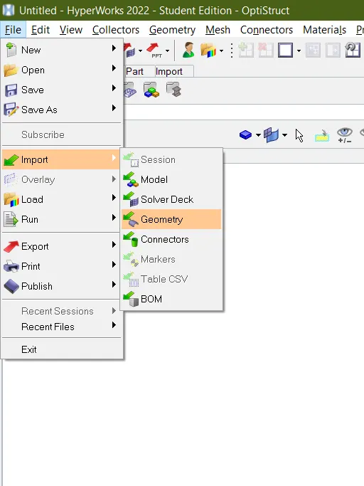
this cad model file in .Stp so that import this file by using option (File>Import>Geometry>select CAd model>import)
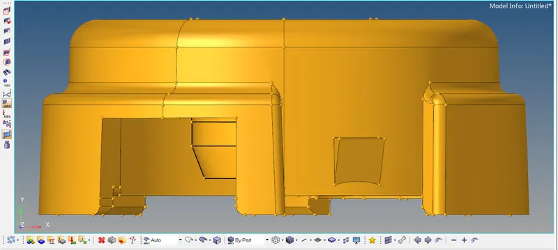
the cad model look like in below image-
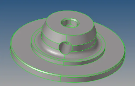
After import the model provided CAD model of consisting of Two components given below-
1) Hub.
2) Outer cover.
1) Hub:- 2D to 3D Convert.
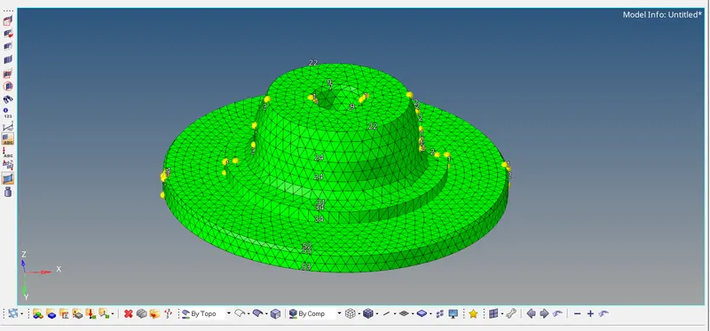
For this component do the 2D mesh as per the given condition.
(2D>Automesh>Surfs>Display>Elemitnt size_5>Mesh type_Trias>Mesh)

mention the target element size is 5 and select the mesh type as trias. select the surface and mesh the given component
Once 2d created than convert this 2d into 3d by using (3D>Tetra Mesh>2dElement>Display>mesh)


Since we have 0 tet collapse failures, we can move on to the next component and repeat the process.
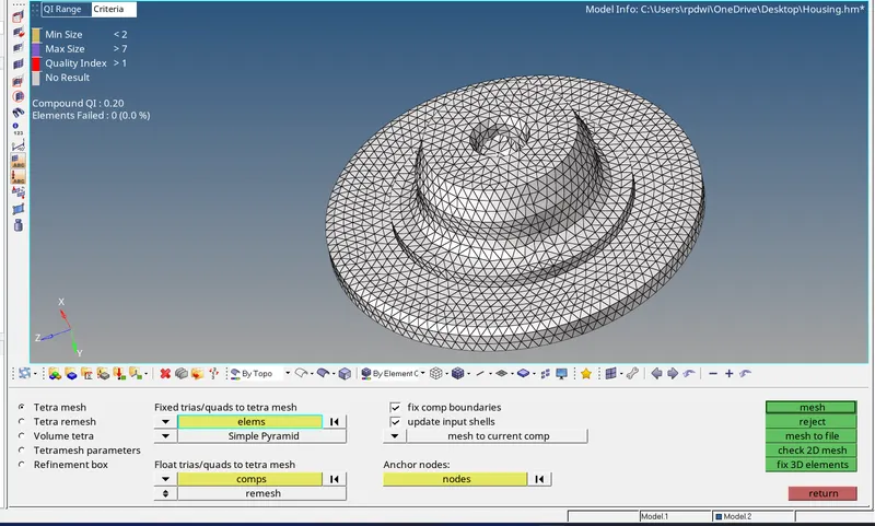
Final image with 3D Element Showing by using (F5/Mask>select element>Mask)
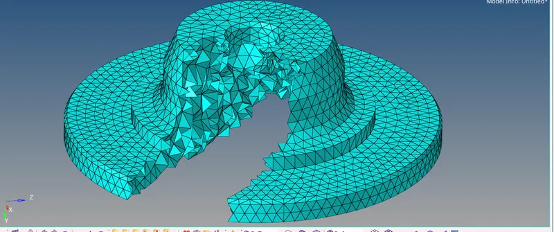
2) Outer cover-
-
In the second model, we will perform Volume tetra mesh on the model.
by using this tool (3D>Volume tetra>Select Solid >Enter element size_3>2D_Trias>3D_Tetras>Tik_Use curvature and Use proximity>mesh)
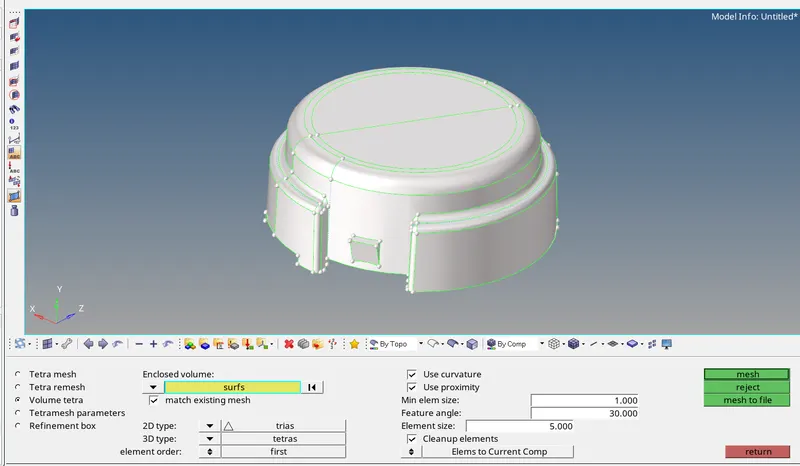
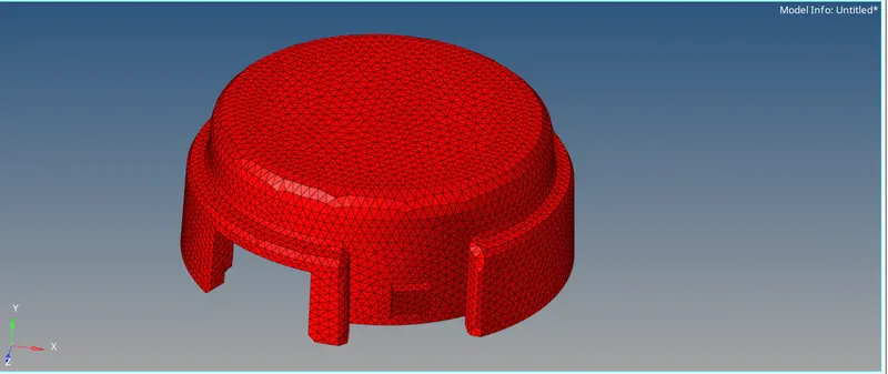
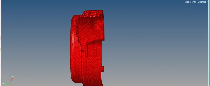
All the Operation NO tet collapse Present in this component Final image as below-

2. Arm Bracket Model [Hexa Mesh]
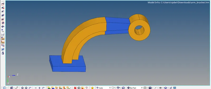
- Here the arm bracket has been imported into GUI which is shown in the below image.
- Now there are four components in the model called Base, Arm Curve, Arms Straight, and Bose.
- Isolate the Base Component only and mesh the component with the shell elements and then mesh with the hexahedral elements.
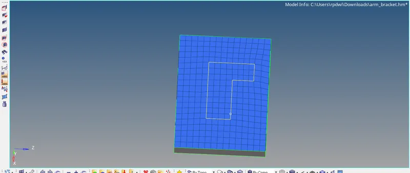
- Now first mesh the upper surface with 2D shell elements and then create hexa elements.
- Go to the (Automesh Panel >Surfaces >Element Type:Quad >Enable Align,Size,Skew>Mesh)
- 2D shell elements have been created as shown in the below image in order to create hexa elements.
- Now Go to 3D panel >> Element Offset.
- To create hexa elements.


- Select all the side surfaces of base component to follow along the geometry.
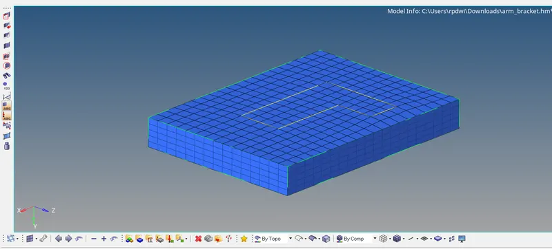
- Give the number of layers as 5, to get 5 row of elements over the base component.
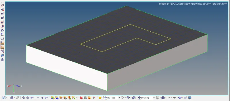
Selecting the Elements and Surface to Offset to Create Hexa Elements.
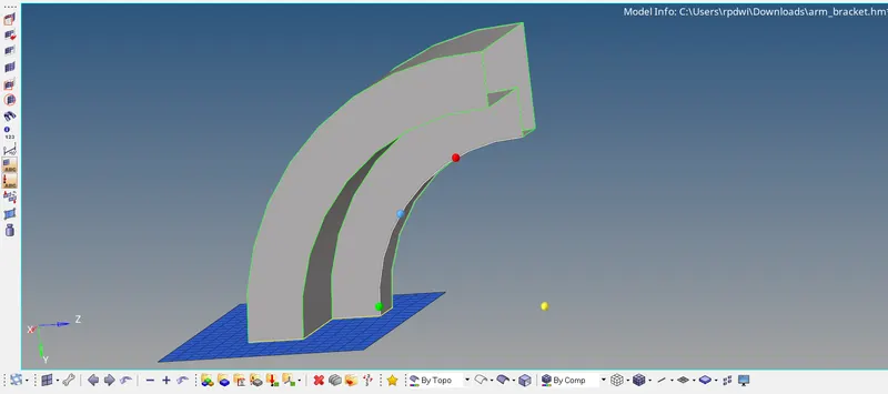
- To spin the elements, First, we have to create a central node called the base node to create hexa elements.
- To Create, Go to (F4>Three Node>Select direction>circle centre)
- Node has been created.
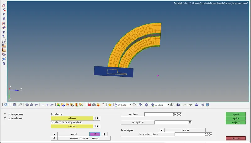
- To get the shell mesh of section 2, Tool → faces → elements are used. It appears exactly like the 3d Hexa mesh of section 2, it is hollow from the inside.
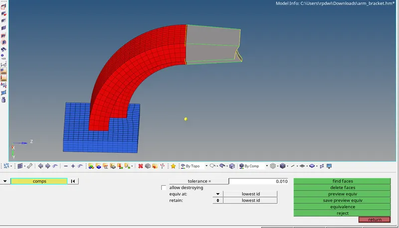
Now, to mesh section 3, the rows and columns of shell elements available on one side of it, the other side has to mesh with the same number of rows and columns using shell elements
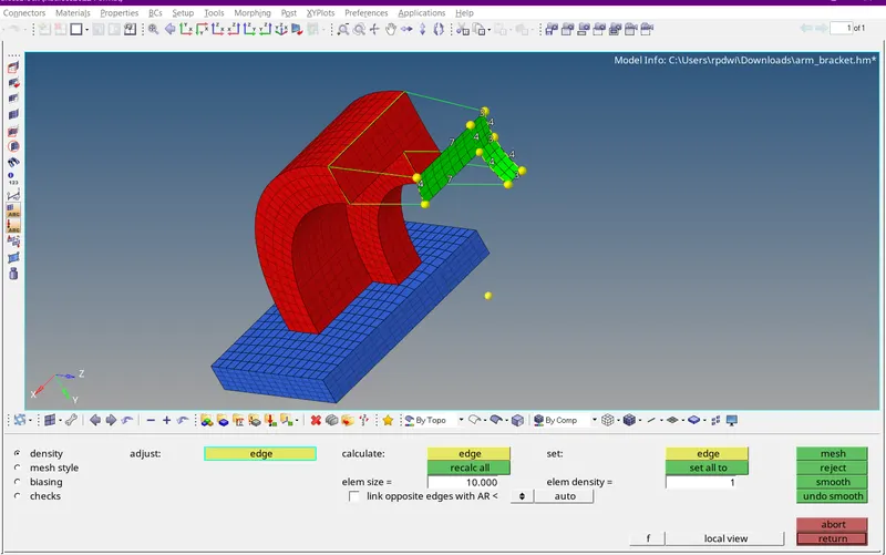
- Here select the elements in the source geometry and select the elements in the destination geometry.
- Now align the nodes in the both source and destination geometry.
- Give an appropriate density value and hit on solids to create hexa elements
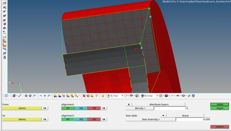
Selecting the Source and Destination Geometry, Aligning Nodes in Source and Destination Geometry.
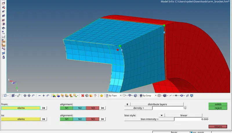
- Next component is bose,Enable the bose component in the model browser.
- For this component,Solid Map tool is used to generate hexa elements.
-
- Now project the node to the surface to select the node path in along geometry.
- To project,Go to Tool >> Project >> To Surface >> Nodes >> Duplicate >> Select Surface >> Surface Normal >> Project.
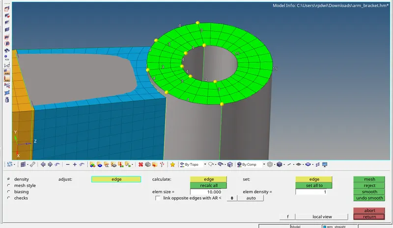
Final CAD Model Image with Cut section.
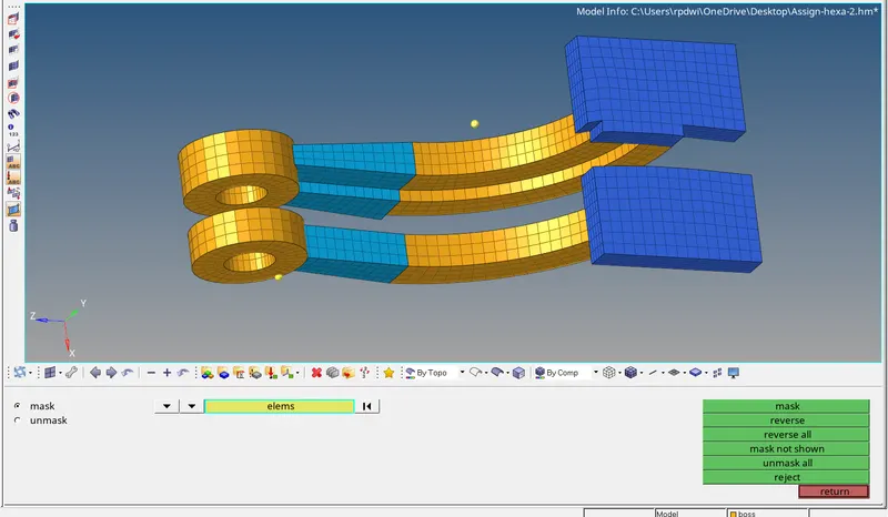
Result -
- Hence the Engine File has been edited successfully with the values calculated.
- Hence the 3D Meshing has been generated for Housing Model with Tetra Elements.
- Hence the 3D Meshing has been generated for the Arm Bracket Model with Hexa Elements.
Learning Outcome-
- The types of files for the Radioss Block
- How to edit the Engine File.
- How to mesh the component with hexa elements.